Tevatron Experimental Issues at High Luminosities
Abstract:
In this paper we describe the detector components, triggers and analysis techniques for flavor physics at the Tevatron experiments CDF and DØ. As Tevatron performs very well and runs at higher luminosities regularly we also touch issues related to it and efforts to improve detectors and triggers for such running.
1 Introduction
The Tevatron collider with TeV provides an excellent opportunity for the heavy flavor physics, which is complementary to the colliders operating at resonance. Main advantages are the large hadron cross section of b for hadrons with and [1], which is three orders of magnitude higher than at colliders and the large available energy for the production of all sorts of hadrons. The main challenges consist of a large inelastic cross section which is about three orders of magnitude higher than hadron cross section and a fragmentation at high energies, which produces a large amount of particles in the detector. In this paper we discuss how we deal with the challenges, starting from description of CDF and DØ detectors and trigger strategies. For several important measurements, flavor tagging is an important tool and we will describe its main concept. Finally we discuss issues of running at high luminosity and ways how we deal with them.
2 Detectors
Both CDF and DØ are multipurpose detectors exhibiting cylindrical and forward/backward symmetry. Details of the detectors are described in Ref. [2] for CDF and in Ref. [3] for DØ. They have same basic structure starting with tracking detectors located in a magnetic field in center, electromagnetic and hadronic calorimeters outside the solenoid and a muon system behind the calorimeters. In the following we use a coordinate system in which proton beam direction defines -axis. Angles and are the polar and azimuthal angles defined with respect to the -axis. The pseudorapidity is defined as and the transverse momentum is .
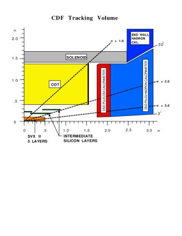
The CDF tracking consists of silicon tracker close to the interaction point, which is complemented by a large volume open cell drift chamber (COT), both immersed in the 1.4 T magnetic field. Schematic view of the tracking system is shown in Fig. 1. The silicon detector itself consists of three subcomponents. First one is a single layer of one sided silicon strip detector (Layer00) mounted directly on beam pipe at a distance of 1.5 cm from the beamline [4]. The main part consists of 5 layers of double sided strip detector (SVX II) with radial extent between 2.5 and 10.6 cm from the beamline [5]. The last part called ISL provides single double sided layer for at radius of 22 cm and two layers at 20 and 28 cm for [6]. The active volume of the COT extents from 43.4 to 132.3 cm from the beamline and provides a full coverage for tracks with [7]. Cells are grouped into 8 superlayers in radial direction, each consisting of 12 cells. Four of the superlayers are axial and four have small stereo angle to provide information in the view. The two types of superlayers alternate with outermost one being axial superlayer. The integrated tracker provides a transverse momentum resolution of .
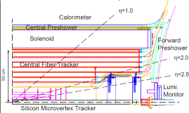
The DØ tracking consists of a silicon microstrip detector complemented by a fiber tracker at larger distances from the beamline, both immersed in the 2.0 T magnetic field. Layout of the tracking system is shown if Fig. 1. The silicon detector provides four layers of double sided sensors in the central region and two double sided with two single sided sensors in the forward/backward regions. The innermost layer is located at 2.7 cm and outermost at 10.5 cm. In the forward and backward region additional disks of silicon sensors are installed perpendicularly to the beam direction to further enhance tracking at large . In 2006 the silicon detector was extended by an additional layer mounted close to the beampipe in order to improve the impact parameter resolution of tracks. The fiber tracker is based on scintillating fibers. The 16 layers are located from radius of 20 cm up to radius of 52 cm. The full tracking detector provides coverage up to .
Both experiments contain electromagnetic and hadronic calorimeters covering large part of the phase space. They are optimized for high physics and thus only of limited use in heavy flavor physics. The electromagnetic calorimeters are used for electron identification with main use in flavor tagging. Photon detection is possible to some extent, but none of the experiments exploited it up to now.
Muon detection is one of the key components for flavor physics at Tevatron. CDF detects muons in a set of drift chambers and scintillators. The central muon detector [8] is located outside the hadron calorimeter and covers . In the same central region detectors behind an additional absorber provide improved identification in exchange of increased threshold. For run 2 the muon coverage was extended up to . The threshold of the muon systems is between to depending on the region. The muon system of DØ consists of drift tubes complemented by scintillator counters. The main difference to the CDF system is in coverage, where DØ system covers up to . Thanks to an additional toroid with magnetic field of 1.8 T, the DØ muon system provides standalone momentum measurement for muons. In addition, there is a more material in front of the muon chambers, which results in a lower background compared to CDF.
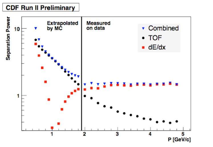
While DØ does not have dedicated particle identification for hadrons, CDF experiment utilizes two detectors to separate kaons from pions. The first information is provided by the COT, where thanks to its large volume and number of measurements along the track, measurement is used for separation. This is complemented by the time-of-flight detector (TOF) [9], which is located between COT and solenoid. It consists of 216 Bicron scintillator bars and covers . With time resolution on the single hit of 110 ps it provides better than separation between kaons and pions for . Figure 3 shows the separation power as a function of momentum for the combined system. The separation power is at least over the whole interesting momentum region. It is worth to note that and TOF measurements complement each other. While separation is not sufficient for track-by-track identification, it provides reasonable statistical separation.
To summarize detectors, both provide reasonable performance for flavor physics at hadron colliders and both experiments contributed with important measurements. DØ detector has its strengths in the muon detection with considerably larger coverage in . Additional advantage not discussed here is in a regular swap of the polarity of magnetic field in solenoid and toroid magnets. On contrary, CDF detector thanks to the larger radial extent of the tracker has excellent momentum resolution, which reflects itself to a very good mass resolution. The particle identification provides additional advantage over DØ detector.
3 Trigger strategies for -physics
While the hadron cross section is rather large, the inelastic cross section is three orders of magnitude larger. With a collision rate of 1.7 MHz and a size of an event of order 100 kB the data flow is of order 200 GB per second. Such data rate is beyond current storage system capabilities. Therefore flavor physics at hadron colliders critically depends on the ability of the trigger to select heavy flavor events with good efficiency and huge background rejection. The basic three level architecture of the trigger system is the same in both experiments. The level 1 is implemented purely in hardware and the main information used for its decision comes from the muon system and the tracking in the fiber tracker at DØ and the COT at CDF. The level 2 is a mixture of hardware and software implementation, which allows more flexibility. Here both experiments have access to the whole detector including silicon tracker, but only CDF exploits silicon information for triggering. Finally, level 3 is implemented purely in software running on dedicated computing farms. It runs a speed optimized version of the offline reconstruction software. In most of the cases, the level 3 reconfirms decisions of the previous levels with higher precision. The DØ level 1 trigger has latency of 4.2 s and reduces the accept rate from 1.7 MHz to about 2.5 kHZ. Level 2 has about 100 s for its decision and reduces the rate to approximately 1 kHz while the level 3 reduces the rate to a final value of 200 Hz. At CDF the level 1 has about 5.5 s for its decision and reduces the rate down to about 20-30 kHz. The level 2 has an average latency of 20 s with an output rate of about 700 Hz. Finally level 3 provides an output rate of about 120 Hz.
The trigger strategy at DØ is based purely on muon detection. There are two classes of triggers, one requiring two muons of opposite charge and one with single muon requirement. First strategy is used for studies of decays with in the final state like the measurement [10] or searches for rare decays with prime example [11]. The second class of triggers is used with semileptonic decays (e.g. study of with one decaying semileptonically) or fully hadronic decays used in the mixing measurement [12]. The triggering of fully hadronic decays is based on the assumption that the muon originates from a decay of the second hadron in the event. The triggered sample has lot of background, but every single event can be flavor tagged using the trigger muon.
At CDF thanks to the use of information from silicon detector the trigger strategy is different from DØ. The main information at level 1 comes from the muon detection and use of the extremely fast tracker (XFT) [13] which finds tracks in the axial layers of the drift chamber. The threshold of the XFT is 2 . At level 2 the silicon vertex trigger (SVT) [14] play a crucial role in adding hits in silicon to the tracks found by XFT and in measuring impact parameters of tracks with a typical resolution of order 50 m including the beam size. This allows for the selection of tracks coming from displaced vertices and thus triggering also on decays which do not provide lepton in final state. Altogether, three classes of triggers are used. First class requiring dimuon pair of opposite charge is similar to DØ and is used for similar physics like measurement of [15] or search for [16]. The second class requires one lepton (muon or electron) with and an additional track with large impact parameter. This class is designed for semileptonic decays. The third class requires two tracks with a large impact parameter (at least 100 m) which are consistent with common vertex with a sizeable displacement from the beamline and CDF is first experiment to implement this kind of trigger. It is this last trigger strategy that allows to select decays like used for the mixing observation [17] or which provides largest samples in the world for mixing and CP violation measurements [18].
4 Flavor tagging
One of the important tools for the physics goals of the Tevatron run 2 is a flavor tagging of the hadrons. The task of the flavor tagging is to find out whether a hadron was produced as or . Without such tool the mixing [17, 12] would be impossible. It is also crucial tool for the time dependent CP violation measurements, which experiments try to perform these days.
At Tevatron, quarks are produced in pairs of opposite flavor. After hadronization, they end up in different hadrons. One which is used in a given study is usually called same side hadron. The other hadron is often referred to as the opposite side . The flavor tagging is then split into two categories, the opposite side taggers (OST) and the same side tagger (SST). The OST exploits decay of the opposite side , while SST examines fragmentation partners of the same side . The performance of the flavor tagging is characterized by efficiency which a gives fraction of events in which a decision is made and dilution which is related to the probability that event is correctly tagged by . The quantity than defines an effective statistic corresponding to perfectly tagged events. Some details of the algorithms are described in Ref. [19].
The OST tagging is based on the leptons arising from semileptonic decays, jet charge or secondary vertex charge and charge of the kaon from the decay chain . We use both muons and electrons for the lepton tagging. At CDF, a likelihood based selection is used while DØ uses rectangular cuts for lepton identification. In CDF jet charge tagger is employed, while DØ uses secondary vertex charge. The jet charge tagging of CDF starts with track based jets in which it tries to search for a secondary vertex. For each jet, charge is calculated as , where sums run over all tracks associated with jet. CDF, thanks to its capability of separation, is able to exploit also opposite side kaon tagging. In case of both experiments, different taggers are combined using multivariate techniques to a single opposite side decision. Altogether, as DØ has the better muon coverage and cleaner muon detection, they achieve better performance than CDF.
The SST is based on the fact that to produce one needs an quark from popup. Afterwards quark has to end up in a hadron, which is often . If it is a charged kaon, its charge defines, whether it contains quark or anti-quark and thus also defines production flavor of the . Both experiments exploits this idea for flavor tagging. While DØ is selecting a tagging track (fragmentation partner) based on the kinematical relation of tracks to a candidate, CDF combines kinematical information with particle identification information for this task. Thanks to particle identification, CDF has better performance in this tagger.
Both experiments have tagging power of . The opposite side taggers are usually calibrated by measuring well known oscillations as it exploits information which is independent of the same side hadron. The SST is developed and studied on simulated events, but mixing measurements indicate that understanding of the taggers is reasonable. Unfortunately the mixing measurement itself did not provide sufficient statistics for a high precision calibration up to now.
5 High luminosity running and upgrades
Tevatron went through many optimizations and improvements in operation procedures over the past two years [20]. Those improvements result in a better stability of the accelerator as well as in higher initial luminosities for stores. In Fig. 3 we show development of the initial luminosities as a function of time. It can be seen that since about mid 2008 they are consistently above cm-2s-1.
As the luminosity increases, demands on the detectors and trigger systems increase as well. This is due to the fact that at luminosities above cm-2s-1 we get on average about 10 inelastic collisions. It results in more particles inside the detector and thus more information which trigger system needs to process and higher chance of the coincidence of unrelated trigger objects to pass the trigger requirements. Additionally also radiation seen by the detectors increases, which is specially important for the sensitive silicon detectors, which are mounted closest to beamlime. In Fig. 4 we show the signal to noise ratio for CDF silicon detectors and the depletion voltage of the DØ detector as a function of luminosity.
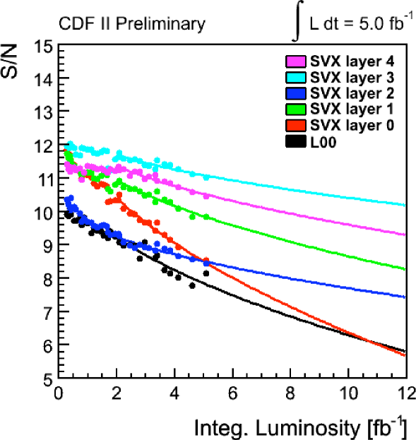
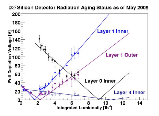
Currently we collected about 6 of data and silicon detectors of both experiments are fully operational. For CDF we expect no significant degradation in offline performance for above 3 and in trigger performance for above 6. As can be seen from Fig. 4 the silicon detector is expected to perform without significant degradation up to about 12 . At DØ, detector projection tell that the silicon detector can be operated without large issues up to 12 . Only significant issue might be with the Layer 1, which is mitigated by installation of the Layer 0 in 2006. No significant performance degradation is therefore expected even if Layer 1 stops to operate. From the offline tracking point of view additional interactions per bunch crossing do not cause any significant issues. This is given by the length of the bunches, which is large enough to provide primary vertices with large enough separation in order to distinguish them by tracking.
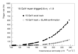
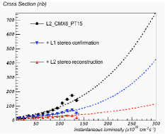
The main issue related to the high luminosity running comes with trigger. Trigger rates often increase more than linearly as one would expect from a pure physics of interest. Continuous effort is made by experiments to optimize their trigger strategies to keep up with the performance of the accelerator. As both CDF and DØ are multipurpose experiments, it sometimes results in optimization of not only heavy flavor triggers, but also high triggers. At CDF we perform additional upgrades of the trigger systems to cope with higher rates. First of the upgrades, which is in successful operation was the upgrade of XFT system [21]. Original system was capable to perform tracking only in axial layers of the COT. The upgrade added possibility of tracking also in stereo layers, which improves the background rejection significantly. Example of the effect of the upgrade can be seen on Fig. 5.
Second upgrade currently ongoing concerns the SVT subsystem. Already in 2006 we exchanged Associative Memory boards to ones with more memory which are capable to store more patterns. This upgrade allowed to improve resolution and decrease the background rate. Currently we are in a commissioning phase of a second upgrade which exchanges track fitting boards by GigaFitter board, which is a new generation of online track fitting processor [22]. It allows further increase in precision as well as removes prolongations in the processing time for events with more tracks.
6 Conclusions
To conclude, both Tevatron experiments are able to provide important results in the heavy flavor sector, including highly nontrivial measurements of the time dependent CP violation and neutral meson mixing. Both collaborations are still in the position to keep up with improvements on the accelerator side and thanks to the effort of accelerator and detector experts we are collecting new data with an unprecedent rate. With approved running in the fiscal year 2010 we expect to collect about 8 by each of the experiments. In likely case of running through 2011 we expect to have about 10 of good data available for analysis at each of the experiments. Altogether, there is strong will inside the community to provide over next few years competitor in the physics to the LHC experiments.
References
- [1] T. Aaltonen et al. [CDF Collaboration], Phys. Rev. D 79, 092003 (2009).
- [2] D. E. Acosta et al. [CDF Collaboration], Phys. Rev. D 71, 032001 (2005).
- [3] V. M. Abazov et al. [D0 Collaboration], Nucl. Instrum. Meth. A 565, 463 (2006).
- [4] C. S. Hill [On behalf of the CDF Collaboration], Nucl. Instrum. Meth. A 530, 1 (2004).
- [5] A. Sill [CDF Collaboration], Nucl. Instrum. Meth. A 447, 1 (2000).
- [6] A. A. Affolder et al. [CDF Collaboration], Nucl. Instrum. Meth. A 453, 84 (2000).
- [7] A. A. Affolder et al. [CDF Collaboration], Nucl. Instrum. Meth. A 526, 249 (2004).
- [8] G. Ascoli et al., Nucl. Instrum. Meth. A 268, 33 (1988).
- [9] D. Acosta et al. [CDF-II Collaboration], Nucl. Instrum. Meth. A 518, 605 (2004).
- [10] V. M. Abazov et al. [D0 Collaboration], Phys. Rev. Lett. 101, 241801 (2008).
- [11] V. M. Abazov et al. [D0 Collaboration], Phys. Rev. D 76, 092001 (2007).
- [12] V. M. Abazov et al. [D0 Collaboration], Conference Note 5618-CONF (2008).
- [13] E. J. Thomson et al., IEEE Trans. Nucl. Sci. 49, 1063 (2002).
- [14] B. Ashmanskas et al. [CDF-II Collaboration], Nucl. Instrum. Meth. A 518, 532 (2004).
- [15] T. Aaltonen et al. [CDF Collaboration], Phys. Rev. Lett. 100, 161802 (2008); CDF Public Note 9458.
- [16] T. Aaltonen et al. [CDF Collaboration], Phys. Rev. Lett. 100, 101802 (2008).
- [17] A. Abulencia et al. [CDF Collaboration], Phys. Rev. Lett. 97, 242003 (2006).
- [18] T. Aaltonen et al. [CDF Collaboration], Phys. Rev. Lett. 100, 121802 (2008).
- [19] T. Moulik, Nucl. Phys. Proc. Suppl. 170, 303 (2007).
- [20] M. E. Convery, arXiv:0910.1572 [physics.acc-ph].
- [21] A. Abulencia et al., Nucl. Instrum. Meth. A 581, 482 (2007).
- [22] S. Amerio et al. Nuclear Science Symposium Conference Record, 2007. NSS ’07. IEEE 3, 2115 (2007)