Self-Reference Ultra-Wideband Systems
Abstract
Towards employing low complexity transceivers for signal reception in Ultra-Wideband (UWB) systems, Transmitted Reference (TR) and Differential TR (DTR) schemes have attracted researchers’ attention. In this letter, we introduce an alternative, less complex scheme, called Self Reference (SR) UWB transceiver, which uses a modified replica of the received signal itself as reference pulse, resulting in double data rates compared to TR schemes. Moreover, SR eliminates the need for delay lines at the receiver side, which constitute a major drawback of the conventional TR and DTR schemes, while it also requires no channel estimations, resulting in lower complexity implementations and power savings. The performance of the SR scheme is investigated in high-frequency (HF) channels, showing that it offers a better or comparable performance to that of DTR, depending on the channel conditions.
Index Terms:
Differential Transmitted Reference UWB, Self Reference UWB, Transmitted Reference UWB.I Introduction
The optimum diversity combining scheme, in terms of performance, is the all-Rake (ARake) receiver which resolves all multipath components (MPCs) that are often more than 100 in typical Ultra-Wideband (UWB) scenarios [1]-[2]. In order to eliminate the need for the channel estimations, Hoctor and Tomlinson proposed a simple non-coherent Transmitted Reference (TR) scheme, which was able to capture the energy of the multipath components [3]. An unmodulated known reference pulse is transmitted prior to each data-modulated pulse within the coherence time of the channel in order for the two pulses to experience the same channel condition. An autocorrelation receiver is applied and the received reference signal is used as a template to demodulate the data symbol. Hence, each data bit requires the transmission of two pulses, that is the reference and the signal one, leading in a 50% rate loss. Moreover, TR systems experience a 3dB performance loss, because of the usage of a noisy template [4]-[6]. Another drawback is the requirement of a delay line, which increases the implementation complexity, adds extra power consumption and interrupts the synchronization at the reception. Synchronization in the sub-nanosecond range is the key parameter in the signal correlation, energy capture and data demodulation of IR signals for UWB systems [7].
An alternative Differential TR (DTR) scheme was presented in [8], offering double data rates and reduced inter-symbol interference (ISI). In DTR the data are differentially modulated using the previously sent data pulse, and hence the transmission of an extra reference pulse is not required. However, DTR still requires the implementation of the delay line. Moreover, due to the differential functionality, erroneous detection of a symbol may affect the correct tracing of the next one, resulting in performance degradation.
In this letter, we introduce a novel and simple scheme for UWB applications with binary antipodal modulation, called Self Reference UWB (SR), which uses as a reference signal the absolute value of the received signal multiplied by the positive Gaussian monocycle waveform. Compared to the conventional TR schemes which transmit two pulses for one data symbol, SR constructs the reference pulse from the received data symbol, resulting in double data rates (like DTR), lower complexity and saving of computational resources without adding further power consumption. Moreover, depending on the channel conditions the SR scheme offers comparable or better performance compared to DTR because of the elimination of the error propagation of DTR when a data symbol is erroneously decoded, while the absence of the delay line (implemented both in TR and DTR schemes) reduces the complexity of the system, the power consumption and the synchronization between the transmitter and the receiver. The performance of the SR scheme is investigated in high-frequency (HF) channels, showing that it offers a better or comparable performance to that of DTR.
II System Model and Mode of Operation
II-A Channel Model
The HF channel model (proposed by the IEEE 802.15.3a standardization group) is widely used in UWB research works and it is used for the evaluation of the performance of the proposed SR scheme. The HF UWB channel model is based on the Saleh-Valenzuela channel model [9] and is intended to represent the channel characteristics in the frequency range from 3.1 to 10.6 GHz [10]. According to this model, the received signal arrive in clusters each containing rays. The channel impulse response of the -th realization is defined as
| (1) |
where is the tap weight associated with the -th ray of the -th cluster, is the log-normal shadowing and are the cluster and ray arrival times, respectively.

II-B Conventional TR scheme
In a binary TR UWB communication system the transmitted signal is given by [8]
| (2) | |||
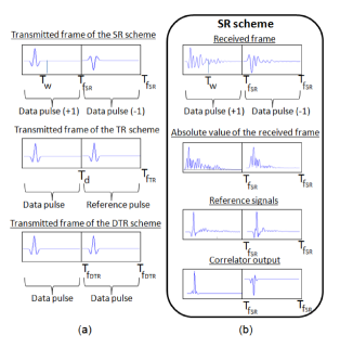
where are the equiprobable data bits, is the transmitted monocycle waveform that is non-zero for is the duration of the pulse and is the frame duration, which is assumed to be shorter than the multipath delay spread resulting in inter-pulse interference. The index i.e., the integer part of is the index of the data bit modulating the data waveform in the frame, while is the number of the transmitted frames, required for achieving an adequate bit energy at the receiver. The first sum of (2), (), denotes the transmitted information bits and the second sum, (), is the reference pulse transmitted seconds later (see Fig. 1).
The transmitted signal passes through the HF multipath channel and the received signal of the TR system can be written as
where denotes the received information bits, the received reference signal and represents the additive noise, which is a zero-mean complex Gaussian random process with two-sided power spectral density . At the receiver is delayed by seconds, using delay line, and then correlated with the first part, i.e., , so that a decision on the transmitted bits can be made.
II-C SR scheme
The mode of operation of the SR transceiver is depicted in Fig. 2. Analytically, the transmitted signal of the SR is given by
| (3) |
where is the frame duration of the SR, which is assumed to be shorter than resulting in interference between data pulses. The transmitted signal passes through the HF multipath channel and is corrupted by the AWGN. The received signal is given by
The basic idea behind the SR scheme is that for the case of binary antipodal modulation only, we can ”mimic” the positive reference pulse that is used in TR schemes, by using a modified version of the received data signal itself, e.g. the absolute value . Considering two different cases of the HF channel model111We note that the values of Table I, are the average correlation values, over HF channel realizations. and by simply using 222The absolute value of a signal can be obtained with a precision absolute value circuit [11]. as a reference for symbol detection, the correlation between and is not higher than for the high SNR regime (see Table I). This absolute self reference scheme (ASR) is problematic due to the cutoff of the negative values of the received signal.
| Data signal | Ref. signal | Correlation (CM1-CM2) | ||
|---|---|---|---|---|
| TR | 1 | 1 | ||
| ASR | 0.3829 | 0.3987 | ||
| SR | 0.6745 | 0.7055 | ||
A more precise ”mimic” of the actual reference signal can be obtained by multiplying with , where for and for . The value of for is defined to be equal to one in order to take into consideration all the available energy received in the duration of a frame as the transmitted signal suffers from severe scattering because of the impact of the channel. Consequently, this is a suboptimum solution used for collecting the spread energy. As shown in Table I, this multiplication almost doubles the correlation value, which could be sufficient for making decision on the transmitted data bits. Using the product as the reference signal at the receiver, a 50% rate gain is achieved (see Fig. 1a), compared to TR schemes. Using this modified replica of the received signal, the correlator’s output passes through a low pass filter. The energy over frames is gathered, before a threshold device is used for recovering the originally transmitted symbols. The SR frame is presented in Fig. 1(b) as processed at the transmitter and the receiver, and it is shown that the frame duration, of the SR scheme is the half of the TR.
Compared to the conventional TR schemes, the two major advantages of the proposed system are the absence of the transmittion of a separate reference pulse, which doubles the data rate and the absence of a delay line at the receiver. The implementation of a delay line at the receiver is usually the most difficult part to implement since it must provide delay times greater than the pulse width. The power consumption and the interruption to the critical task of the synchronization of the non-coherent scheme are also problems rooted by the operation of the delay line.
Compared to the DTR scheme, the SR does not require a delay line, while the detection process of each symbol is independent of the correct detection of the previous symbol, which may result in performance improvements, under specific channel conditions.
III Performance Analysis
In this section we evaluate the performance of the proposed SR scheme in terms of the average bit error probability (ABEP) and compare it with the optimal All Rake, which is optimum receiver in terms of perfroamnce, the DTR and the On-Off keying (OOK) transceiver which is the baseline receiver in terms of complexity. Performance comparisons between the DTR and the TR schemes can be found in [8]. A second order derivative Gaussian monocycle with n has been used with n, n and n for DTR where the data pulse is delayed for serving as reference to the next symbol. Moreover, for comparison reasons, the simulation parameters are the same as those in [2], as well as the path-loss channel model333This path loss model is the reason for the SNR range in the figures that follow. The same model is used for comparison reasons. [2], [12]. ISI is taken into account in the analysis, while a frame per simulated symbol is assumed.
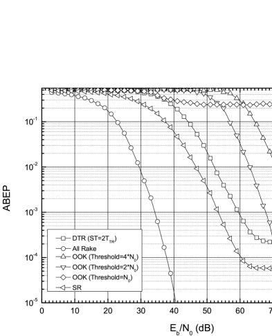
In Fig. 3, the ABEP is plotted against the Signal-to-Noise Ratio (SNR), defined as where denotes the transmitted symbol’s energy, assuming the CM1 channel model, which refers to the line of sight (LOS) case in residential environments [13]. Considering the OOK scheme, and since specifying the optimum threshold for the OOK receiver is beyond the scope of this paper, its performance was examined for three different decision thresholds, i.e. N0, 2N0 and 4N0, revealing the behavior of this receiver with respect to that threshold. The OOK receiver’s performance approaches that of the SR’s one only for high values of the SNR, where the received energy within a time window is adequate for deciding whether a signal has been transmitted or not.
The SR offers a comparable performance to that of DTR. This is a result of the fact that the data detection of a symbol in DTR scheme is affected by the correct detection of the previous one, which may result in the propagation of errors. On the other hand, in the SR scheme the detection of each symbol is independent from the previous one. For the case of the DTR and SR schemes the error floor is caused by the ISI.
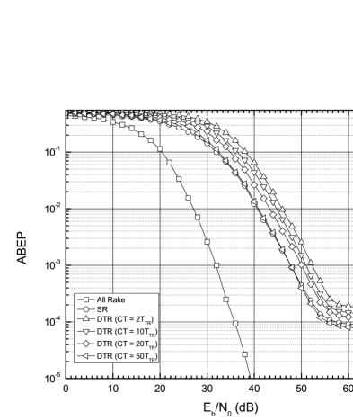
The results presented in Fig. 4 are based on CM2 channel model, which refers to non line of sight (NLOS) case [13]. The performance degradation of all systems is noticeable compared to CM1 and is a consequence of the severe scattering from which the signal suffers as we refer to a NLOS environment. Moreover, the performance of DTR is theoretically affected by the coherence time of the channel [14] as the data detection in DTR is affected by the resemblance of two consecutive channel responses. For instance, when transmitting four symbols and assuming a channel coherence time of two symbols, the channel response will differ between the second and the third symbol, affecting the autocorrelation operation at the receiver and hence the error performance. On the other hand, the SR scheme is not affected by this assumption, since the reference pulse is directly constructed by the same received signal. However, the performance of DTR is practically not affected, since usually the time interval between the pulses is in the order of , while the coherence time is in the order of .
The results are different for extreme NLOS multipath channels with significant RMS delay spread (e.g. CM3 and CM4), where the strong multipath components do not coincide with the first arriving ones, which results in a performance degradation for SR. Therefore, in order to improve the performance of the proposed structure, the duration of the transmitted pulse must be increased in order to take advantage of the spread energy. For example, considering the CM4 channel, a pulse duration of nsec cannot result in an ABEP lower than 0.1, while better performance can be achieved with nsec, e.g. ABEP= for SNR=27dB.
IV CONCLUSIONS
An alternative transceiver for UWB applications was introduced, called Self Reference (SR) UWB transceiver, which uses a modified replica of the received signal itself as reference pulse, resulting in double data rates compared to TR schemes. The proposed scheme eliminates the need for delay lines at the receiver side, as well as the need for channel estimations, resulting in lower complexity and power savings. The performance of the SR scheme was investigated in HF channels, showing that it offers a better or comparable performance to that of DTR, depending on the channel conditions.
References
- [1] C. Snow, L. Lampe, and R. Schober, “Performance Analysis and Enhancement of Multiband OFDM for UWB Communications,” IEEE Trans. Wireless Commun., vol. 6, no. 6, pp. 2182–2192, June 2007.
- [2] D. Cassioli, M. Z. Win, F. Vatalaro and A. F. Molisch, “Low Complexity Rake Receivers in Ultra-Wideband Channels,” IEEE Trans. Wireless Commun., vol. 6, pp. 1265-1275, no. 4, April 2007.
- [3] R. Hoctor and H. Tomlinson, “Delay-hopped transmitted-reference RF communications,” IEEE UWBST, pp. 265-269, 2002, Baltimore, MD.
- [4] Y. Chao and R. A. Scholtz, “Ultra–Wideband Transmitted Reference Systems”, IEEE Trans. on Vehic. Techn., vol. 54, pp. 1556–1569, Sept. 2005.
- [5] T. Q. S. Quek and M. Z. Win, “Analysis of UWB Transmitted–Reference Communications Systems in Dense Multipath Channels”, IEEE J. Sel. Areas Commun, vol. 23, pp. 1863–1874, no. 9, Sept. 2005.
- [6] Romme, J. and K. Witrisal, “Transmitted-reference UWB systems using weighted autocorre-lation receivers,” IEEETrans. on Microwave Theory and Techniques, Vol. 54, No. 4, 1754–1761, Apr. 2006.
- [7] M. Casu and G. Durisi, “Implementation aspects of a transmitted-reference UWB receiver”, Wirel. Commun. Mob. Comput., vol. 5, pp. 537 2005.
- [8] Y. L. Chao and R. A. Scholtz, “Optimal and suboptimal receivers for ultra-wideband transmitted reference systems,” Proc. IEEE Global Telecommun. (Globecom ’03), vol. 2, pp. 759–763, San Francisco, CA, Dec. 2003.
- [9] A. A. Saleh and R. A. Valenzuela, “A statistical model for indoor multipath propagation,” IEEE J. Select. Areas Commun., vol. 5, pp. 128–137, Feb. 1987.
- [10] J. R. Foerster, “Channel modeling sub-committee report final,” in Tech. Rep. P802.15 02/490r1, IEEE 802.15 SG3a, Feb. 2003.
- [11] H. A. Wittlinger, “Absolute Value Circuit,” Patent No. US 6,724,233 B1, Apr. 2004.
- [12] S. S. Ghassemzadeh, L. J. Greenstein, A. Kavcic, T. Sveinsson and V. Tarokh, ”UWB indoor path loss model for residential and commercial buildings”, Proc. of. VTC 2003-Fall, vol 5, pp. 3115-3119.
- [13] A. F. Molisch, D. Cassioli, C. Chong, S. Emami, A. Fort, B. Kannan, J. Karedal, J. Kunish, H. G. Schantz, K. Siwiak and M. Z. Win, “A Comprehensive Standardized Model for Ultrawideband Propagation Channels,” IEEE Trans. on Antennas and Propagation, vol. 54, pp. 3151-3159, 11 Nov. 2006.
- [14] J. D. Choi and W. E. Stark, “Performance of ultra-wideband communications with suboptimal receivers in multipath channels,” IEEE J. Select. Areas Commun., vol. 20, no. 9, pp. 1754 - 1766, Dec. 2002.