Asymmetric non-linear response of the quantized Hall effect
Abstract
An asymmetric break-down of the integer quantized Hall effect is investigated. This rectification effect is observed as a function of the current value and its direction in conjunction with an asymmetric lateral confinement potential defining the Hall-bar. Our electrostatic definition of the Hall-bar via Schottky-gates allows a systematic control of the steepness of the confinement potential at the edges of the Hall-bar. A softer edge (flatter confinement potential) results in more stable Hall-plateaus, i. e. a break-down at a larger current density. For one soft and one hard edge the break-down current depends on the current direction, resembling rectification. This non-linear magneto-transport effect confirms the predictions of an emerging screening theory of the IQHE.
pacs:
73.20.-r, 73.50.Jt, 71.70.DiThe discovery of the integer quantized Hall effect (IQHE) v. Klitzing et al. (1980) in a two-dimensional electron system (2DES) subject to a perpendicular magnetic field opened a wide research field in solid state physics, which became a paradigm since then Sarma and Pinczuk (1997). In spite of many experimental Ahlswede et al. (2001); Ilani et al. (2004); Horas et al. (2008); Siddiki et al. (2009) and theoretical Laughlin (1981); Halperin (1982); Büttiker (1986) efforts our understanding of the IQHE is still far from being complete. The conventional theories Laughlin (1981); Büttiker (1986); Kramer et al. (2003) can successfully describe the main features of the IQHE, namely the existence of extended Hall-plateaus and their extremely accurate quantized resistance values. Relying on a single-particle picture they fail to give a comprehensive description of many experimental observations on a more detailed level. These original edge or bulk theories disregard the classical Hartree-type (direct) Coulomb-interaction within the 2DES altogether Laughlin (1981); Halperin (1982); Büttiker (1986). The bulk theories assume the current to flow through the entire Hall-bar Kramer et al. (2003). Based on material properties such as disorder they predict localized states. The edge-theories describe the Hall-plateaus by assuming current flow only along the edges of the Hall-bar Büttiker (1986). An explanation of the transition region between plateaus requires the additional assumption of localized bulk states (as predicted within the bulk theories). A newer approach disregards disorder but includes the direct Coulomb-interaction between electrons moving in the confinement potential in a non self-consistent manner Chklovskii et al. (1992). Building on this model a screening theory emerged. It is based on self-consistent calculations Lier and Gerhardts (1994) and in addition considers disorder as well as the quantum mechanical wave functions of the electrons Siddiki and Gerhardts (2004); Siddiki (2007, 2009). For the Fermi-energy approximately centered in between two adjacent Landau-levels the screening theory predicts, that the current is carried by incompressible regions (strips) extending along the Hall-bar, hence replacing the edge-channels. Since back-scattering is absent within an incompressible region this explains the observation of the Hall-plateaus. Moreover, this self-consistent approach allows predictions going beyond the scope of the conventional theories, for example by taking into account the exact shape of the confinement potential or explicitly considering the non-linear transport regime. Effects based on the electron spin such as exchange interaction are not taken into account here, but can be included Siddiki (2008).
In this letter we discuss non-linear magneto-transport measurements in the framework of the screening theory. We experimentally investigate the current induced break-down of the IQHE in gate-defined Hall-bars with laterally asymmetric confinement potentials. In detail, we demonstrate a situation, in which dissipation-less current only exists in one of the two possible current directions. In agreement with the screening theory this rectification of the IQHE occurs in a wide range of parameters such as the mobility, charge carrier density and Hall-bar width, as long as disorder effects do not dominate the formation of incompressible strips Siddiki (2009).
Our Hall-bars are electrostatically defined by means of metallic Schottky-gates produced by electron-beam lithography on the surfaces of high mobility AlGaAs / GaAs-heterostructures containing 2DESs 110 nm beneath the surface. This field-effect method allows to define Hall-bars with extremely smooth and selectively tunable confinement potentials. A typical gate layout is displayed in the SEM-picture of Fig. 1a.
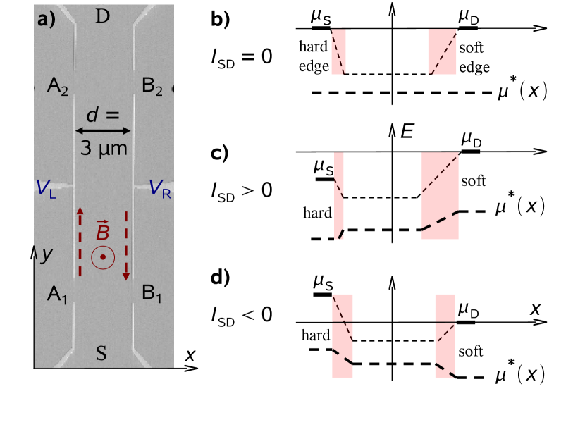
A constant dc current is impressed between the source (S) and drain (D) contacts, while four more ohmic contacts A1, A2 and B1, B2 are used as voltage probes. The Hall-resistance is obtained measuring the voltage drop between contacts A1 and B1 or A2 and B2, while the longitudinal resistance is measured with A1 and A2 or B1 and B2. For simplicity we will not specify which of these combinations of contacts are used in the following, given that our measurements are roughly independent of it. In order to create a laterally asymmetric confinement potential we apply different gate voltages and along the two sides of the Hall-bar, while the three gates on each side are always on equal potential. In all measurements shown here is perpendicular to the 2DES and points upwards, thus defining left-handed chirality, as sketched in Fig. 1a for the linear response case (dashed arrows indicate the direction that electrons move in equilibrium). corresponds to while the drain contact is always grounded (for the measurements shown in this letter). Figs. 1b, 1c and 1d sketch the energy of the relevant Landau-level (thin dashed line) for (Fig. 1a), (Fig. 1b) and (Fig. 1c) as predicted by the screening theory for the Hall-plateaus Siddiki (2009). The relevant Landau-level is the one, which is pinned to the chemical potentials at the edges of the Hall-bar. Also shown is the electro-chemical potential (fat dashed line) across the Hall-bar, which includes the effect of a non-zero current, i. e. the non-equilibrium case. The shaded areas mark the width of incompressible regions and will be discussed below.
We have performed measurements on five different samples with Hall-bar width of 3 m or 10 m and mobilities of , , and on the wafers I, II, and III, respectively. Here, we only present data measured on wafers I and III at a temperature of K. However, all our data taken so far confirm the results discussed below.
Fig. 2
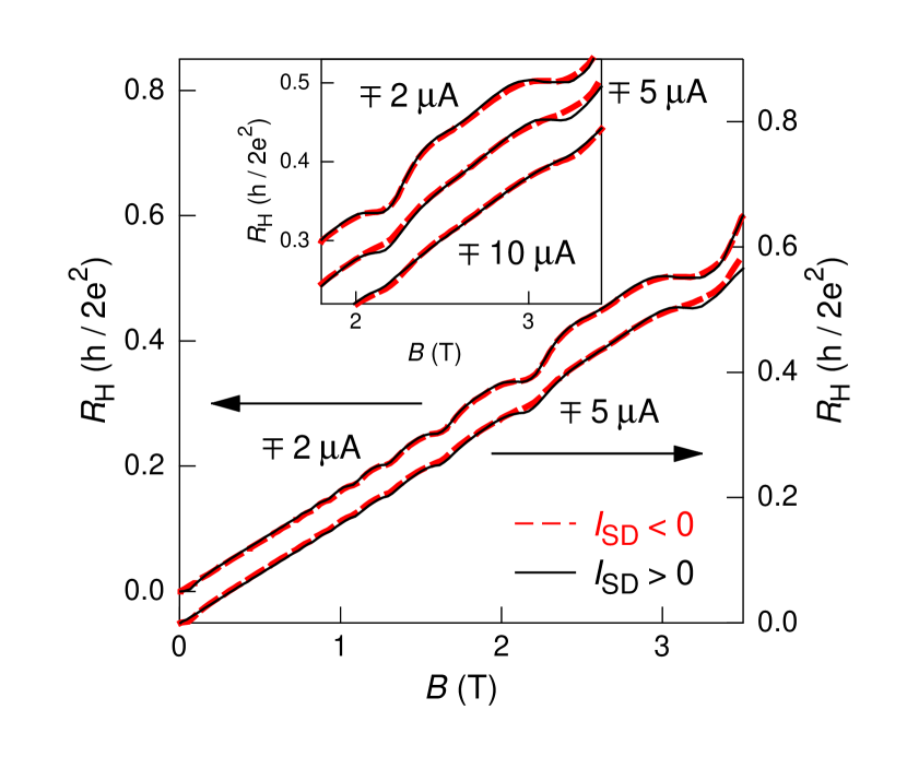
displays the measured Hall-resistance of a Hall-bar realized in wafer I (m, ) as a function of the perpendicular magnetic field T. The gate voltages are V and V. They create a harder confinement potential on the left hand side (lhs) of the Hall-bar compared to the relative soft rhs edge (see Fig. 1b). Note, that V just allows complete depletion of the 2DES beneath any of the biased gates. The Hall-curves displayed in Fig. 2 are measured at A (lhs y-axis) and A (rhs y-axis). Part of the curves, namely in the region of filling factors and are shown again in the inset of Fig. 2, where we also added data for A (curves for A and A are vertically shifted). For A the Hall-plateaus are well established, while they are pretty much smeared out for A, independent of the current direction. This observation can be attributed to the well known break-down of the Hall-effect, usually explained (within the edge channnel models) by scattering between (many) edge channels Güven et al. (2002). Interestingly, for the intermediate current value of A the break-down is more pronounced for one of the two current directions, namely .
Exactly this behavior is predicted by the screening theory Siddiki (2009); within this calculation scheme the current induced break-down of the Hall-effect is caused by inelastic scattering between compressible regions (Joule heating) Kanamaru et al. (2006). Essentially the width of the incompressible strips decreases as the current is increased. However, as long as there exists at least one incompressible strip across the Hall-bar, dissipation less current is possible resulting in the plateau-value of . In agreement with the screening theory we assume two incompressible strips, just one on each edge of the Hall-bar Siddiki and Gerhardts (2004). On the one hand, the asymmetric confinement causes the incompressible strip on the softer edge to be wider than the one on the harder edge (for Fig. 2 the lhs edge), as sketched in Fig. 1b. On the other hand, a large current generally results in a widening (narrowing) of the incompressible strip at the edge of the higher (lower) electrochemical potential (Figs. 1c and 1d) Siddiki (2009). For the higher electrochemical potential on the softer edge (Fig. 1c), the result is therefore a very narrow incompressible strip on the hard edge and a very wide incompressible strip on the soft edge. The direct consequence is a more stable incompressible strip (on the soft edge) and a wider Hall-plateau at the onset of the break-down regime. For the data shown in Fig. 2 this situation is reached for . For the opposite current direction the two effects (namely current versus asymmetry induced widening or narrowing of incompressible strips) cancel out and, accordingly, the break-down is already observed for lower absolute values of the current (Fig. 1d).
Within this scenario it is possible to compensate a reversal of the lateral asymmetry of the confinement potential by reversing the direction of the impressed current. This prediction Siddiki (2009) is experimentally tested in Fig. 3,
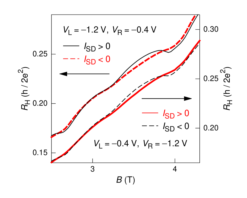
where we plot taken at m on the same wafer as above. Between the two sets of curves the asymmetry of the confinement potential is reversed by exchanging the soft and hard edges of the Hall-bar (while the magnetic field direction is unchanged). For the harder edge on the lhs of the Hall-bar (lhs axis, two curves on top) the Hall-effect is more stable for , as already observed in Fig. 2. In contrast, if the lhs edge is the softer one, the Hall effect is more stable for . As expected the general behavior stays unchanged, whenever we inverse both, the direction of the current and the direction of the lateral confinement potential. However, a reversal of only one of the two quantities near the onset of the break-down of the IQHE causes a drastic change in the width of the Hall-plateaus. We interpret this behavior as a rectification of the IQHE.
Fig. 4
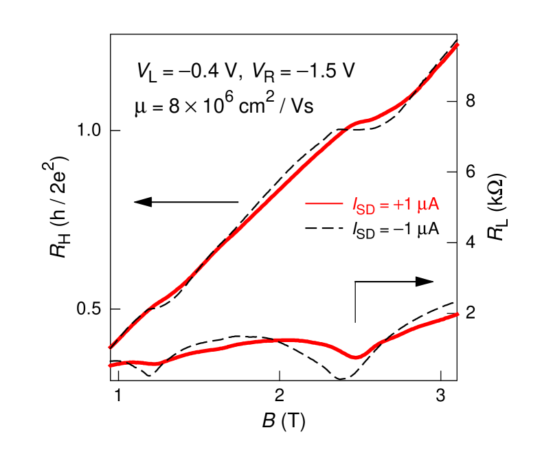
plots an example of the same behavior, but observed on wafer III with a much higher mobility of and a Hall-bar width of m measured at A. Here we apply V and V defining the harder edge on the rhs of the Hall-bar. Note, that the smaller absolute value of the break-down current observed in the high mobility sample might be explained by a smaller width of this Hall-bar. As expected the break-down of the Hall-effect is more pronounced for positive current, causing a higher chemical potential at the lhs edge of the Hall-bar. In Fig. 4 we additionally display the longitudinal resistance (rhs y-axis). It shows a break-down behavior in accordance to the data.
We observe the same behavior in a wide range of mobilities, charge carrier densities, Hall-bar widths and contact combinations. While here we show only a small selection of our data, we have performed many control measurements always leading to the same systematic result, namely rectification of the IQHE in a Hall-bar with an asymmetric lateral confinement potential as a function of the direction of the impressed current (at the onset of the break-down of the IQHE).
In the following we discuss our results in light of conventional theories versus the screening theory of the IQHE. Both, the original bulk and edge theories fail to describe the experimentally observed smooth transition regions between the plateaus of the Hall-resistance (and the corresponding finite longitudinal resistance) in a self contained way. Instead the transition between Hall-plateaus is phenomenologically explained by assuming broadening of the Landau-levels and corresponding narrowing of the Hall-plateaus. Hence, one would expect a narrowing of the Hall-plateaus as the mobility is decreased (and the disorder is increased). However, in experiments the opposite behavior is observed, namely the plateaus become wider as the mobility is decreased. To heal this discrepancy it is then –again phenomenologically– assumed, that disorder induced localization causes an insulating bulk state. The edge theories take, in addition, the confinement potential into account, as the edge states are a direct result of the Landau-levels cutting the Fermi-energy at the edges of the Hall-bar. However, no detailed assumptions are made regarding the shape of the confinement potential.
In our experiments, we observe the effect of an impressed current on the Hall-resistance (altering the transition regions between the plateaus) as a function of the lateral shape of the confinement potential. In this regime, we cannot expect the conventional theories to explain our findings. Moreover, calculations within these conventional models are done in the linear response regime, while here we use large currents clearly putting us out of the linear response regime.
The screening theory is based on numerical calculations of the exact shape of the confinement potential by taking the direct Coulomb-interaction between charge carriers as well as their quantum mechanical properties into account Siddiki and Gerhardts (2004); Siddiki (2009). In contrast to the conventional theories, the screening theory allows self-consistent numerical calculations even in the non-linear response regime, which results in predictions at the onset of the break-down regime of the IQHE. The observed rectification of the IQHE at the onset of its break-down go beyond the scope of conventional theories. Our results qualitatively confirm the predictions of the screening theory.
It should be noted that the present form of the screening theory does not account for the local temperature (and local heating effects) in a self-consistent way. However, a reasonable prescription for such a calculation is already given in the literature Kanamaru et al. (2006). In this calculation scheme a large impressed current melts (narrows) the incompressible strips, finally leading to the experimentally observed breakdown. While the screening theory predicts the width and location of incompressible strips omitting local heating effects, the additional assumption of local heating as treated in reference Kanamaru et al. (2006) results in a qualitative agreement with our experiments.
A. S. thanks D. Harbusch and D. Taubert for their technical support and J. P. Kotthaus for trusting a theorist performing experiments in his institute. Financial support by the German Science Foundation via SFB 631, the Germany Israel program DIP and the German Excellence Initiative via the ”Nanosystems Initiative Munich (NIM)” is gratefully acknowledged.
References
- v. Klitzing et al. (1980) K. v. Klitzing, G. Dorda, and M. Pepper, Phys. Rev. Lett. 45, 494 (1980).
- Sarma and Pinczuk (1997) S. D. Sarma and A. Pinczuk, in Perspectives in Quantum Hall Effects (Wiley, New York, 1997).
- Ahlswede et al. (2001) E. Ahlswede, P. Weitz, J. Weis, K. von Klitzing, and K. Eberl, Physica B 298, 562 (2001).
- Ilani et al. (2004) S. Ilani, J. Martin, E. Teitelbaum, J. H. Smet, D. Mahalu, V. Umansky, and A. Yacoby, Nature 427, 328 (2004).
- Horas et al. (2008) J. Horas, A. Siddiki, J. Moser, W. Wegscheider, and S. Ludwig, Physica E Low-Dimensional Systems and Nanostructures 40, 1130 (2008), eprint arXiv:0707.1142.
- Siddiki et al. (2009) A. Siddiki, J. Horas, J. Moser, W. Wegscheider, and S. Ludwig, Europhysics Letters 88, 17007 (2009), eprint 0905.0204.
- Laughlin (1981) R. B. Laughlin, Phys. Rev. B 23, 5632 (1981).
- Halperin (1982) B. I. Halperin, Phys. Rev. B 25, 2185 (1982).
- Büttiker (1986) M. Büttiker, Phys. Rev. Lett. 57, 1761 (1986).
- Kramer et al. (2003) B. Kramer, S. Kettemann, and T. Ohtsuki, Physica E 20, 172 (2003).
- Chklovskii et al. (1992) D. B. Chklovskii, B. I. Shklovskii, and L. I. Glazman, Phys. Rev. B 46, 4026 (1992).
- Lier and Gerhardts (1994) K. Lier and R. R. Gerhardts, Phys. Rev. B 50, 7757 (1994).
- Siddiki and Gerhardts (2004) A. Siddiki and R. R. Gerhardts, Phys. Rev. B 70, 195335 (2004).
- Siddiki (2007) A. Siddiki, Phys. Rev. B 75, 155311 (2007).
- Siddiki (2009) A. Siddiki, EPL 87, 17008 (2009).
- Siddiki (2008) A. Siddiki, Physica E Low-Dimensional Systems and Nanostructures 40, 1124 (2008), eprint arXiv:0707.1123.
- Güven et al. (2002) K. Güven, R. R. Gerhardts, I. I. Kaya, B. E. Sagol, and G. Nachtwei, Phys. Rev. B 65, 155316 (2002).
- Kanamaru et al. (2006) S. Kanamaru, H. Suzuuara, and H. Akera, J. Phys. Soc. Jpn. 75 (2006), and proceedings EP2DS-14, Prague 2001.