Tuning the atomic and domain structure of epitaxial films of multiferroic BiFeO3
Abstract
Recent works have shown that the domain walls of room-temperature multiferroic BiFeO3 (BFO) thin films can display distinct and promising functionalities. It is thus important to understand the mechanisms underlying domain formation in these films. High-resolution x-ray diffraction and piezo-force microscopy, combined with first-principles simulations, have allowed us to characterize both the atomic and domain structure of BFO films grown under compressive strain on (001)-SrTiO3, as a function of thickness. We derive a twining model that describes the experimental observations and explains why the 71∘ domain walls are the ones commonly observed in these films. This understanding provides us with a new degree of freedom to control the structure and, thus, the properties of BiFeO3 thin films.
Magnetoelectric multiferroics exhibit coupled electric and magnetic orders, which might lead to a variety of novel devices that would benefit from the fact that the magnetization (polarization) of these materials can be controlled by means of an electric (magnetic) field Ram07 . For practical devices, multiferroics are preferred in thin film form. Moreover, the strain induced by the mismatch between the film and the substrate lattice parameters can sometimes be used to tune the film properties with respect to the bulk Wan03 .
Bismuth Ferrite, BiFeO3 (BFO), is one of the few multiferroics that orders above 300 K and, thus, one of the most promising ones Cat09 . The ferroelectric properties of BFO are very robust, and it displays record polarization values of about 100 C/cm2. Since the ground state of bulk BFO is rhombohedral (space group R3c), symmetry arguments suggest that the thin films grown on cubic substrates under compressive epitaxial strain should be monoclinic (space group Cm or Cc, depending on whether the O6 octahedra rotations are clamped by the substrate or not, respectively). Indeed, several authors Xu05 ; Bea07 ; Kim08 ; Jan08 have reported a monoclinic unit cell that is similar to that of strong piezoelectric PbZr1-xTixO3 (PZT) with 0.5 Noh99 . The proposed link between the strong piezoelectricity and the symmetry of the unit cell Bel00 , which allows the polarization to rotate, adds to the interest of BFO films Jan08 .
Beyond their intrinsic properties, BFO films are currently receiving renewed attention because of the novel functionalities observed to occur at domain walls (DWs). Indeed, recent works have shown that some BFO DWs are highly conductive Sei09 , and that the DW density controls the magnitude of the (exchange bias) coupling between BFO and other (metallic) layers in complex heterostructures Mar08 . It is thus of prime importance to achieve control of the domain structures and understand their formation. In contrast, it is striking to note the scarcity, and lack of agreement, of experimental information on the atomic structure of the films and its evolution with thickness Xu05 ; Kim08 ; Jan09 . Indeed, we believe that a complete picture of the structure of these films does not exist yet.
We have grown BFO thin films on SrRuO3-buffered SrTiO3 (STO) substrates, and followed the unit cell distortion as a function of thickness during the first stages of strain relaxation. Our c/a ratios are consistent with those in Ref.Kim08, . Additionally, we have been able to resolve the monoclinic distortion and measure the evolution of the full unit cell. The comparison of the experimental results with several structural models simulated ab initio allowed us to resolve the monoclinic space group (Cc) and atomic structure, as well as the polarization direction.
Several (001)-oriented BFO thin films with thickness ranging from 12 to 87 nm were grown on atomically flat, TiO2-terminated (001)-STO substrates with low miscut angle (0.1∘). Conductive layers of SrRuO3 with a thicknesses of 5 nm were deposited in between the substrate and the BFO layer. The BFO films were grown by pulsed laser deposition, assisted by reflective high energy electron diffraction (RHEED), using a KrF excimer laser (= 248 nm). The deposition was performed at 670∘C in an oxygen pressure of 0.3 mbar. After deposition, the films were cooled down slowly to room temperature under an oxygen pressure of 100 mbar.
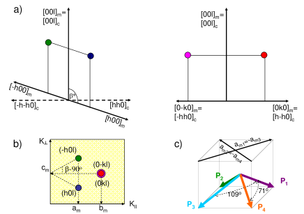
The evolution of the crystallographic distortion with thickness was investigated by mapping the reciprocal space using x-ray diffraction (XRD) from lab (out-of-plane) and synchrotron (in-plane) sources. Due to the epitaxy, which fixes the [001] direction in reciprocal space to be perpendicular to the substrate surface, the twelve possible monoclinic domains are reduced to four and the reciprocal space maps are significantly simplified (similar to the case of a crystal under an electric field Noh01 ). In particular, if all domains are present, looking at the areas around the substrate (hhl)c, which corresponds to the (h0l)m reflection in the monoclinic structure fn1 , one can extract the three lattice parameters and the monoclinic angle, as sketched in Fig. 1.
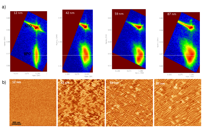
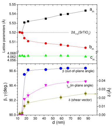
Typical reciprocal space maps (RSMs) around the (113)c STO substrate reflections for ultrathin ( 18 nm) and thin ( 18 nm) films are shown on Fig. 2a. The RSMs of the thinnest BFO films display a broad (113)c peak (using the pseudo-cubic notation), at the same K∥ (in-plane component of the scattering vector) of the substrate, showing that they are fully coherent with the substrate. The FWHM of these films agrees with what is expected for their thicknesses. There is thus no indication of unresolved splitting. The RSMs of thicker films display a splitting of the (113)pc BFO peak, as expected (see Fig. 1). The monoclinic lattice parameters extracted from these patterns are plotted in Fig. 3. Interestingly, shows no changes with increasing thickness. This is in agreement with the report by Kim et al. Kim08 , who showed that the lattice parameters of the strained films are constant below 100 nm, a puzzling and unexplained result. However, for thickness above 18 nm we observe a splitting of the in-plane parameter values and a 90∘, characteristic of a monoclinic distortion. Figure 3 reveals a gradual increase of the monoclinic distortion with thickness. In addition, grazing incidence XRD (GID) has shown that the in-plane pseudo-cubic angle, is, indeed, different from the out-of-plane angle , and that such a difference decreases with increasing thickness ( in the relaxed structure). Interestingly, the deviation of and from the value of 2 (i.e., the fully coherent case) is symmetric.
First-principles simulations fn2 allowed us to ratify these results and gain further insight into the atomic structure of the BFO films. It has been shown that ferroelectric thin films can be successfully studied by simulating the corresponding bulk material subject to elastic boundary conditions that mimic the epitaxial constraints imposed by the substrate. In this work we extend such an approach to make a distinction between the cases of ultra-thin and thin films, for which we consider different elastic constraints. More precisely, in the ultra-thin (uth) case we assumed the film is strongly clamped by the substrate, and impose and =90∘. In contrast, in the thin (th) case we only imposed that the in-plane area be constrained to be . This allowed us to model the “ultra-thin” to “thin” transition evidenced by the experimental results of Fig. 3. On the other hand, in our simulations we considered two structural models, with and without rotations of the O6 octahedra, which correspond, respectively, to the Cc and Cm space groups.
Our simulations clearly indicate that the BFO films present significant O6 rotations and thus the Cc space group. Indeed, when allowing for O6 rotations we computed =1.0016 and =0.9981 for the splitting of in-plane lattice parameters, in good agreement with the experimental values of 1.0015 and 0.9980 derived from the data in Fig. 3. In contrast, when the O6 tiltings are clamped in the simulations, we obtained =1.0029 and =0.9968. The ratios follow the same pattern: the value computed with (without) O6 tiltings is about 1.07 (1.17), to be compared with the experimental result of approximately 1.04, which strongly suggests that even in the thinnest films the O6 rotations are not fully clamped by the substrate. These results provide a justification to first-principles studies of monoclinic BFO films in which a structural model with O6 rotations is adopted (see, e.g., Ref. hatt09, ). Additionally, for the calculated monoclinic angle we obtained =90.4∘, which is perfectly compatible with our experimental results, and we computed =1.0005, in agreement with our experimental observation that the lattice constant is weakly dependent on thickness. Finally, the computed polarization is very weakly affected by the uth-to-th transition: We obtained = 90 C/cm2, with in-plane and out-of-plane components of 59 C/cm2 and 68 C/cm2, respectively. The polarization forms an angle of about 11.6∘ with the body diagonal of the pseudocubic cell, being rotated towards the [001] direction.
Let us now describe the evolution of the domain structure. Analysis of the RSMs in Fig. 2 shows that the domain walls that prevail are the 71∘ ones (see Fig. 1c) in agreement with previous reports Chu07 . This is confirmed by grazing incidence diffraction (not shown here), as well as from PFM images (Fig. 2b). Out-of-plane PFM measurements show that all the films are polarized down, also in agreement with previous reports Chu07 . In Fig. 2b, in-plane PFM (IP-PFM) images of the same films are shown. In agreement with the XRD data, we observe a clear evolution of the domain pattern. For the thinnest films, no contrast is detected on the IP-PFM images. IP-PFM images for intermediate films show a clear stripe-like pattern. These stripes indicate four polarization variants, which are in good agreement with rhombohedral-like monoclinic distortions Zav06 (see figure 1c) and with the RSM maps. We observe that the number of variants decreases from four to two variants with further increasing thickness, allowing for longer stripes for the thicker films. Several works have already shown two-variant stripe domains for (001)-oriented BFO films, by using miscut STO substrates Das06 ; Jan09 or orthorhombic substrates Chu06 . The origin of this reduction of polarization orientations in BFO films was reported to be the step-flow growth and the substrate anisotropy, respectively. Since the growth mode as well as the substrate miscut in all our films are the same, our results point to yet a different mechanism.
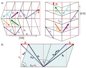
All this evidence fits a simple but powerful model by which the domain formation enables and controls the monoclinic distortion of the unit cell. Figure 4a shows how twinning reduces the in-plane strain introduced by the pseudo-cubic angle, (characteristic of the monoclinic distortion). Two pairs of twins, coherent along [100] (v1) or along [010] (v2), can form. It can also be seen that, in order to do that, the in-plane lattice parameters of the film, and , deviate equally from the fully strained values of , i.e., and , as sketched in Fig. 4b. The magnitude of the shear vector , therefore, determines both and , which split symmetrically with increasing thickness (see Fig. 3). As a result, the in-plane area of the film is unchanged with respect to the fully coherent film, which in turn seems compatible with the observation that the lattice parameter does not vary during strain relaxation (for thicknesses up to 100 nm). A more subtle result of this relaxation process is that the symmetry of film unit cell is actually lower than monoclinic; indeed, it can be seen from Fig. 4b that the angle between and is given by , and thus different from 90∘. A very similar twining mechanism with symmetry lowering has been found in thin films of TbMnO3 grown on (001)-STO substrates Sri09 , which suggests it may be typical of low symmetry perovskites on cubic substrates. As observed in figure 4a), the two pairs of variants, 90∘ rotated from each other, are in agreement with the PFM maps of the 42 and 59 nm films and give rise to both 71∘ and 109∘ walls. Even though both nucleate with equal probability in the growing film, on a low miscut substrate, because of the relatively large strain energy store at the boundary between them, for thicker films (and therefore larger strain energy at those boundaries) one of the two variants will be preferred, as observed in the thicker 89 nm film. In the presence of a substrate miscut, the steps can indeed determine which of the two variant is present Jan09 , but this will happen in exact substrates provided that the films have enough time to relax.
In summary, we have observed clear trends in the evolution with thickness of the structure and microstructure of BiFeO3 films on (001)-SrTiO3 substrates. We have shown that the lattice parameters and the film symmetry do not result simply from the mismatch with the substrate, but also from the occurrence of a particular twinning that allows for the observed monoclinic distortion. This twinning model explains why the 71∘ domain walls are so often observed in atomically flat films on (001)-SrTiO3. Such an effect provides us with a new degree of freedom for tuning the structural and physical properties of the thin films. Our results suggest that the physics behind the effects of epitaxial strain is richer than usually thought, and that traditional thermodynamic phase diagrams and first-principles models need to be complemented with knowledge of the domain structure in order to reach a full understanding of the materials behavior.
We are grateful to Gijsbert Rispens and Sriram Venkatesan for useful discussions. This is work was partly funded by MaCoMuFi (Grant No. STREP_FP6-03321), the Spanish Government (Grants No. FIS2006-12117-C04-01 and No. CSD2007-00041) and the Dutch agencies NWO and FOM. We made use of the facilities of the BSC-CNS and CESGA supercomputing centers.
References
- (1) R. Ramesh and N.A. Spaldin, Nature Materials 6, 21 (2007)
- (2) J. Wang et al., Science 299, 1719 (2003)
- (3) G. Catalan and J.F. Scott, Advanced Materials 21, 2463 (2009)
- (4) ] G. Xu, H. Hiraka, G. Shirane, J. Li, J. Wang, and D. Viehland, Appl. Phys. Lett. 86, 182905 (2005).
- (5) H. Bea et al. Philosophical Magazine Lett. 87, 165 (2007)
- (6) D.H. Kim, Appl. Phys. Lett. 92, 012911 (2008);
- (7) H. W. Jang, S. H. Baek, D. Ortiz, C. M. Folkman, R. R. Das, Y. H. Chu, P. Shafer, J. X. Zhang, S. Choudhury, V. Vaithyanathan, Y. B. Chen, D. A. Felker, M. D. Biegalski, M. S. Rzchowski, X. Q. Pan, D. G. Schlom, L. Q. Chen, R. Ramesh, and C. B. Eom, Phys. Rev. Lett. 101, 107602 (2008).
- (8) B. Noheda, D. E. Cox, G. Shirane, J. A. Gonzalo, L. E. Cross, S. E. Park, Appl. Phys. Lett. 74, 2059 (1999)
- (9) L. Bellaiche et al. Phys. Rev. Lett. 84 5427 (2000)
- (10) J. Seidel et al. Nature Materials 8, 229 (2009)
- (11) L.W. Martin et al. Nano Letters 8, 2050 (2008)
- (12) H. W. Jang, D. Ortiz, S.-H. Baek, C. M. Folkman, R. R. Das, P. Shafer, Y. Chen, C. T. Nelson, X. Pan, R. Ramesh, and C.-B. Eom, Adv. Mater. 21, 817(2009)
- (13) B. Noheda, D. E. Cox, G. Shirane, S.-E. Park, L. E. Cross, and Z. Zhong, Phys.n Rev. Lett. 86, 3891 (2001)
- (14) The indexes are with respect to the Cm space group, as in Ref. Noh01, . With XRD we are not sensitive to oxygen rotations as thus we cannot distinguish between Cc and Cm. ett. 90, 252906 (2007).
- (15) The technical details for our simulations of BFO are standard; see e.g. O.E. González-Vázquez and J. Íñiguez, Phys. Rev. B 79, 064102 (2009). We checked our calculations reproduce basic results for BFO in the literature (as, e.g., the related ones in Ref. hatt09, ). The effect of epitaxial strain was simulated by imposing appropriate constraints in our structural relaxations: const. and for the ultra-thin limit, and =const. in the thin limit. The constraint is chosen to mimick a 3% contraction of the in-plane area with respect to the bulk value, as it approximately corresponds to BFO on (001)-STO.
- (16) A.J. Hatt, N.A. Spaldin, and C. Ederer, arXiv:0909.4979
- (17) Y. H. Chu, T. Zhao, M. P. Cruz, Q. Zhan, P. L. Yang, L. W. Martin, M. Huijben, C. H. Yang, F. Zavaliche, H. Zheng, and R. Ramesh, Appl. Phys. Lett. 90, 252906 (2007)
- (18) F. Zavaliche, S. Y. Yang, T. Zhao, Y. H. Chu, M. P. Cruz, C. B. Eom, and R. Ramesh, Phase Transitions 79, 991 (2006).
- (19) R. R. Das, D. M. Kim, S. H. Baek, C. B. Eom, F. Zavaliche, S. Y. Yang, R. Ramesh, Y. B. Chen, and X. Q. Pan, Appl. Phys. Lett. 88, 242904 (2006)
- (20) Y. H. Chu, Q. Zhan, L. W. Martin, M. P. Cruz, P. L. Yang, G. W. Pabst, F. Zavaliche, S. Y. Yang, J. X. Zhang, L. Q. Chen, D. G. Schlom, T. B. Wu, and R. Ramesh, Adv. Mater., 18, 2307 (2006).
- (21) Sriram Venkatesan et al. Phys. Rev. B (to be published)