Fast Beam Conditions Monitor BCM1F for the CMS Experiment
Abstract
The CMS Beam Conditions and Radiation Monitoring System, BRM, will support beam tuning, protect the CMS detector from adverse beam conditions, and measure the accumulated dose close to or inside all sub-detectors. It is composed of different sub-systems measuring either the particle flux near the beam pipe with time resolution between nano- and microseconds or the integrated dose over longer time intervals. This paper presents the Fast Beam Conditions Monitor, BCM1F, which is designed for fast flux monitoring measuring both beam halo and collision products. BCM1F is located inside the CMS pixel detector volume close to the beam-pipe. It uses sCVD diamond sensors and radiation hard front-end electronics, along with an analog optical readout of the signals. The commissioning of the system and its successful operation during the first beams of the LHC are described.
keywords:
LHC , CMS , beam conditions , sCVD diamonds , radiation hard sensors1 Introduction
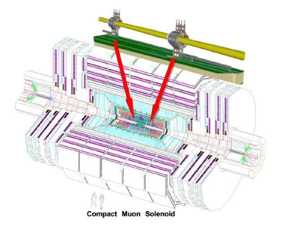
The CMS experiment [1] at LHC [2] will be situated in an unprecedentedly high radiation field. The LHC is designed to run with 362 MJ of stored energy in one beam and with proton intensities of more than 1014 per beam. These beams will generate a continuous flux of halo particles near the beam-pipe and when colliding also interaction secondaries, predominantly at small polar angles. The collected dose will be largest for the innermost detectors, which are therefore designed with very high radiation tolerance.
However, also short term losses of the beams may cause serious damage to detector elements, in particular to front-end electronics due to large ionisation. In addition, the innermost detectors need a sufficiently low occupancy level for successful data taking.
To monitor the particle fluxes near the beam-pipe and the radiation level in the sub-detectors, beam conditions and radiation monitors, BRM [1, 3], are installed in the CMS detector. Several slow systems of BRM will be used to measure the accumulated dose near the volume of all sub-detectors. These measurements are necessary to understand potential longer term damage to detector elements.
Particle flux monitors are installed close to the beam-pipe. Two such monitors measure the integral particle flux over half an orbit or over a bunch train using the signal current in polycrystalline small diamond sensors and integrate it over about 40 s and 5 s, respectively. These fluence measurements will assist beam tuning, indicate critical beam halo conditions for the inner detectors and initiate LHC beam aborts when conditions are such that detectors might be endangered. These systems are described in detail in Ref. [4]. Other LHC experiments also installed beam condition monitors using polycrystalline diamond sensors [5].
The Fast Beam Conditions Monitor, hereafter referred to as BCM1F, will be sensitive to very fast changes of the beam conditions and provide diagnostics with a time resolution better than the time between bunch crossings, hence, for example, being able to flag problematic beam conditions resulting in bursts of beam loss over very short periods of time. Such beam losses are considered to be one of the principle damage scenarios for CMS detector components. In addition, it will store real-time data to allow post-mortem analyses in the case of beam accidents.
2 BCM1F System Overview
BCM1F uses single-crystal CVD111Chemical Vapor Deposition diamond sensors, hereafter denoted as sCVD, for particle detection. Sensors made of sCVD are sufficiently fast to match the time resolution requirements, and small enough to be inserted into areas close to key detector components without adding substantial material or services. Four sCVD sensors, each with a volume of 550.5, are positioned in a plane perpendicular to the beam-pipe on each side of the IP at a distance of about 1.8 m and at a radius of 4.5 from the nominal beam position, as sketched in Figure 1.
The position of the BCM1F is chosen to be optimal in terms of time separation between ingoing and outgoing particles from the IP. Relativistic particles need about 6 to move between one of the detector planes and the IP. Hence, gated rate measurements of the BCM1F will allow to separate the fluxes from both beam halo of each direction and interactions products.
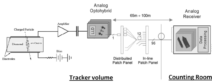
Each sensor is connected to a radiation hard preamplifier. Its output signal is transmitted to the counting room over an analog optical link as shown schematically in Figure 2.
Since neither cooling nor slow control equipment are available at the mounting positions, the modules must be operated with low power dissipation and should work over long periods without a re-adjustment of the calibration parameters.
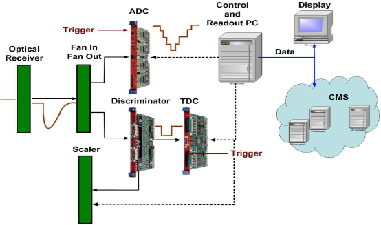
At the back-end of the readout in the counting room signals are digitized and processed in a PC. Flash ADCs, scalers and multi-hit recording TDCs allow e.g. to monitor counts as a function of time over an orbit. Test-pulses are used to check the functionality of the system. Rates, multiplicities, timing and coincidence information are monitored and stored independently of the CMS data acquisition.
3 sCVD Sensors
Outstanding properties, such as a very low leakage current with negligible temperature dependence, a fast signal response and radiation hardness, make CVD diamond sensors attractive for the locations close to the interaction region. In previous experiments polycrystalline diamond sensors have been successfully used as beam conditions monitors [6, 7] by measuring the currents created in the sensor by the crossing particles. However, integration over a certain time limits the time resolution of such devices. In addition, due to crystal defects the charge collection efficiency of polycrystalline CVD sensors is below 50% which may result in a signal-to-noise ratio not sufficient for the detection of minimum ionising particles, MIPs.
Here single crystal CVD diamond sensors are used. They are characterised by nearly 100% charge collection efficiency and allow to count MIPs. They are operated as solid state ionisation chambers by applying high voltage to thin metal plates on both sides of a sensor to create an electric field in the bulk, as shown in Figure 2. Signals from crossing charged particles are created due to the drift of electrons and holes released in the bulk material.
The sCVD sensors are of 55 area and 500 m thickness. They have been manufactured by Element Six [8] after a few years of development and research in collaboration with the CERN RD42 project [9]. A first application of an sCVD diamond sensor in a collider experiment was described in Ref. [10].
4 Sensor Tests
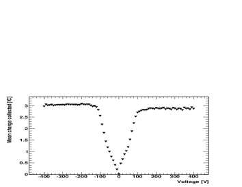
Before installation the sensors were tested in the laboratory. The leakage currents and signal response to electrons from a 90Sr source were measured for all diamond sensors before assembly. The leakage currents of the sensors are in the range of a few pico-Amperes. The signal amplitude, expressed as the average collected charge, is shown as a function of the bias voltage for both polarities in Figure 3 for one of the sensors. The signal amplitude increases for increasing bias voltage up to about 120 V, corresponding to a field strength of about 0.25 Vm-1, and is constant thereafter. The measurements for the other sensors show a very similar behavior. In a few cases slight differences in the signal size for different bias voltage polarities are observed. These sensors are operated with the polarity of the bias voltage giving the maximum signal yield.
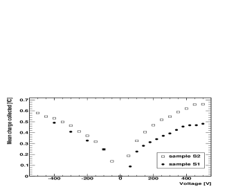
Two sample sensors were irradiated in a 60 proton beam at PSI up to a fluence of about 31014 protons per cm2, corresponding to a fluence of 17.51014 MIPs per [11]. The signal amplitude obtained from electrons of a 90Sr source is shown in Figure 3 for two sensors after irradiation. It drops to about 20% of the one measured with a non-irradiated sensor. Whereas in the non-irradiated sample the signal amplitude saturates already at about 0.25 Vm-1, in the irradiated sample no saturation is seen up to 1 Vm-1. Comparing these results to previous studies [11] of the performance of diamond sensors as a function of the fluence of 26 and 24 protons the hypothesis of enhanced damage at lower particle energies is supported. The fluence investigated here is approximately that expected at the location of the BCM1F detector over the baseline LHC program.
5 Readout Electronics
Each sensor is connected to a JK16 radiation hard amplifier ASIC [12]. The chip is fabricated in a commercial 0.25 m CMOS technology hardened by appropriate layout techniques.
Each channel comprises a fast trans-impedance preamplifier with an active feedback loop and an amplifier-integrator stage with 20 peaking time. An excellent noise performance is achieved by a careful adjustment of the feedback current through the gate voltage of the feedback FET. For a detector capacitance of 5 pF the measured noise amounts to about 700 electrons ENC in agreement with the specifications given in Ref. [12]. The measured charge gain is 20/fC.
The analog signals are transmitted to the counting room using an analog optical chain [13] developed for the CMS tracker. The preamplifier’s single-ended output is AC coupled to the custom-designed laser driver ASIC, which modulates the current of the edge-emitting laser diode. Single mode fibres from the pigtailed lasers are connected at the periphery of the tracker volume to an optical fan-in, which merges single fibres into a 12-fiber ribbon cable. In the counting room a corresponding ribbon connects directly to a 12-channel analog optical receiver card in a VME crate.
Minor modifications on the laser driver ASIC board were done to allow mounting in two opposite orientations of the laser diode, required by the minimal bending radius of the pigtail fibres. In contrast to the tracker application, for the BCM1F the gain and the laser diode bias current cannot be programmed via the foreseen I2C interface. Hence, attention was paid to choose the input polarity and the laser bias setting to preserve the dynamic range of the receiver side. In addition, the impacts of heat dissipation and the expected radiation dose on the laser diode performance degradation were taken into account. To ensure a small package size a piggy-back architecture was used for interconnecting and mounting the sensor, the amplifier and the analog optical hybrid boards on their carriage.
At the back-end side of the readout the optical signals are converted into electrical signals using an analog opto-receiver module. Its output signals are distributed by analog fan-outs to ADC inputs and to discriminators. A flash ADC performing 500 MS/s with 8 bit resolution, V1721 from CAEN, is used to digitise the signals. This module can be triggered internally or externally. It can read out in full data mode up to 45 consecutive beam orbits or a corresponding number of user definable time intervals. Data is written into a ring buffer and tagged with time stamps. It is read out via an on-board optical link and processed in a PC.
The discriminated signals are counted in all channels with a V260 scaler from CAEN and used for on-line displays of hit rates. In addition, they are digitised with multi-hit capable TDCs V767 from CAEN with 20 bit dynamic range and 0.8 ns-LSB resolution. The TDCs and the scalers are read out via a VME-bridge. They will allow orbit-by-orbit counts to be obtained as a function of time for a detailed monitoring of beam halo and interaction products.
Test-pulses are used to check the functionality of the system during operation. The amplitude of the test-pulse induces a signal similar to one MIP in the preamplifier. A schematic of the complete back-end is shown in Figure 4.
6 Performance of the System Before Installation
The assembled front-end modules were tested before installation using a 90Sr source. Relativistic electrons crossing the sensor trigger a scintillation counter. An example of a spectrum recorded with a charge-integrating ADC is shown in Figure 5. The distribution of the signal charge shows the expected Landau-shape. The signal is clearly separated from the pedestal peak. A signal-to-noise ratio of about 12 is estimated. The values for the other channels are very similar.
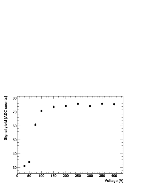
These spectra were acquired for a range of increasing voltage applied across the sensor. Figure 6 shows the most probable values of the pedestal-subtracted pulse height distributions measured as a function of the bias voltage. The maximum signal was reached, as expected, at an electric field of about 0.25 Vm-1, corresponding to a bias voltage of 125 V for a sensor with 500 m thickness. Above this voltage the signal is constant.
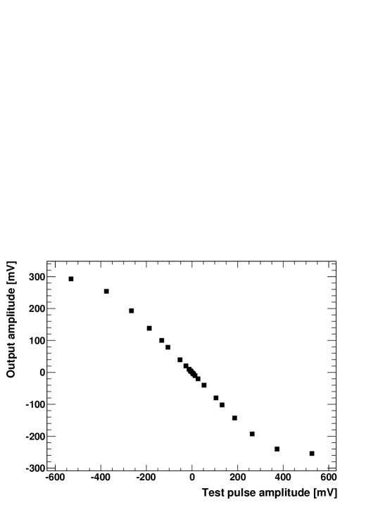
The linearity of the response of the whole readout chain was investigated using test-pulses fed in a dedicated preamplifier input. The result is shown in Figure 7. For both polarities a linear response is found up to test-pulse amplitudes corresponding to approximately 5 MIP equivalents. For test-pulse amplitudes above this value the readout becomes non-linear and approaches saturation at about 10 MIPs.
To test the proper functionality in the cooled tracker environment of CMS, the modules were operated in a climate chamber with five temperature cycles from 20 to 50 ∘C. Leakage and supply currents as well as the test-pulse response were measured and found to be in the expected range. The stored results of these measurements will be compared with measurements of the same quantities taken during operation of the modules in CMS.
7 Installation in CMS
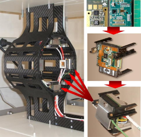
The components of the modules and the completed modules mounted on the carrier structure are shown in Figure 8. The modules contain in addition to the BCM1F components also sensors from the current monitor BCM1L. Both systems are shielded with a double-cage structure. The inner cage is connected to the ground of the back-end readout. The outer cage is connected to the carbon-fibre support222The carbon fiber support is not connected to the CMS detector ground.. The two cages are insulated from each other to mitigate frequency dependent pick-up effects on carbon fibre structures observed elsewhere [14]. The eight BCM1F modules with their corresponding infrastructure were successfully installed and tested at the beginning of August 2008.
8 First Measurements with LHC Beams
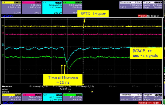
When first beam circulated in the LHC at the beginning of September 2008, the BCM1F was operational and signals from beam-halo particles were recorded. One of the first beam-generated signals from BCM1F, observed on an oscilloscope, is shown in Figure 9.
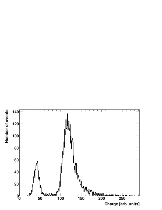
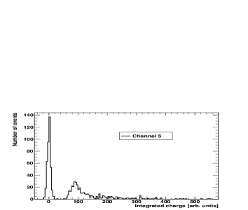
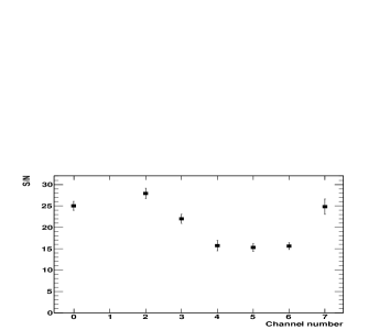
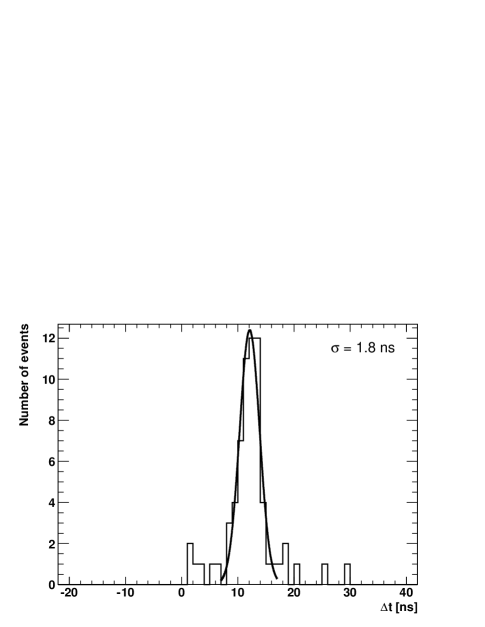
The readout of the BCM1F modules was triggered by a bunch pickup detector, BPTX [15], indicating that a proton bunch crossed the CMS detector. A time window of about 500 with respect to the trigger was recorded by the ADC. Figure 10 shows, as an example, the spectrum of signals from one of the detector modules. The signal size is obtained by integration of the signal pulse over time. The distributions for the other channels are very similar. The signal-to-noise ratios obtained from these distributions are also shown in Figure 10 for all channels333Channel one had a faulty cable at the ADC input at the time of this measurement. . The values of the signal-to-noise ratio vary between 15 and 25 and are slightly better than the ones obtained in laboratory measurements before installation. Since the LHC was filled with beam in one direction only, the beam halo particles should follow this direction. To demonstrate the capabilities of BCM1F the signal arrivals times in the flash ADC are measured with respect to the BPTX trigger signal. The distribution of the difference between arrival times of signals from sensors in different z-planes but equal azimuthal positions is shown in Figure 11.
From a Gaussian fit, a value of 12.4 is obtained for the time difference, corresponding precisely to the expected time-of-flight of a relativistic particle between the two BCM1F planes on the z and z side. The variance of the Gaussian amounts to 1.8, leading to an estimate of the single hit timing resolution of 1.3 ns.
9 Conclusions
The BCM1F is a fully functional sub-detector of the BRM system of CMS and will be vital for monitoring beam conditions close to the beam-pipe inside CMS. It comprises 8 modules each containing an sCVD diamond sensor, a front-end ASIC and an optical analog signal transmission to scalers, flash ADCs and TDCs. The system is operated independently from the other CMS sub-detectors.
System tests of each module in the laboratory show that performance matches requirements.
Samples of sCVD sensors were exposed to a high intensity proton beam up to fluences expected at the location of BCM1F for the nominal LHC running. The signal amplitude measured for MIPs is reduced to 20% of the original one, approaching a level critically low for MIP counting. Using the ADC the size of the MIP amplitude will be monitored as a function of the LHC operation time allowing us to replace the sensors if necessary.
BCM1F was successfully installed and was operational when LHC was filled with first beam. Data taken with beam show a slightely better signal-to-noise as reached in the laboratory tests. A measurement of the signal arrival times using a flash ADC indicates a promising single hit timing resolution of about 1.3. This will allow the separation of incoming halo particles correlated to a certain bunch from interaction products created at the IP.
Different readout-modes and time windows for data capture are programmable. Data can be written on a local disk and published to the CMS readout system. Local data preprocessing will deliver the shift-crew a detailed picture on the beam-halo count rates as a function of the time. Data of several orbits stored in circular memory will allow diagnostics just after a beam abort.
The BCM1F detector is ready for data taking in the commissioning phase of the LHC.
10 Acknowledgments
We thank J.P. Chatelain for his contributions to design and manufacture the mechanical structures. We would like to thank our colleagues in the BRM group for their advice and assistance. We are grateful to CMS Technical Coordination for assistance in launching and sustaining the project, particularly in its early phases. We also acknowledge the contribution of the CERN, CMS and DESY technical teams which helped bring it to a successful conclusion. We express our gratitude to PSI for allowing us to use the proton beam and in particular to K. Deiters for his collaboration there. The Rutgers University group is grateful for the support by NSF. R. Hall-Wilton is grateful for the support of the Israeli Technical Associates Program.
References
- [1] The CMS Collaboration, S. Chatrchyan et al. ,”The CMS experiment at the CERN LHC”, 2008 JINST 3S08004.
- [2] L. Evans and P. Bryant (editors), “LHC Machine”, 2008 JINST 3S08001.
- [3] L. Fernandez-Hernando et al., “Development of a CVD diamond Beam Condition Monitor for CMS at the Large Hadron Collider”, Nucl. Inst. and Meth. A552 (2005) 183, A. Macpherson, “Beam Condition Monitoring and radiation damage concerns of the experiment”, Proceedings LHC Project Workshop, Chamonix XV (2006) 198, D. Chong et al., “Validation of synthetic diamond for a Beam Condition Monitor for the Compact Muon Solenoid Experiment”, IEEE Trans. Nucl. Sci. 54 (2007) 182.
- [4] A. J. Bell on the behalf of the BRM group, “Beam and Radiation Monitoring for CMS”, 2008 IEEE Nuclear Science Symposium Conference Record, pp 2322-2325, http://ieeexplore.ieee.org.
- [5] V. Cidro et al., “The ATLAS Beam Conditions Monitor”, 2008 JINST 3P02004, The LHCb Collaboration, A. Augusto Alves Jr et al., “The LHCb Detector at the LHC”, 2008 JINST 3S08005.
- [6] P. Dong et al., “Beam Condition Monitoring With Diamonds at CDF” IEEE Trans. Nucl. Sci. 55 (2008) 328.
- [7] M. Brunisma et al., “CVD diamonds in the BaBar radiation monitoring system”, Nucl. Phys. B150 (2006) 164.
- [8] Element Six Ltd., King’s Ride Park, Ascot, Berkshire SL5 8BP, UK.
- [9] RD42 Status Report, http://cdsweb.cern.ch/record/1098155.
- [10] W. Lange et al., “INVESTIGATION OF A SINGLE CRYSTAL DIAMOND SENSOR AND ITS APPLICATION IN BACKGROUND MEASUREMENTS FOR HERA”, talk given at the NoRHDia Workshop 2006, GSI Darmstadt, http://www-norhdia.gsi.de/index.php?mgid=6#3rd.
- [11] RD-42 Collaboration, CERN, “Development of Diamond Tracking Detectors for High Luminosity Experiments at the LHC”, CERN-LHCC-2006-10 (2006), W. de Boer et al., “Radiation Hardness of Diamond and Silicon Sensors Compared”, Physica Status Solidi A204 (2007) 3004.
- [12] J. Kaplan and W. Dabrowski, “Fast CMOS Binary Front End for Silicon Strip Detectors at LHC Experiments”, IEEE Trans. Nucl. Sci. 52 (2005) 2713.
- [13] J. Troska et al., “Optical readout and control systems for the CMS Tracker”, IEEE Trans. Nucl. Sci. 50 (2003) 1067, G. Cervelli et al., “A radiation tolerant linear laser driver array for optical transmission in the LHC experiments”, Proc. 7th Workshop on Electronics for LHC Experiments, CERN/LHCC/2001-034 (2001) pp 155-159.
- [14] M. Johnson, “Grounding and Shielding Techniques for Large Scale Experiments”, Proceedings of the 8th Workshop for Electronics for the LHC (2002), B. Quinn, “Carbon Fibre Grounding Design in the D0 Run IIb Silicon Detector Design”, Nucl. Inst. and Meth. A511 (2003) 180.
- [15] C. Ohm, “Phase and Intensity Monitoring of the Particle Beams at the ATLAS Experiment”, Linköping University, The Department of Physics, Chemistry and Biology, LITH-IFM-EX-07/1808-SE (2007), C. Ohm and T. Pauly, arxiv.org/pdf/0905.3648 (2009), T. Aumeyr, “Beam Phase and Intensity Monitoring for the Compact Muon Solenoid Experiment”, Vienna University of Technology (2008).