Expressing the Behavior of Three Very Different Concurrent Systems by Using Natural Extensions of Separation Logic
Abstract
Separation Logic is a non-classical logic used to verify pointer-intensive code. In this paper, however, we show that Separation Logic, along with its natural extensions, can also be used as a specification language for concurrent-system design. To do so, we express the behavior of three very different concurrent systems: a Subway, a Stopwatch, and a Switch. The Subway is originally implemented in , the Stopwatch in , and the Switch in .
1 Introduction
Concurrent systems, specified today, can have very different properties. Depending on these properties, a practical specification language is chosen. For instance, consider a designer who can choose between the synchronous language and the guarded-command language in order to specify the modal behavior of a Stopwatch, on the one hand, and the shared-memory behavior of a Switch, on the other hand. The designer will typically choose for the Stopwatch and for the Switch and not the other way around. In other words, while it is of course theoretically possible to express modal behavior with and shared-memory behavior with , it is –in terms of practical expressiveness– not interesting to do so.
The statements in the previous paragraph are based on “common design experience”, not on a formal metric of practical expressiveness. To the best of our knowledge, such a metric is not available in the current literature111Note that the conciseness of a specification is too simplistic a metric: a lengthy specification can be preferred over a short specification if, for instance, explicitly captures a design requirement that is only implicitly present in .. In this paper we do not try to find such a metric either, for we believe it is wiser to first obtain many specifications of various systems using different specification languages and to compare them based on intuitive notions of “practical expressiveness”. Based on these informal comparisons, we can then search for a metric that is both well defined and practically relevant.
In this paper we choose the formalism of Separation Logic and its natural extensions to express the behavior of three very different systems:
-
•
A Subway system, originally specified with [8].
-
•
A Stopwatch, originally specified with [7].
-
•
A Switch, originally specified with [2].
Our specifications are based on an analogy that we make with photography, explained below. The analogy is formalized by means of Separation Logic [13, 15]. This logic, in turn, is an extension of Hoare Logic and is typically not used in the way we use it in this paper, i.e. as a specification language.
An Analogy with Photography
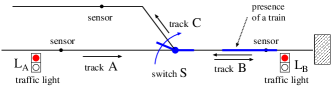
Given a concurrent system such as the Subway system in Figure 1, we make the following analogy with photography. Let various photographers be assigned to different locations in Figure 1. By taking consecutive camera snapshots, each photographer captures local change of some part of the Subway. Then, by combining all local changes, we obtain a complete specification of the Subway.
For instance, suppose photographer is assigned to take snapshots of track in Figure 1 while photographer is assigned to track . can, by taking one snapshot, either observe the presence of a train on track , denoted by , or the vacancy of track , denoted by . By taking two consecutive snapshots, can observe four possible changes: with –where we shall use to abbreviate . For example, may observe the arrival of a train on , denoted by . Likewise, may observe the continuous vacancy of track , denoted by . By combining the observations of and , we obtain the composite change , describing a system in which a train arrives on while, simultaneously, track is vacant.
The example, presented above, can be extended by adding more photographers, as we shall illustrate in Section 2 when discussing the Subway in more detail. In addition, we can generalize the notions of ‘snapshot’ and ‘change’ to the notion of ‘change of change’. This extension will be needed when specifying the modal behavior of a Stopwatch in Section 3. In terms of the analogy, the photographer capturing a scene by means of ‘change’, has become a camera man, capturing the change from one scene to another. Another generalization is needed when specifying the Switch in Section 4. There, the concept of ‘snapshot’ is generalized to that of an ‘hierarchical snapshot’, implying that each photographer can zoom in on specific details of the concurrent system under investigation. Consequently, hierarchical change is used (instead of plain change) to capture the concurrent behavior of the Switch.
Related Work
Our analogy with photography is formalized in this paper by using the following embarrassingly simple logics. First, the Logic of Snapshots is merely an instance of Separation Logic’s assertion language using the primitive of Ahmed et al. [1] instead of the usual points-to predicate [13, 15]. The key point is that formulae denote unary predicates over snapshots () of the system state. The second logic is , the Logic of Change. It is basically Yang’s “Relational Separation Logic” [16] where formulae denote binary relations of the form rather than unary predicates. For notational convenience we let refer to and to . The third logic is where formulae denote relations on relations over snapshots, i.e. sets of elements of the form: . But the semantics will require that and are always equal (or else completely irrelevant), so formulae actually denote triples of snapshots. Hence, is a straightforward adaptation of from binary to ternary relations. Continuing in the same manner, we then present , denoting elements of the form: where is equal to . Further extrapolation results in and, in general, in with and a strictly positive integer. In summary, it is more the use of the logical definitions that is new and interesting, rather than the definitions themselves.
The formalism in this paper abides by the Synchronous Hypothesis [3, 14]. To illustrate this, consider , which can be read operationally as follows: “When track ’s sensor senses the arrival of a train, the Subway system responds by turning traffic light from green () to red ().” Operationally, it makes no sense to reason in the opposite direction; i.e. by starting with the light and concluding with ’s sensor. Thus, we have an ordering from to . But, since requires that both occur simultaneously, has to be an instantaneous reaction to .
The analogy with photography, resulting in the concepts of ‘snapshot’, ‘change’, and ‘change of change’, sets it apart from other well-established formalisms, such as Statecharts [9], Communicating Sequential Processes [10], the -calculus [12], spatial logics (e.g. [4]), and process algebras [6], just to name a few. Lack of space prevents us from delving into these other formalisms here.
2 Subway
We introduce the Logic of Snapshots and its extension (i.e. the Logic of Change) to specify a Subway. The Logic of Snapshots is system dependent. That is, we shall introduce syntax for snapshots that depends on the Subway. Later, when discussing the Stopwatch (Section 3) and the Switch (Section 4), we shall introduce other syntax. , on the other hand, is only defined once.
This section consists of three parts. Section 2.1 presents the design intent of the Subway. Section 2.2 illustrates how the Logic of Snapshots and can be used to specify the Subway. Finally, Section 2.3 presents the formalization.
2.1 Design Intent
The objective in Figure 1 is to design a
Subway system so that a train can enter by track , temporarily
use track , and then leave by track [8].
At all times, at most one train is present in the Subway system. Seven
state elements constitute the system. Four state elements are inputs:
the sensor values of the tracks , , and , and the
switch . Three state elements are outputs: the actuator
of the switch and the two traffic lights and .
Each state element is presented below along with its possible values:
(i)
sensors of , , and
(ii)
Sen_, Act_
(iii)
,
When a train is on a track (e.g. track in Figure 1),
then the corresponding sensor value is , else it is . The
sensor of switch has the value when tracks
and are connected and when tracks and are
connected. The value occurs when no tracks are connected,
as is the case in Figure 1. The actuator
of switch has the value when the switch is being
steered in order to (eventually) connect tracks and . Similarly,
the value is when connecting tracks and , as illustrated
in Figure 1 by the arrowed arc. The actuator
has the value when the switch is not being steered (i.e.
typically when two tracks are connected). Traffic lights can either
be green () or red (). Green light allows a train
to enter track from the left. Green light allows a
train to depart from track by moving backwards (preferably
onto track !).
2.2 Some Specifications
We now illustrate the Logic of Snapshots and by presenting some specifications of the Subway. Since the complete formalization of the Logic of Snapshots is straightforward but lengthy, we merely illustrate it below. The more important logic , on the other hand, is illustrated below and formally defined in Section 2.3.
As a first example, consider the following snapshot specification
in the Logic of Snapshots:
(1)
It partially describes a particular instance of the Subway: track
is vacant, track is occupied, traffic light is green
() and hence granting exit to the train on track . The switch
is, based on its sensor (), connecting track with track .
The snapshot is partial because it does not capture the status of
track , the traffic light , and the actuator of the switch .
Expression (1) is a syntactic abbreviation for:
(2)
which is a tuple of four snapshot expressions. The first entry
describes the states of the tracks, the second describes the switch’s
sensor, the third describes the switch’s actuator, where abbreviates
“empty”, and the fourth describes the traffic lights. The meaning
of (2) is described next.
Let denote the set of truth
values, a set of variables, and a set of values:
and . The set of assignment
functions is . Let
denote an assignment function, i.e. . Then, the
semantical interpretation of (2), using , results in a semantic
snapshot :
(3)
(4)
(5)
iff
and
(6)
and
(7)
and
(8)
That is, each local semantic snapshot with
models the corresponding syntactic snapshot as a function. I.e.,
is a function that maps to , to , and to .
Function maps to . Function maps
to , since no information (“empty” ) is
present about the actuator . Function maps
to and to . Finally, we remark that
where is the domain of semantic snapshots.
As a second example, we illustrate the difference between Separation
Logic’s spatial conjunction and classical conjunction .
Let us take (5) and replace by , then we have:
(9)
(10)
iff
and
(11)
Now, (10) states that is a function mapping to
and and to . On the other hand, (11) states that
maps to and and to . This is
clearly not possible, so is used incorrectly in (9).
The previous example shows that can not replace without altering the intended meaning. This is due to the chosen semantics of : only describes the state of track . In the alternative classical semantics, would describe the complete state of all three tracks in the Subway system, with the additional knowledge that track is vacant222It is of course possible to avoid the use of in this paper by redefining the meaning of in accordance to the classical semantics, but the purpose of this paper is to use Separation Logic for case studies, such as the Subway system, for which it was not initially intended. . The same arguments also hold for change, such as .
For a third example, recall the photographers and from Section 1. When both photographers combine their observations, they conclude that, in accordance to a correctly-behaving Subway system, the following implication has to hold: . In words: if a train arrives on track , then, at the same time, track remains vacant. That is, it is impossible for to observe while observes, say, .
The implication
is an abbreviation for:
,
where we have ensured that the same state elements ( and )
are present on the left- and righthand side of . That
is, is defined here (by example) in terms of ,
which, in turn, is defined formally in the next section (cf. Table 1).
As a fourth and final example, consider ,
which is an abbreviation for
.
It describes the arrival of a train on while traffic light
turns from green to red. Using this, , , and the
photographer of light can combine () their observations
as follows:
(12)
From this we can, for instance, deduce that
implies .
Similar to and , the use of aids us in obtaining a short formal exposition. It could be completely avoided by only using and but at the cost of longer specifications. It too is formally defined in Table 1.
Additional Notation
Let . For
we write to denote the mapping:
and for .
Also, the domain of a partial function
is the set of ’s such that does not equal .
In particular,
. Finally, for domains and , let
denote the set . Consider functions
. We define the
operations and as follows:
if
then else
For example, if we revisit the partial function in (5).
Then where
is a function that maps to and and
to . Likewise, maps to and
and to . Clearly, and
have disjoint domains: .
2.3 Logic of Change
We are now in a position to present , the Logic of Change. After taking the following four remarks into account, Table 1 can be consulted.
First, we define semantical change as a pair of semantical snapshots:
Second, given semantical changes and , the disjointness
() and the combination () of and
can be defined:
iff
and
Third, the semantics of a formula is of the form:
or
with
where denotes the free variables in .
Fourth, an example of an expression relation is
and its valuation
amounts to checking whether holds. The trivial
definition of is omitted
from this paper.
|
|
||||||||||||||||||||||||||||||||||||||||||||||||||||||||||||||||||||||||||||||||||||||||||||||||||||||||||||||||||||||||||||||||||||||||||||||||||||||||||||||||||||||||||||||||||||||||||||||||||||||||||||||||||||||||||||||||||||||||||||||||||||||||||||||||||||||||||||||||||||||||||||||||||||||||||||||||||||||||||||||||||||||||||||||||||||
3 Stopwatch
Our second case study is a Stopwatch, introduced in Section 3.1. To capture its behavior, we shall introduce the Logic of Change of Change () and similar extensions (, , ) in Section 3.2. Finally, various specifications of the Stopwatch’s behavior are presented in Section 3.3.
3.1 Design Intent
The design intent of the Stopwatch is too lengthy to present in plain English. Therefore, we let our specifications speak for themselves. They can also be checked against the original specification, presented in [7].
The Stopwatch in Figure 2(i) can be briefly described as follows. The input signals START_STOP (or STRP for short), TICK, and RESET are immutable elements. That is, their value is completely determined by the external behavior of the Stopwatch. In fact, STRP and RESET are buttons which are pressed () or depressed () by the user, and TICK is the signal ( or ) of an external clock. The internal register COUNTER and the output signal TIME are mutable elements. That is, their value is determined by the internal behavior of Stopwatch. Finally, we also use an internal register MODE, not shown in Figure 2 to book-keep the current mode of execution. It too is a mutable element.
The locations, presented above, can be assigned to the photographers. We present six examples. First, , describing change from to , captures the behavior of a user who presses the STRP button. Second, describes a user who simultaneously presses both the STRP and RESET buttons. Third, expresses an increase of TIME from to . Fourth, expresses the sending of to TIME, followed by not sending anything to TIME (i.e. an “absent” signal). In general, is syntactically correct when . Fifth, describes a positive TICK. In general, is syntactically correct when . Sixth, expresses that the system changes from mode to mode . In general, is correct when ; its intended meaning will become clear later.
 |
3.2 Logic of Change of Change and Beyond
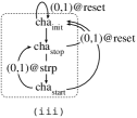
The Stopwatch is a prime example of modal behaviour: pressing a button of the Stopwatch can have a different effect, depending on the mode of operation. While the other two case studies in this paper only contain one mode of operation, the Stopwatch contains several: , , , , , We present some intuition about these modes, before defining the Logic of Change of Change (i.e. ) and its extensions. The meaning of each mode will become apparent in Section 3.3.
The modes , , and are expressed as simple formulae. Mode , on the other hand, is expressed in , describing transformations between modes , , and . That is, describes an hierarchical mode, containing the simpler modes , , and , as is illustrated graphically in Figure 2(ii). Formula is expressed in and describes transformations between formulae. That is, describes an hierarchical mode, containing simpler modes (e.g. ), as is graphically illustrated in Figure 2(iii). This hierarchical extrapolation continues with formula , describing transformations between formulae. In general, we deal with a formula with where is strictly positive.
A formula is semantically interpreted as a pair
of changes:
with:
and and
The pair , called a transformation,
denotes the change of into . The definition
of in Table 2 is self
explanatory; we stress the similarity with in Table 1.
|
|
||||||||||||||||||||||||||||||||||||||||||||||||||||||||||||||||||||||||||||||||||||||||||||||||||||||||||||||||||||||||||||||||||||||||||||||||||||||||||||||||||||||||||||||||||||||||||||||||||||||||||||||||||||||||||||||||||||||||||||||||||||||||||||||||||||||||||||||||||||||||||||||||||||||||||||||||||||||||||||||||||||||||||||||||||||||||||||||||||||||||||||||||||||
Continuing in the same manner, a formula, such as ,
is semantically interpreted as a pair of a pair of changes:
iff
and
and
where and are formulae. ’s complete
definition is obvious and omitted from this paper. The same remark
holds for (a pair of a pair of a pair of changes) or,
in general, with where is strictly
positive. The logics and are used in Section 3.3
to capture the preemption mechanisms of the Stopwatch.
Conventions
We present two conventions. First, an underscore denotes a don’t care value. E.g., abbreviates . Likewise, abbreviates .
Second, similar to Section 2.2,
the implication
abbreviates:
.
The previous remark holds for any of the logics. Consider for instance
and the following expression:
and suppose and only describe changes
of TICK, COUNTER, and TIME. Then this expression
is an abbreviation for:
3.3 Some Specifications
We start by specifying the behavior of a Basic Stopwatch, which is similar to the Stopwatch in Figure 2(i) except that the RESET button is excluded. The Basic Stopwatch’s behavior is visualized by the diagram in Figure 2(ii). The diagram distinguishes between three modes of operation: , , and . After an initialization phase, corresponding to , the system enters a loop, executing either mode or , depending on the user’s input. That is, by pressing STRP, the Basic Stopwatch transitions from mode to or vice versa. This is expressed in Figure 2(ii) by the label . On the other hand, if STRP is not pressed, the Basic Stopwatch stays in its current mode (i.e. or ).
The three modes are clarified as follows. First, mode
amounts to setting COUNTER to the value . That is:
Note also that book-keeps the current mode, which in this
case is . Second,
(1) .
The first change expresses that the value of
the COUNTER stays the same and it’s value has to be emitted
to TIME:
Since the value only has to be emitted once,
is immediately followed in (1) by , which expresses
that an absent signal is sent to TIME:
Third,
(2) .
The first conjunct expresses that, at every positive
TICK, the value of COUNTER is incremented by one (from
to ) and sent to TIME:
The second conjunct in (2) states that, in the absence of a positive
TICK, the value of COUNTER remains constant and an absent
signal is sent as output:
Having defined the formulae, we now define the
formulae of Figure 2(ii) in three steps.
First, transformation expresses the unconditional
transition from to :
That is, after the initialization phase (i.e. ) has taken
place, we automatically end up in . Second,
expresses that when pressing button STRP, a transition can
take place from to or vice versa:
with:
Third, expresses that when button STRP is
not pressed, the current mode stays the same:
with:
and where
abbreviates:
.
Finally, the complete behavior of the Basic Stopwatch is formalized
by:
Basic Stopwatch with Reset
We now enhance the behavior of the Basic Stopwatch by including the
RESET button. Every time RESET is pressed, the Stopwatch
re-initializes and starts executing from the beginning, i.e. from
. This modal behaviour is illustrated by the
diagram in Figure 2(iii) where the dotted
box is a copy of Figure 2(ii), depicting
the hierarchical mode . The preemptive transitions,
outside the box, have higher priority than the transitions inside
the box. That is, pressing RESET has higher priority than pressing
STRP. Every time RESET is pressed, the mode
is re-executed. Formally:
Findings
To conclude the Stopwatch case study, note that Separation Logic was not originally intended to express the modal behavior of a system, such as that of the Stopwatch. The above specifications seem to suggest, however, that Separation Logic may come in handy in at least two unexpected ways. First, the presented textual specifications denote the meaning of the graphical diagrams in Figure 2(ii) and (iii). These diagrams can be made (i.e. specified) by means of a graphical user interface. The corresponding graphical-specification process, in turn, could be a complementary (or competitive) alternative for the textual-based specification process. Second, since the presented logics elegantly capture modal behavior, they can of course also be used to provide an alternative formal semantics of languages such as [3].
4 Switch
Our third case study is a Switch. Its shared-memory behavior was originally333If the reader is unfamiliar with , he or she can also think of [11] as an alternative specification language for the Switch. specified in the guarded-command language [2]. In this section, however, we introduce the Logic of Hierarchical Snapshots and reuse (cf. Table 1) to specify the Switch’s behavior.
This section consists of three parts. First, we present the design intent of the Switch in Section 4.1. Second, we introduce the Logic of Hierarchical Snapshots in Section 4.2. Finally, we partially specify the Switch’s behavior in Section 4.3.
4.1 Design Intent
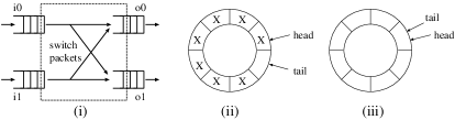
The Switch in Figure 3(i) contains two input s ( and ) and two output s ( and ). A data packet can arrive on or . If the first bit of that packet has the value , then it is routed to , else to . Each has the capacity to store data packets and management packets (see below). Each packet contains bits. A data packet can only move if the output is not full. A shared resource collision can occur when the data packets at the head of both input s have the same destination buffer (i.e. shared memory). In this case, is given priority and ’s data packet is delayed.
The three management packets (of each ) are the and pointers and the empty entry in Figure 3(ii). The pointer refers to the entry in the that contains the head data packet (if any). The pointer refers to the first empty entry. To distinguish a full from an empty (cf. Figure 3(iii)), one buffer entry is not used to store a data packet. This entry, hence, stores the third management packet of the . We also mention that the and pointers are stored in buffer entries and , respectively.
4.2 Logic of Hierarchical Snapshots
The Logic of Snapshots has the purpose to concisely describe hierarchical storage. We present examples below, omitting the obvious but lengthy formal definitions.
Suppose input buffer is assigned to photographer .
Then can zoom in on, say, entry number of
and take a snapshot of the stored packet pack. If pack
resembles the number five, then observes .
can zoom in further by taking a snapshot of, say, the first two bits
of pack. would then observe: .
The first conjunct expresses that the very first bit (index )
has the value one. The second conjunct states that the second bit
(index ) has the value zero. This indeed corresponds to the bit
notation of the number , which is with the least
significant bit (index ) being the rightmost bit. If
chooses to observe consecutive bits of pack, starting
from bit index , then we may write because
these ten bits, , resemble the number two. The general
notation is: with , and where
is the corresponding value. Finally, note that can also
combine disjoint snapshots of as for example:
.
The Semantics of Hierarchical Snapshots
, the domain of semantic snapshots for the
Switch, is defined in terms of , a parameterized semantic algebra:
The first parameter refers to the buffers in Figure 3(i).
Each buffer contains entries of bits each.
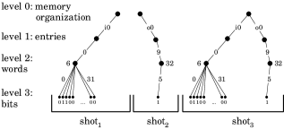
Instead of giving a lengthy definition of , we illustrate three semantic snapshots in Figure 4. For example, is the semantic snapshot that models the syntactic snapshot .
Some more concepts follow. A path is a concatenation of edge numbers,
such as . The trace of a tree is the set of paths
that characterize all the level 3 nodes (i.e. bits) of . E.g.:
Two trees are disjoint () iff their traces are disjoint:
iff
Thus, holds. Since and
are disjoint, they can be combined () into
as follows:
with
Indeed, in Figure 4 represents the
combination of and . It captures the contents
of entry number of buffer and bit number of entry
number of buffer . Finally, when two non disjoint trees
are combined, then is returned. E.g.:
.
4.3 Some Specifications
In conformance to the hierarchical snapshots, presented in the previous section, we now present specifications of the Switch.
As a first example, we want
to state that no packet is taken out of input buffer –where
is or . In accordance to Figure 3(ii-iii),
we therefore want to specify that ’s head pointer
does not change. Since is stored in ,
we write the following where is or :
(i)
As a second example, we want ,
with equal to or , to state that: value
corresponds to where is
the head pointer of . That is, we want to retrieve (but not
extract) the bits, starting from index ,
from the head data packet in . Formally, we have:
(ii)
(iii)
(iv)
Note that (iii) does not specify the new contents of
and (iv) does not specify the new contents of .
Based on (ii), we can now define the following:
(v)
where is or . That is, represents the
complete data packet that is stored at the head of .
As a third example, we want ,
with equal to or , to be similar to ,
except that we now not only retrieve but also extract the data bits
from the head packet in . Formally:
(vi)
(vii)
(viii)
Note that in (vii) we now do specify the new contents of .
Based on (vi), we can define the following where is
or :
(ix)
An additional remark is that, constraints, such as:
(x)
also have to be specified. In words, (x) states that extracting a
packet from buffer implies that is not empty.
The trivial definition of is omitted.
As a fourth example, consider:
(xi)
It states that ’s head packet is extracted from the buffer
and that it’s first bit has the value . Similarly:
(xii)
The definition of is omitted from this paper.
Based on the above, we now define:
(xiii)
This expresses, amongst other things, that the departed packet
and the arrived packet are one and the same packet . Finally,
consider:
(xiv)
The arrival of a packet at implies its departure from
or . Continuing in this manner, we can completely capture
the Switch’s behavior.
Findings
To conclude the Switch case study, note that Separation Logic is typically used to verify pointer-intensive code [13, 15]. Since the Switch also contains pointers, it is less surprising, compared to the Stopwatch case study, that Separation Logic can be used as a specification language for shared-memory systems such as the Switch.
5 Conclusions & Future Work
We have captured the concurrent behavior of three very different systems by means of Separation Logic and its natural extensions. Instead of specifying a modal-based system in and a shared-memory system in , we are now able to specify both systems by means of the same formalism –not to mention the Subway system which was originally specified in . That is, we have a unifying framework for multiple design approaches that initially seemed disparate. Alternatively, we could (in future work) provide a semantics for , , and in our unifying formalism.
Critics may remark that any other specification language, say , can also be used to capture the behavior of any of the three presented systems. Hence, they might question the relevance of the formalism, presented in this paper. We respond in the two following ways.
First, we have provided insight into how three seemingly independent concurrent systems are related to each other: (i) the Switch’s behavior merely differs from the Subway’s behavior in that it requires hierarchical snapshots instead of plain snapshots, and (ii) the Stopwatch’s behavior merely differs from the Subway’s in that it requires change of change (and change of change of change) to be specified instead of only change. Now, in our formalism, anything that can be expressed with plain snapshots can also be expressed with hierarchical snapshots. Similarly, anything that can be expressed with change (cf. ) can also be expressed with the more powerful concept of change of change (cf. ), etc. So, all three concurrent systems, presented in this paper, can be expressed in one and the same formalism which we denote here (for the first time) by: , which is an instantiation of . The parameters and denote the number of changes and the hierarchical depth, respectively. For example, for the Subway, and for the Basic Stopwatch with Reset, and and for the Switch.
The potential power of our formalism lies in being able to select a specific subset, defined by the values of and , for a given application domain.
Second, we invite the reader to check whether the other specification languages (e.g. ) can in fact capture the behavior of all three concurrent systems in a uniform and sufficiently concise way. As mentioned in the introduction, practitioners will typically not use to specify a shared-memory system and will not use to specify the modal behavior of e.g. a Stopwatch.
Finally, in line with this paper, we also refer to our complementary work [5] in which we have applied different specification languages (including ) to one and the same case study (i.e. the Switch case study).
Acknowledgement
This work was partially supported by an AFOSR grant and NSF grant CCF-0702316.
References
- [1] A. Ahmed, L. Jia, D. Walker, “Reasoning about Hierarchical Storage”, LICS’03.
- [2] ”Automatic Generation of Control Logic with Bluespec SystemVerilog”, Feb. 2005 Bluespec, Inc., Available at: bluespec.com/products/Papers.htm
- [3] G. Berry, G. Gonthier, “The Synchronous Programming Language: Design, Semantics, Implementation”, Science of Computer Programming, 1992.
- [4] L. Caires, L. Cardelli, “A Spatial Logic for Concurrency”, TACS 2001, pp. 1-37.
- [5] E.G. Daylight, S.K. Shukla, “On the Difficulties of Concurrent-System Design, Illustrated with a 2x2 Switch Case Study”, accepted for Formal Methods 2009, Eindhoven, the Netherlands, November 2-6, 2009.
- [6] W.J. Fokkink, “Introduction to Process Algebra”, Texts in Theoretical Computer Science, Springer, 2000.
- [7] N. Halbwachs, “Synchronous Programming of Reactive Systems”, Kluwer’93.
- [8] N. Halbwachs, F. Lagnier, C. Ratel, “Programming and verifying real-time systems by means of the synchronous data-flow language ”, IEEE Transactions on Software Engineering’92.
- [9] D. Harel, ”Statecharts: A Visual Formalism for Complex Systems”, Science of Computer Programming, 1987, 8, pp. 231-274.
- [10] C.A.R. Hoare, “Comm. Seq. Processes”, Comm. ACM 21, 1978, pp. 666-677.
- [11] L. Lamport, “Specifying Systems: The Language and Tools for Hardware and Software Engineers”, Addison-Wesley Professional, 2002.
- [12] R. Milner, “Communicating and Mobile Systems: the -calculus”, Cambridge University Press, 1999.
- [13] P.W. O’Hearn, J.C. Reynolds, H. Yang, “Local Reasoning about Programs that Alter Data Structures”, CSL’01.
- [14] D. Potop-Butucaru, R. de Simone, J-P. Talpin, “The Synchronous Hypothesis and Synchronous Languages”, in R. Zurawski, ed., “The Embedded Systems Handbook”, CRC Press, 2005.
- [15] J.C. Reynolds, “Separation Logic: A Logic for Shared Mutable Data Structures.”, LICS’02.
- [16] H. Yang, “Relational Separation Logic”, Theoretical Computer Science, Vol. 375, Issue 1-3, May 2007, pp. 308-334.