Superconducting RF cavity R&D for future accelerators
Abstract
High-beta superconducting radiofrequency (SRF) elliptical cavities are being developed for several accelerator projects including Project X, the European XFEL, and the International Linear Collider (ILC). Fermilab has recently established an extensive infrastructure for SRF cavity R&D for future accelerators, including cavity surface processing and testing and cavity assembly into cryomodules. Some highlights of the global effort in SRF R&D toward improving cavity performance, and Fermilab SRF cavity R&D in the context of global projects are reviewed.
I Introduction
Substantial effort is being expended in the quest for high gradients in superconducting radiofrequency (SRF) cavities for ongoing and proposed projects: (1) the test/user facilities STF (KEK), NML (Fermilab), and FLASH (DESY), (2) the European XFEL currently under construction, (3) Project X at Fermilab, and (4) the International Linear Collider (ILC). The common requirements or choices for the high-gradient cavities in these projects are gradients of at least 23 MV/m, =1, elliptical shape and an accelerating mode frequency of 1.3 GHz. Recent SRF R&D highlights in the pursuit of high cavity gradients and the status of Fermilab SRF infrastructure development are reviewed.
II Achieving High Gradient
Achieving high gradient in SRF cavities for current projects requires pure niobium, an excellent surface quality, and a good geometry.
For the ILC ilc_rdr , the niobium sheets from which cavities are formed must have a residual resistivity ratio (RRR) of at least 300, consistent with very high purity niobium, to ensure good superconducting properties.
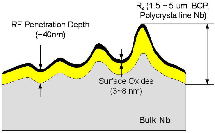
Because RF fields occupy the first 40 nm of the inner cavity surface for these cavities, as shown in Fig. 1, the quality of the innermost surface is critical and must be carefully controlled both during cavity fabrication and test preparation. To avoid the inclusion of contaminants or defects apparent after the sheet manufacturing, eddy current scanning (ECS) of all sheets is performed before cavity fabrication. ECS has proven to be a very useful feedback mechanism for material vendors, constributing substantially to an overall material quality improvement in recent years. After fabrication, the cavity inner surface must be very smooth, with no inclusion of foreign particles, or topological defects such as bumps or pits or sharp niobium grain boundaries, which could increase surface resistance locally. In addition to the strict quality assurance for the material, the introduction of dust or other microscopic contaminants must be avoided after the final surface preparation, to prevent field emission which can become dark current during machine operation and cause undesirable heating in superconducting elements and damage to accelerator components.
In selecting a cavity geometry for optimum performance, cavity cell shapes are typically optimized for low peak surface magnetic field (Hpeak) and low peak surface electric field (Epeak) relative to the gradient (Eacc), as well as ease of surface processing and fabrication.
Many cavities have reached 35 MV/m or more in the last decade SRF2007_Saito ; MAC2007_Lilje , particularly single-cell cavities of varying elliptical shapes and 9-cell Tesla-shape cavities, as shown in Fig. 2.
III Surface Processing
The surface treatment intended to maximize cavity performance, developed for the ILC TTC_surfaceprep , includes initial preparation steps to remove m from the inner surface using electropolishing (EP). This initial removal step may be performed with centrifugal barrel polishing (CBP) or buffered chemical polishing (BCP) at some labs; however, the maximum gradients reached with BCP as the initial preparation step are lower than those achieved using the other methods. Cavities then undergo an 800 C annealing step, to drive hydrogen from the surface. The final preparation steps include degreasing with detergent, another light electropolishing (m), a high pressure rinse (HPR) with ultrapure water, drying in a class-10 cleanroom, and then evacuation and low-temperature baking (120 C) for about 48 hours after the final assembly with couplers. Additional surface treatments to address field emission, which occur after the final EP, will be described later. The primary methods for material removal during surface preparation are CBP, EP and BCP.
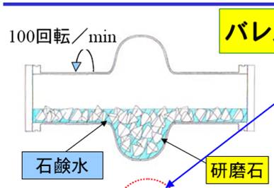
CBP is a standard technique developed for cavities at KEK in which abrasive small stones are placed into a cavity with water to form a slurry and the cavity is rotated. The KEK CBP machine and a diagram showing the CBP process are shown in Fig. 3. As a centrifugal process, material is preferentially removed from the equator region. Since standard cavities have an equator weld, CBP is very effective in smoothing the weld.
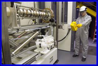
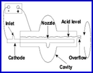
EP is an electrolytic current-supported material removal, and has been developed for use on cavities by KEK in collaboration with industrial partners, and adopted at most labs. The EP process is complementary to CBP because the material removal is preferentially on the iris. The ANL EP machine and a diagram showing the EP process are shown in Fig. 4. In this case, the niobium cavity functions as an anode, and an aluminum cathode is inserted on the cavity axis. The electrolyte is HF(40%):H2SO4 in a ratio of 1:9 by volume. Some sulfur remains on the surface after EP and will cause field emission unless it is removed.
BCP involves filling a cavity with a combination of HF(40%):HNO3(65%):H3PO4(85%) in a 1:1:2 ratio by volume. BCP has been shown to cause hydrogen contamination at the surface; this problem can be mitigated by using the appropriate proportion of acid and buffer and by keeping the temperature below about 15 C. BCP is rather less expensive than EP and is often sufficient to produce cavities attaining gradients as high as about 25 MV/m. However, it tends to enhance grain boundaries which may degrade the performance of standard fine-grain cavities.
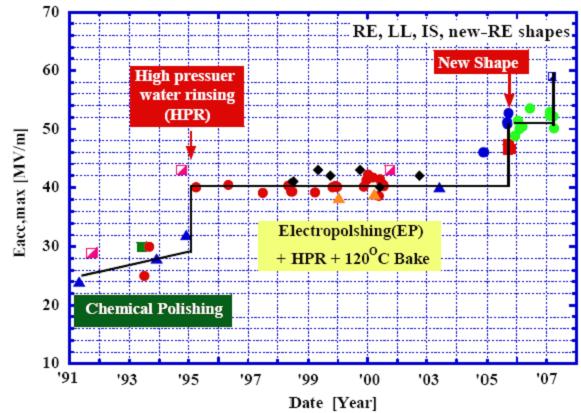
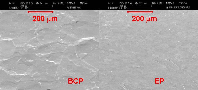
An improvement to the average maximum gradient was seen after the previous BCP standard was replaced with EP, as shown in Fig. 2. The comparison of best test results of DESY cavities treated with BCP and EP is shown in Fig. 5, revealing that the maximum gradient achieved with BCP is 25-30 MV/m, whereas the maximum gradient achieved with EP is rather higher at 35-40 MV/m. A comparison of the resulting surface smoothness is shown in Fig. 6. Although it is possible now to achieve gradients in 9-cell cavities higher than 35 MV/m, there are several factors which limit cavity performance.
IV Reducing Field Emission
One of the factors which limits cavity performance is the presence of field emission. Four recent field emission studies have been performed: flash EP (also known as fresh EP), dry ice cleaning, degreasing, and ethanol rinsing. In tests at KEK using six single-cell Ichiro-shape cavities, a 3 m EP using fresh acid after the final EP was studied flashEP . A gradient improvement to both average and rms was observed. Furthermore, the treatment was found to increase the gradient at which field emission turns on. Dry ice cleaning is a less developed but promising alternative being developed at DESY dry_ice . It reduces or eliminates contaminating particles in several ways: they become brittle upon rapid cooling, they encounter pressure and shearing forces as CO2 crystals hit the surface, and they are rinsed due to the 500 times increased volume after sublimation. Also, LCO2 is a good solvent and detergent for hydrocarbons and silicones, etc. Dry ice cleaning is a dry process which leaves no residues, because the loosened contaminants are blown out the ends of the cavities by the positive pressure, and can be performed in a horizontal orientation. The DESY dry ice nozzle is shown in Fig. 7. Dry ice cavity cleaning might be possible after coupler installation, a procedure which risks introducing field emission. Improved field emission characteristics have been seen in single-cell cavity tests, and an extension of the system to 9-cell cavities is planned.
One of several degreasing R&D studies is that of a KEK 9-cell Ichiro-shape cavity which was processed and tested at KEK and JLab geng_detergent . In an initial test at JLab, the cavity produced substantial field emission which was observed at gradients above 15 MV/m. After the cavity was ultrasonically cleaned with a 2% Micro-90 solution and standard HPR, the field emission was substantially reduced or even eliminated.
An extensive study of ethanol rinsing after the final EP was carried out at DESY DESY_ethanol . Out of 33 cavities used in the study, 20 were treated using the standard procedure and 13 with an additional ethanol rinse after the final EP. The number of tests in which field emission was observed was substantially reduced. In addition, the maximum gradient was somewhat improved, from MV/m without ethanol to MV/m with ethanol rinse. Since field emission was found to be reduced so substantially, the ethanol rinse is now part of the standard DESY cavity treatment.
V Manufacturing and Shape Studies
The vast majority of cavities which have been processed and tested in the last decade are Tesla-shape fine-grain cavities TESLA_cavities . Some fundamental changes to the standard Tesla-shape fine-grain cavities which have been under investigation include changes to the fabrication techniques, material composition and cavity shape.
Because electron-beam welding is a substantial portion of the cavity fabrication cost, and may be a source of surface defects which cause premature quenches (described later), reducing the number of equator welds required in cavity fabrication would be advantageous. Recently, a 9-cell cavity was fabricated at DESY using a hydroforming technique Singer_hydroforming . The cavity was built from three 3-cell hydroformed units, so it had only two iris welds and two beampipe welds. The surface was treated with the standard procedure including ethanol rinse. The cavity performance was comparable to cavities built using standard techniques.
Material is wasted, and a lot of time is required, to roll sheets and stamp out the disks from which fine-grain cavities are made. In principle, it should be possible to save manufacturing costs by slicing an ingot directly into large-grain sheets. It may also be possible to achieve high gradients using BCP only, since the performance of large-grain cavities should be less sensitive to the grain boundary enhancement seen in fine-grain cavities, as long as the grain boundaries are strategically located in low surface-field regions. Recent experience at DESY with large-grain cavities shows their performance is comparable to fine-grain cavities. It is still unclear whether BCP will be sufficient or whether EP will be necessary. Many 1-cell tests have shown high gradients, in a range comparable to fine-grain cavities. Recent tests on three 9-cell large-grain cavities Singer_LG showed gradients comparable to fine-grain cavities as well. Effective large-grain ingot cutting methods are being pursued in industry. Single-crystal niobium cavities have been difficult to produce, because it is difficult to produce large diameter single-grain ingots. Six single-cell single-grain cavities of varying shape and fabrication technique were fabricated, processed and tested recently by a JLab/DESY collaboration Kneisel_singlecrystal , with performance found to be comparable to that of fine-grain cavities. Unless substantial performance improvement is seen, the difficulty of producing single-grain cavities may not justify the effort required. In both the large-grain and single-grain cases, further study of crystal orientation effects is needed. For a summary of recent large-grain and single-grain cavity work, see Ref. Kneisel_LG .
It may be possible to increase the RF breakdown magnetic field of superconducting cavities by creating a multilayer coating of alternating insulating layers and thin superconducting layers Gurevich . By using multilayers thinner than the RF penetration depth, the critical magnetic field can be increased from niobium Hc1 to one similar to high-Tc superconductors, thereby significantly improving the maximum gradient achievable. Recently, a cavity was prepared with such a composite surface and tested Proslier . A 10 nm layer of Al2O3 was chemically bonded to the niobium surface of an existing single-cell cavity using atomic layer deposition. The surface was then covered by a 3 nm layer of Nb2O5. The cavity showed promising early results, and further study is underway.
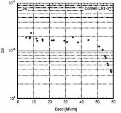
Cell accelerating length and equator diameter are fixed by and frequency respectively. However, the details of the shape may be optimized for low field emission (low Epeak/Eacc) and reduced sensitivity to the fundamental maximum surface magnetic field (low Hpeak/Eacc); see, e.g., Ref. Jacek_shapes . Excellent results on single-cell elliptical cavities have recently been obtained. A comparison of three shapes of elliptical single-cell cavities is shown in Fig. 8. A re-entrant shape cavity built and tested by Cornell University recently reached 59 MV/m Cornell_record , as shown in Fig. 9, setting a world record for the type of cavities described in this paper. Excellent results have also been achieved with an Ichiro shape cavity at KEK, with a record of 53.5 MV/m SRF2007_Saito . Furthermore, MV/m was reached on six single-cell cavities with optimized surface treatment parameters flashEP . Another low-loss shape single-cell cavity which was processed and tested by a DESY/KEK collaboration reached 47.3 MV/m Furuta_EPAC06 . It is rather more difficult to manufacture an excellent multi-cell cavity than an excellent single-cell cavity, and the very high gradients seen in single-cell alternative-shape cavities have not been achieved in 9-cell versions yet. One 9-cell Ichiro-shape cavity, without endgroups, which was processed and tested by a KEK/JLab collaboration reached up to 36 MV/m Geng_LINAC08 .

VI Understanding Cavity Behavior
Quenches and field emission appear as hot spots on the outer cavity surface. Temperature mapping (T-map) systems have been used at nearly all of the labs active in this field for many years to study these phenomena Padamsee . The existing T-map systems primarily use Allen-Bradley carbon resistors as thermal sensors, as developed at Cornell Cornell_thermometry . T-map systems commonly in use for many years at DESY include a fixed type for single-cell cavities with 768 sensors DESY_fixed_thermometry , and a rotating system for 9-cell cavities with 128 sensors DESY_rotating_thermometry . A fixed thermometry system for 9-cell cavities with four sensors around each equator and a few sensors on the endgroups has been developed at KEK and was used for tests of STF Tesla-like cavities KEK_diagnostics . Second sound detection has been used at ANL for quench location on split-ring resonators Shepard_secondsound . A selection of new hot spot detection systems are described; these systems vary in coverage, flexibility, and in the number of cavity tests required to extract useful T-map information.
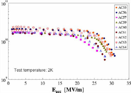
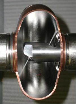
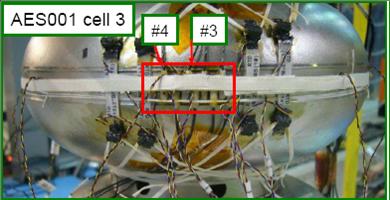
A system of Cernox temperature sensors has been developed at Fermilab fast_thermometry and used for quench location. Up to 32 sensors may be attached as needed to suspect locations; therefore the system is very flexible but also time consuming to install, typically requiring several cavity test cycles to conclusively locate quenches. It is highly portable and suitable for any cavity shape. An example installation of this system on a 9-cell cavity is shown in Fig. 10, in which a hard quench at 16 MV/m was observed, accompanied by a temperature rise of about 100 mK, above the 2K operation, over about 2 sec in sensors #3 and #4 before the quench. The quench was seen on all sensors.
New multi-cell T-map systems have also been developed. A new 2-cell system at JLab was recently commissioned JLab_2-cell_thermometry , with 160 Allen-Bradley sensors installed around each of the two equators. Understanding cavity behavior requires two cooldowns: one to measure the TM010 passband modes and determine within two the limiting cells, then a second after the T-map installation to measure the temperature distribution of the limiting cell. At LANL, a new 9-cell T-map system has been developed LANL_9-cell_thermometry which employs 4608 Allen-Bradley sensors and a multiplexing scheme to map an entire 9-cell cavity in a single test yet limit the number of cables leaving the cryostat. The preliminary results are very promising. A 9-cell T-map system at Fermilab using 8640 diodes as a multiplexed thermometer array is under development diode_thermometry . All of these multi-cell T-maps are specifically designed for the Tesla cavity shape.
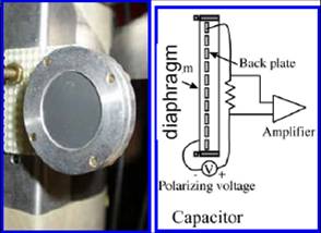
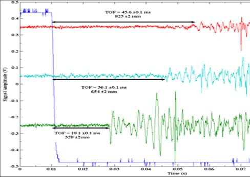
Cornell has developed a new quench location system using second sound sensors Cornell_secondsound . Second sound is a thermal wave which can propagate only in superfluid helium. It is generated when a heat pulse is transmitted from a heat source, such as a quench, through superfluid helium. In this system, eight sensors detect the arrival of the temperature oscillation, and the location is determined from the relative timing of the arrival of the oscillation from different sensors. This simple system is suitable for any cavity shape or number of cells and can locate quenches in a single cavity test. The detector is shown in Fig. 11, and an example of the data used to triangulate the location of the second sound source is shown in Fig. 12.
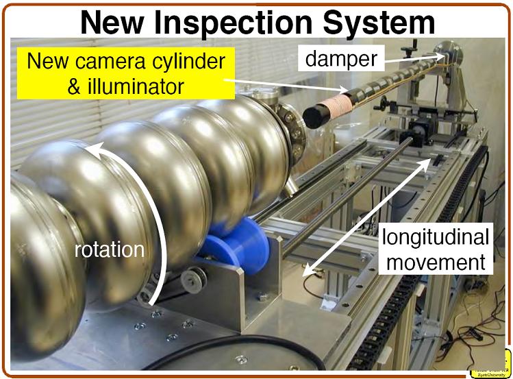
A resurgence of interest in optical inspection occurred recently when several cavities with hard quench limitation in the 15-20 MV/m range, were observed to have surface defects correlated with hot spots, using a new optical inspection system developed by Kyoto University/KEK with a clever lighting technique and excellent resolution. This optical system Kyoto_camera consists of an integrated camera, mirror, and lighting system on a fixed rod; the cavity is moved longitudinally and axially with respect to the camera system. The lighting is provided by a series of electroluminescent strips, which provide lighting with low glare on the highly polished surface. These strips can be turned off and on, and the resulting shadows studied for an effective 3D image of the depth or height of the defect. The camera resolution is about 7 m. A photograph of the Kyoto/KEK camera system is shown in Fig. 13. An optical inspection system employed regularly at JLab Geng_LINAC08 includes a Questar long-distance microscope and mirror to inspect any cavity inner surface. This system uses electroluminescent lighting. Additional optical inspection systems are in use or under development at other labs.
Because many of the cavity-limiting surface defects found by thermometry and optical inspection are located in the heat-affected zone of the electron-beam welds, weld properties are under intense scrutiny. Understanding which weld parameters might contribute to creating such defects, and ultimately eliminating the defect occurrence, is critical to improving the yield of high-gradient cavities. Note that cavities with such defects are largely, but not exclusively, from new cavity manufacturers. One group has attempted to reproduce these features on samples Cooley , to permit their systematic study. In time, study of cavity surface quality may improve cavity quality in a manner similar to the improvement seen in niobium sheet quality resulting from regular eddy current scanning.
VII Fermilab Infrastructure for SRF Development
At Fermilab, the SRF infrastructure has been substantially built up in recent years. The key program goals are the achievement of high gradients with high yields for future accelerators, the testing of cavities, and the ramp up of the production rates needed to construct cryomodules for Project X and ILC R&D. The infrastructure which has been built to achieve these goals includes facilities for single-cell cavity R&D, an ANL/FNAL joint cavity processing facility, a vertical cavity test facility, a horizontal test stand, a cryomodule assembly facility, and a cryomodule test facility.
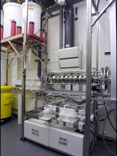
The ANL/FNAL cavity processing facility provides surface processing and assembly of cavities for vertical test, for both 1-cell and 9-cell elliptical cavities. Recent photographs of the primary facility components: EP, ultrasonic degreasing, high-pressure ultrapure water rinsing, and assembly support and vacuum leak testing, are shown in Fig. 14. All of these components are now in routine operation.
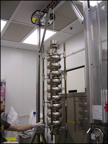
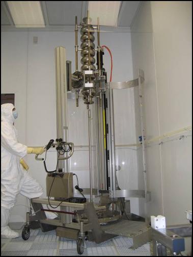
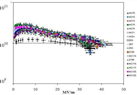
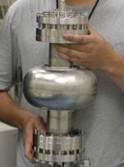
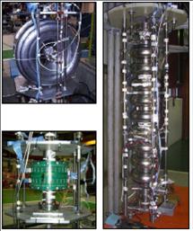
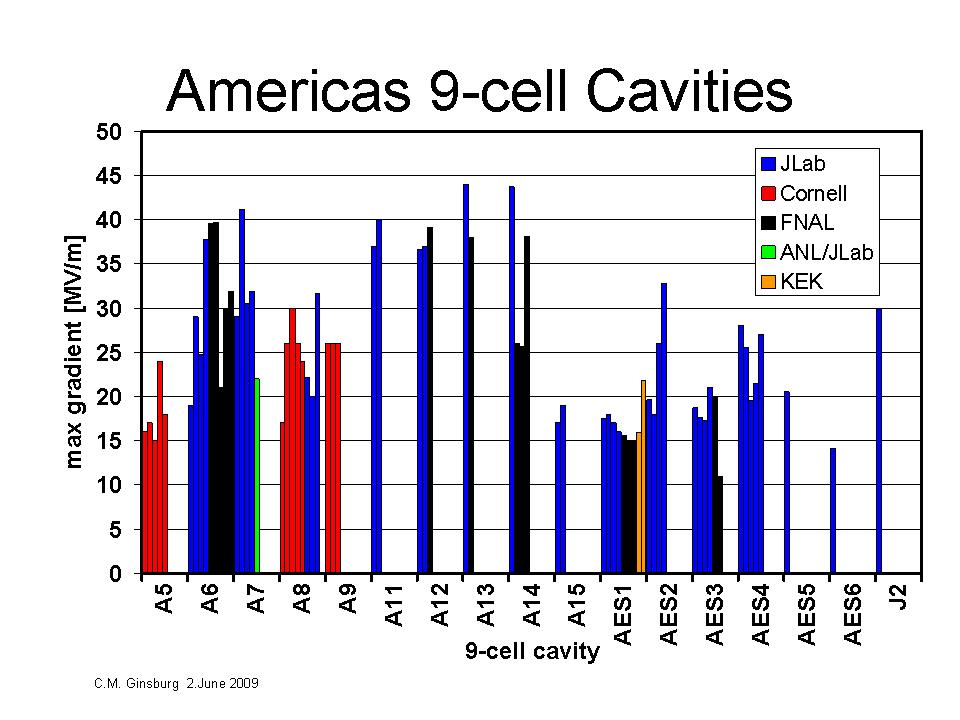
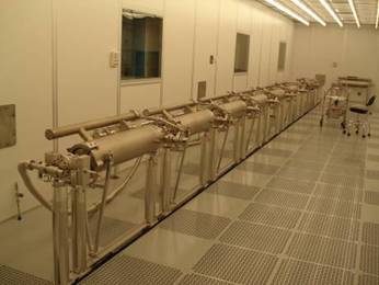
At the FNAL vertical cavity test facility (VCTF), more than 40 cavity tests have been performed in FY08/FY09, where a test is defined as a cryogenic cycle. The test cavities have been primarily 9-cell and single-cell 1.3 GHz elliptical cavities, with two 325 MHz single-spoke resonators included. The tests have primarily been for instrumentation development, e.g., variable input coupler, thermometry, cavity vacuum pumping system, and for cavity diagnostic tests for vendor development. Upgrades are planned to increase the cavity test throughput to more than 200 cavity tests per year by October 2011, to support Project X and ILC R&D. Some of the cavities recently tested at the VCTF are shown in Fig. 15. A summary of the vertical test results of 9-cell cavities is shown in Fig. 16.
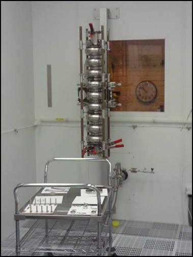
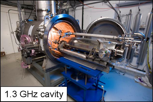
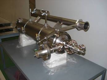
The horizontal test stand (HTS), which is used to test 9-cell cavities which have been welded into a helium tank, i.e., dressed, using pulsed high power, is now operational. It has been commissioned for both 1.3 and 3.9 GHz cavities. Four 3.9 GHz cavities were tested in 2008; they have been installed in a cryomodule which is currently at DESY. Upgrades are planned to expand the capacity with the addition of a second cryostat by 2012. A photograph of the HTS is shown in Fig. 17.
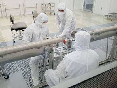
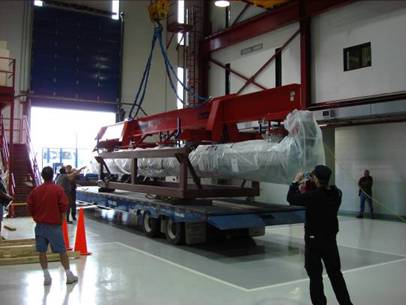
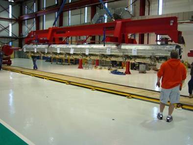
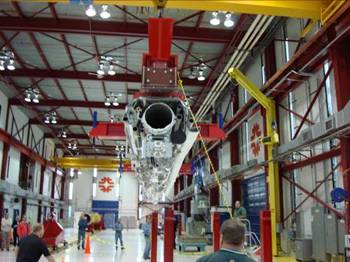
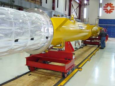
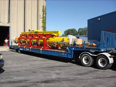
Two cryomodule assembly facilities (CAF’s) have been built at Fermilab, CAF-MP9 and CAF-ICB. The CAF-MP9 facility receives dressed cavities and their peripheral parts, and assembles these into a cavity string in a class-10 cleanroom. Then, the string assembly is installed onto the cold mass and transported to CAF-ICB. At CAF-ICB, the cavity string is aligned and assembled into the vacuum vessel. After the cryomodule is complete, it is shipped to the cryomodule test facility (NML) for testing. One cryomodule, CM1, built with cavities from DESY, has been assembled in the CAF facilities. Recent photographs of the CAF-MP9 and CAF-ICB, showing steps in the assembly of CM1, are shown in Figs. 18 and 19, respectively.
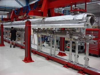
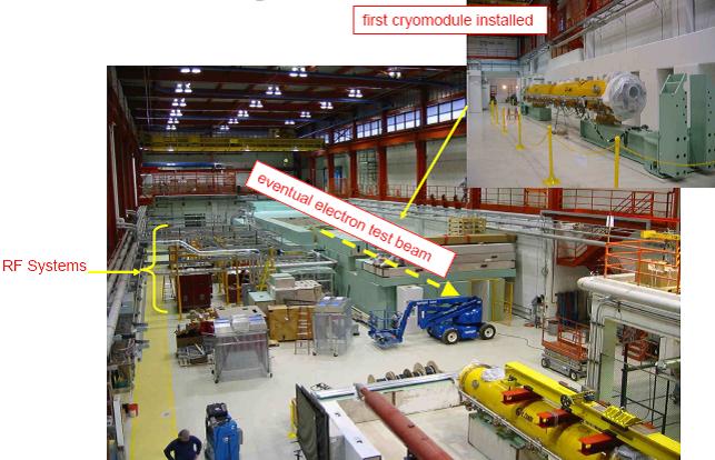
The cryomodule test facility, NML, will test one RF unit, i.e., 3 cryomodules, using a 10 MW RF system and an electron beam with ILC parameters. Various Project-X parameters will also be tested with beam in this facility. NML will provide the capability to conduct advanced accelerator R&D for future accelerator components. Through the end of FY09, the facility is being prepared to test the first Fermilab-assembled cryomodule, CM1, without beam, requiring completion of the RF system and the cryogenic system. A recent photograph of the NML facility is shown in Fig. 20.
VIII Conclusions and Outlook
Highlights of the rich R&D activity in the quest for high gradient and reduced cost have been described. Very high gradients have been measured in niobium SRF cavities: more than 50 MV/m in single-cell cavities of various shapes, and more than 35 MV/m in several 9-cell Tesla-shape cavities. Several promising new results from large-grain 9-cell cavities and hydroformed cavities address the cost and reliability issues of these cavities. Several cavities which have been limited to 15-20 MV/m by hard quench have been studied using various techniques, and the outlook is good that useful information can be fed back to cavity manufacturers to improve the yield of high-gradient cavities over time. Surface treatment is crucial for optimum performance, and several promising studies on final preparation methods have been found to sharply reduce field emission. Fundamental SRF studies are also underway, many showing promising results.
An overview of Fermilab infrastructure in pursuit of SRF R&D has been given. Among the recent accomplishments, one 1.3 GHz cryomodule using DESY dressed cavities has been built and transported to the cryomodule test facility for testing. Most key infrastructure components are now in place, with final commissioning underway.
Acknowledgements.
I am grateful to my colleagues for their contributions to the content for this talk, as referenced. I especially thank those who graciously permitted me to show their unpublished data. This manuscript has been authored by Fermi Research Alliance, LLC under Contract No. DE-AC02-07CH11359 with the U.S. Department of Energy. The United States Government retains and the publisher, by accepting the article for publication, acknowledges that the United States Government retains a nonexclusive, paid-up, irrevocable, worldwide license to publish or reproduce the published form of this manuscript, or allow others to do so, for United States Government purposes.References
- (1) International Linear Collider RDR, 2007, http://ilcdoc.linearcollider.org/record/6321/files/ ILC_RDR_Volume_3-Accelerator.pdf.
- (2) K. Saito, ”Gradient Yield Improvement Efforts for Single- and Multicells and Progress for Very High Gradient Cavities,” SRF2007, Beijing, Oct. 2007, TU202; http://cern.ch/AccelConf/srf2007/PAPERS/ TU202.pdf.
- (3) L. Lilje, ILC MAC Meeting (FNAL), April 26, 2007; http://ilcagenda.linearcollider.org/ materialDisplay.py?contribId=4&materialId=slides&confId =1388 .
- (4) G. Ciovati et al., “Final Surface Preparation for Superconducting Cavities,” TTC-Report 2008-05, http://flash.desy.de/sites/site_vuvfel/content/ e403/e1644/e2271/e2272/infoboxContent2354/ TTC-Report2008-05.pdf.
- (5) F. Furuta et al., “High Reliable Surface Treatment Recipe of High Gradient Single Cell Superconducting Cavities at KEK,” SRF 2007, Beijing, Oct. 2007, TUP10; http://cern.ch/AccelConf/srf2007/PAPERS/ TUP10.pdf.
- (6) D. Reschke et al., “Dry-Ice Cleaning: The Most Effective Cleaning Process for SRF Cavities?” SRF 2007, Beijing, Oct. 2007, TUP48; http://cern.ch/AccelConf/srf2007/PAPERS/ TUP48.pdf.
- (7) R.L. Geng, ILC SCRF Meeting at Fermilab, Apr.21-25, 2008; http://ilcagenda.linearcollider.org/getFile.py/ access?contribId=1&sessionId=5&resId=1& materialId=slides&confId=2650 .
- (8) D. Reschke and L. Lilje, ”Recent Experience with Nine-Cell Cavity Performance at DESY,” SRF 2007, Beijing, Oct. 2007, TUP77; http://cern.ch/AccelConf/srf2007/PAPERS/ TUP77.pdf.
- (9) B. Aune et al., “The superconducting TESLA cavities,” Phys. Rev. STAB 3,092001 (2000).
- (10) W. Singer et al., ”Preliminary Results from Multi-Cell Seamless Niobium Cavities,” LINAC08, Victoria, Sep. 2008, THP043; http://www.JACoW.org.
- (11) W. Singer (DESY), private communication.
- (12) P. Kneisel et al., “Performance of Single Crystal Niobium Cavities,” EPAC’08, Genoa, Jun. 2008, MOPP136; http://www.JACoW.org.
- (13) P. Kneisel, “Progress on Large Grain and Single Grain Niobium - Ingots and Sheet and Review of Progress on Large Grain and Single Grain Niobium Cavities,” SRF 2007, Beijing, Oct. 2007, TH102; http://cern.ch/AccelConf/srf2007/PAPERS/ TH102.pdf
- (14) A. Gurevich, “Enhancement of rf breakdown field of superconductors by multilayer coating,” Appl. Phys. Lett. 88, 012511 (2006).
- (15) T. Proslier et al., “Tunneling Study of SRF Cavity-Grade Niobium,” ASC08, Chicago, Aug. 2008; 2LX05, submitted to IEEE Transactions on Applied Superconductivity.
- (16) J. Sekutowicz, “New Geometries: Elliptical Cavities,” ICFA Beam Dyn. Newslett. 39, 112 (2006).
- (17) R.L. Geng et al., “High Gradient Studies for ILC with Single-Cell Re-entrant Shape and Elliptical Shape Cavities Made of Fine-grain and Large-grain Niobium,” PAC’07, Albuquerque, Jun. 2007, WEPMS006, p.2337-(2007), http://www.JACoW.org.
- (18) F. Furuta et al., ”Experimental Comparison at KEK of High Gradient Performance of Different Single Cell Superconducting Cavity Designs, EPAC’06, Edinburgh, Jun. 2006; http://www.JACoW.org.
- (19) R.L. Geng, “High Gradient SRF R&D for ILC at Jefferson Lab,” LINAC08, Victoria, Sep. 2008, THP043; http://www.JACoW.org.
- (20) H. Padamsee, J. Knoboch and T. Hays, RF Superconductivity for Accelerators, (Wiley, New York 2008), pp.164-169.
- (21) J. Knobloch, H. Muller, and H. Padamsee, “Design of a High-Speed, High-Resolution Thermometry System for 1.5-GHz Superconducting Radio-Frequency Cavities, Rev. Sci. Instrum. 65, 3521 (1994).
- (22) M. Pekeler et al., “Thermometric study of electron emission in a 1.3-GHz superconducting cavity,” SRF1995, Gif-sur-Yvette, Oct. 1995; Part. Accel. 53, 35 (1996).
- (23) Q.S Shu et al., “A novel rotating temperature and radiation mapping system in superfluid He and its successful diagnostics,” CEC/ICMC 1995, Columbus, Ohio, Jul. 1995; Adv. Cryog. Eng. 41, 895 (1996).
- (24) Y. Yamamoto et al., “Cavity Diagnostic System for the Vertical Test of the Baseline SC Cavity in KEK-STF,” SRF 2007, Beijing, Oct. 2007, WEP13; http://cern.ch/AccelConf/srf2007/PAPERS/ WEP13.pdf .
- (25) K.W. Shepard et al., IEEE Trans.Nucl.Sci.24, 1147 (1977); K.W. Shepard et al., IEEE Trans. Nucl. Sci. 30, 3339 (1983).
- (26) D. Orris et al., “Fast Thermometry for Superconducting RF Cavity Testing,” WEPMN105, PAC’07, Albuquerque, NM, USA, Jun. 2007.
- (27) G. Ciovati et al., Jefferson Lab TN-08-012.
- (28) A. Canabal et al., “Full Real-Time Temperature Mapping System for 1.3 GHz 9-cell Cavities,” EPAC’08, Genoa, June 2008, MOPP121; http://www.JACoW.org.
- (29) N. Dhanaraj et al., “Multiplexed Diode Array for Temperature Mapping of ILC 9-cell Cavities,” ASC08, Chicago, Aug.2008; 3LPB07, submitted to IEEE Transactions on Applied Superconductivity.
- (30) Z.A. Conway et al., “Oscillating Superleak Transducers for Quench Detection in Superconducting ILC Cavities Cooled with He-II,” TTC-Report 2008-06; http://flash.desy.de/reports_publications/ .
- (31) Y. Iwashita et al., “Development of high resolution camera for observations of superconducting cavities,” Phys. Rev. STAB 11, 093501 (2008).
- (32) L. Cooley, private communication.