On The Possible Mechanism Of Energy Dissipation In Shock-Wave Fronts Driven Ahead Of Coronal Mass Ejections ††thanks: Accepted for publication in Proceedings of the Solar Wind 12 Conference, Saint Malo, France, 21-26 June 2009
Abstract
Analysis of Mark 4 and LASCO C2, C3 coronagraph data shows that, at the distance R⊙ from the center of the Sun, the thickness of a CME-generated shock-wave front () may be of order of the proton mean free path. This means that the energy dissipation mechanism in the shock front at these distances is collisional. A new discontinuity (thickness ) is observed to appear in the anterior part of the front at R⊙. Within the limits of experimental error, the thickness 0.1-0.2 R⊙ does not vary with distance and is determined by the spatial resolution of the LASCO C3 instrument. At the initial stage of formation, the discontinuity on the scale of has rather small amplitude and exists simultaneously with the front having thickness . The relative amplitude of the discontinuity gradually increases with distance, and the brightness profile behind it becomes even. Such transformations may be associated with the transition from a collisional shock wave to a collisionless one.
1 Introduction
Eselevich M. and V. [2] revealed a disturbed region extending along the direction of propagation ahead of a coronal mass ejection (CME) when its velocity, , was below a certain critical velocity, , relatively to the ambient coronal plasma. Given , a shock wave with front thickness was formed in the frontal part of the disturbed region. In [3] also was shown that the coordinate system connected with the CME’s frontal structure was best suited for demonstrating differences of the disturbed region, reflecting the presence or absence of a shock wave. Moreover, the possibility of relatively accurate measurements of in the solar corona with Mark 4 and LASCO C2 was justified. Purpose of this work is to analyze a possible dissipation mechanism in the shock front, using measurements of the shock wave thickness.
2 Method of analysis
For this study, we analysed coronal images obtained by LASCO C2 and C3 onboard the SOHO spacecraft [1], presented as difference brightness , where is the undisturbed brightness at a moment , before the event considered; is the disturbed brightness at . We used calibrated LASCO images with the total brightness expressed in terms of the mean solar brightness (Pmsb).
For 1.2 R 2 R⊙, we used polarization brightness images from the ground-based coronagraph-polarimeter Mark 4 (Mauna Loa Solar Observatory, http://mlso.hao.ucar.edu). As was the case with LASCO data, these images were expressed in terms of difference brightness.
3 Identification of shock front ahead of a CME
A shock front ahead of a CME can be identified reliably only in the most simple cases. Particularly when:
-
1.
A CME has a three-part structure and consists of a frontal structure (FS), cavity, and bright core (sometimes the core can be absent).
-
2.
A CME propagates near the plane of the sky. This means that the measured CME velocity is close to the true radial velocity.
-
3.
Registration of shock wave front is implemented in the finite area in the direction of the CME motion.
In order to show that the observed discontinuity in the brightness distribution is a shock-wave front and not a current sheet ahead of, but associated with the CME, we used two different complementary approaches:
-
1.
The disturbed region state was investigated for some CMEs with different velocities, . For CMEs with velocities , a shock front was detected in the frontal part of the disturbed region ( is the critical velocity that is about the local Alfven velocity in the corona).
-
2.
The evolution process of the disturbed region and shock wave formation was studied for specified CMEs, in the coordinate system connected with the frontal structure, as the CME velocity overcomes the critical velocity [3].
Within the limits of these two approaches, eight CMEs with velocities in the range 700-2500 km s-1 were examined.
One of the most important parameters of the shock front is its thickness , since it contains information about the energy dissipation mechanism in the shock wave. Analysis in [2, 3] showed that it is possible to measure the shock front thickness correctly with Mark 4 and LASCO C2 data. Due to measurement results, an experimental dependence was constructed for eight CMEs with velocities (upper curve made-up of symbols labelled as in Figure 1). The solid thin line in Figure 1 denotes average curve for .

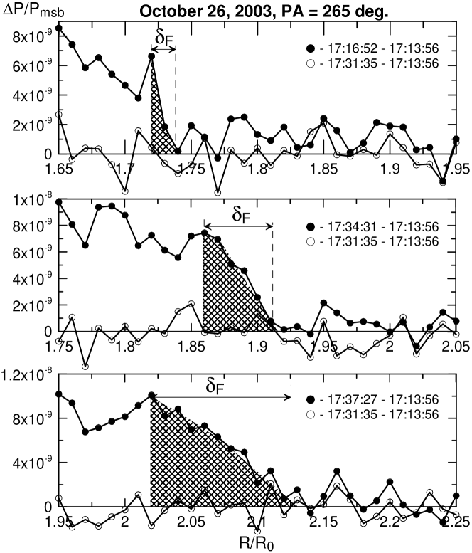
As is evident from the plot, the registered shock front thickness increases with distance. The most significant variation in is observed near the Sun. As an example, Figure 2 shows three difference brightness profiles, constructed with Mark 4 data, for the CME observed on 26 October 2003. At distances from R⊙ to R⊙, the shock front thickness increased fivefold (shock front is cross-hatched in Figure 2). (Empty circles denote difference brightness distribution before appearance of CMEs and can serve as an estimate for the noise level).
Let us compare the observed shock wave front thickness with the proton mean free path, , in the corona. The upper and lower dashed lines in Figure 1 correspond to the mean free path computed using the formula /R [6, p. 14], respectively, for temperatures K and K, and the electron density profile from [4]. The characteristic front size is comparable with the free path (), at least up to R⊙. This implies that the dissipation mechanism in the shock wave may be collisional at these distances.
Thus, we appear to encounter a rare situation where we can resolve and examine the collisional shock front structure in the plasma. This has not been possible so far, either in gas or in plasma, because of the very small size of . This may be regarded as the first experimental evidence of the theoretical conclusion that the collisional shock wave front thickness is of order of the proton mean free path [7].
4 On the possible transition from a collisional shock wave to a collisionless one
The free mean path, and, consequently, front thickness of a collisional shock wave increase away from the Sun. At a distance of more than 6 R⊙, the shock front structure must be eventually rearranged and transformed to a collisionless shock wave with the front thickness . This is evident from the fact that, in interplanetary space and at the Earth’s orbit in particular, collisionless shock waves are observed ahead of ICMEs. The possibility of such a transformation has not been studied in the past either theoretically or experimentally.
Formation of a small-scale discontinuity with thickness in the brightness distribution may be considered as a feature of a collisionless shock wave front. Let us examine the dynamics of the shock front for the CME of 20 September 1997 at distances R⊙ as an example. Figure 3 shows difference brightness distributions at successive moments of time plotted along the direction of the CME propagation (range of position angles 270-280∘. The collisional shock front is depicted by the crosshatching in plots. Its thickness increases with distance in accordance with dependence from Figure 1. Formation of a new discontinuity is observed in the anterior part of the front, from R⊙ and onward. At R⊙, the thickness of the discontinuity is R⊙ (two lower panels in Figure 3).
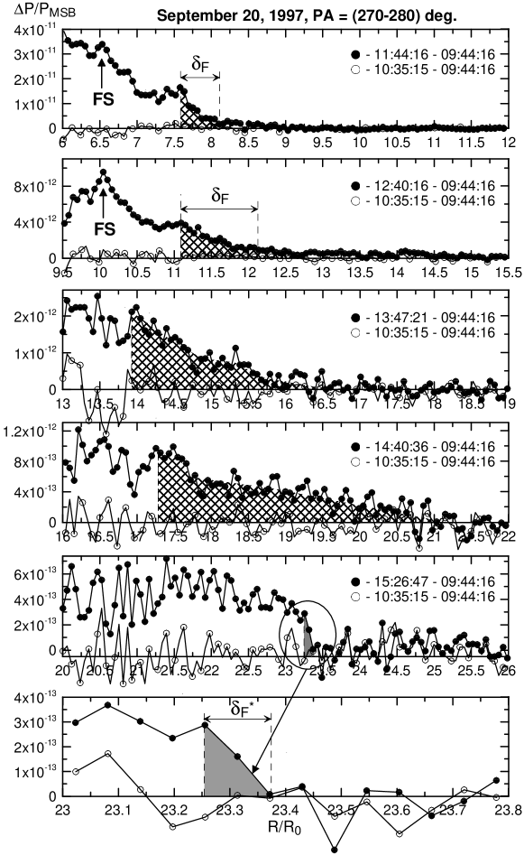
Formation of the discontinuity with thickness at 10 R R⊙ was observed for all eight CMEs used for constructing the plot of in Figure 1. Within the limits of experimental error, is about 0.1-0.2 R⊙ and is independent of distance (horizontal dash-and-dot line in Figure 1). At the initial stage of formation, the discontinuity has a rather small amplitude and exists simultaneously with the collisional front having thickness . The relative amplitude of the discontinuity gradually increases with distance, and the brightness profile behind it becomes even. Thus, transition occurs from the front with thickness to the discontinuity with thickness .
The spatial resolution of the C3 instrument is R⊙ and is approximately equal to the observed discontinuity thickness . This means that the real discontinuity scale can be much less than the thickness being observed. This, together with the fact that remains constant with distance, implies that this discontinuity is a collisionless shock wave whose observed front thickness is unresolved and determined by the spatial resolution of the C3 coronagraph. Notice that similar discontinuities in the brightness profiles were registered ahead of fast ( km s-1) halo-type CMEs at distances of more than 10 R⊙ in [5]. The authors also associated these discontinuities with collisionless shock waves.
It is notable that the thickness of the collisional shock front measured at the minimum distance R⊙ from the Sun is R⊙ (see Figures 1 and 2). This is an order of magnitude less than the thickness R⊙ of the collisionless front, determined by spatial resolution of the C3 instrument.
5 Conclusions
Mark 4 and LASCO C2, C3 coronagraph data analysis shows that, at the distance R⊙ from the Sun center along the streamer belt, the thickness of the CME-generated shock front may be of the order of the proton mean free path. This means that the energy dissipation mechanism in the shock front at these distances is collisional. A new discontinuity with thickness is observed to appear in the anterior part of the front at R⊙. Within the limits of experimental error, the thickness 0.1-0.2 R⊙ does not vary with distance and is determined by the spatial resolution of the LASCO C3 instrument. At the initial stage of formation, the discontinuity has a rather small amplitude and exists simultaneously with the front having a thickness . The relative amplitude of this discontinuity gradually increases with distance, and the brightness profile behind it becomes even. Such transformation may be associated with the transition from a collisional shock wave to a collisonless one.
Acknowledgments
The work was supported by program No. 16 part 3 of the Presidium of the Russian Academy of Sciences, program of state support for leading scientific schools NS-2258.2008.2, and the Russian Foundation for Basic Research (Project No. 09-02-00165a). The SOHO/LASCO data used here are produced by a consortium of the Naval Research Laboratory (USA), Max-Planck-Institut fuer Aeronomie (Germany), Laboratoire d’Astronomie (France), and the University of Birmingham (UK). SOHO is a project of international cooperation between ESA and NASA. The Mark 4 data are courtesy of the High Altitude Observatory/NCAR.
References
- [1] G. E. Brueckner, et al., Solar Phys. 162, 357–402 (1995).
- [2] M. Eselevich, and V. Eselevich, GRL 35, L22105 (2008).
- [3] M. Eselevich, and V. Eselevich, arXiv:0907.5245v1, (2009).
- [4] L. Strachan, R. Suleiman, A. V. Panasyuk, D. A. Biesecker, and J. L. Kohl, Astrophys. J. 571, 1008–1014, (2002).
- [5] V. Ontiveros, and A. Vourlidas, Astrophys. J. 693, 267–275, (2009).
- [6] U. Schumacher, “Basics of Plasma Physics,” in Plasma Physics, edited by A. Dinklage, T. Klinger, G. Marx, L. Schweikhard, Berlin Heidelberg, 2000.
- [7] Ya. Zel’dovich, and Yu. Raizer, Physics of Shock Waves and High-Temperature Hydrodynamic Phenomena, Academic press, New York and London, 1966.