MICE Overview
Abstract
Muon ionization cooling provides the only practical solution for preparing high brightness beams necessary for a neutrino factory or muon collider. The Muon Ionization Cooling Experiment (MICE) is under development at the Rutherford Appleton Laboratory (UK). It comprises a dedicated beam line designed to generate a range of input emittances and momenta with time-of-flight and Cherenkov detectors to select a pure muon beam. A first measurement of emittance is performed in the upstream magnetic spectrometer with a scintillating fiber tracker. A cooling cell will then follow, alternating energy loss in liquid hydrogen and acceleration by RF cavities. A second spectrometer identical to the first and another particle identification system provide a measurement of the outgoing emittance. In late 2009, it is expected that the beam and many of the particle identification detectors will be in the final commissioning phase, and the first measurement of input beam emittance will take place in 2010. The steps of commissioning, emittance measurement and cooling will be described.
I Introduction
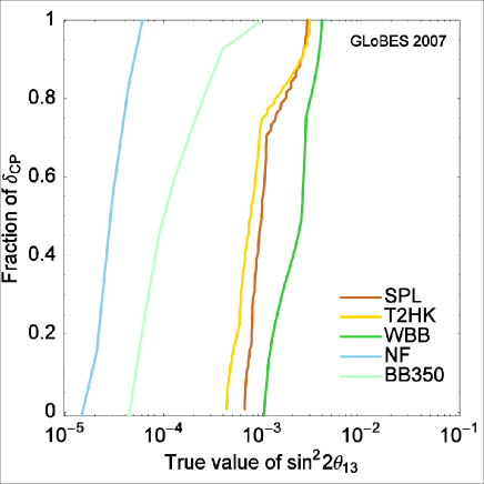
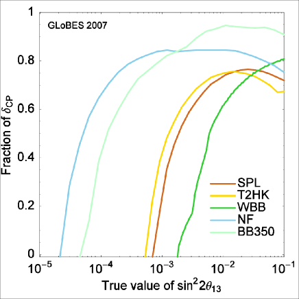
The next generation particle physics facility may be a Neutrino Factory NuFactory , to advance in-depth study of the neutrino sector, or a Muon Collider MC , for precision Higgs physics or as an energy frontier machine. Each of these facilities has been proposed to furthur the understanding of fundamental questions in particle physics. In a Neutrino Factory, the decay of stored muons () produces a well-understood, fully characterized, intense and narrow beam of muon neutrinos () and electron anti-neutrinos (). This allows the study of the Golden oscillation channel: and , where the sign of the detected muon is opposite that in the storage ring. This uniquely clean source of neutrinos can be used to study neutrino oscillations and leptonic CP violation. With muon decays per year, these key processes would enable the study of the neutrino mass hierarchy, measurement of to (see Figure 1), and would provide the best chance of discovering CP violation in the lepton sector (see Figure 2) NuFactory ; NuFact_physics1 ; NuFact_physics2 .
A Muon Collider as the next generation lepton collider () would provide a facility to perform low energy (100-1000 GeV) precision studies of the Higgs boson in the Standard Model or in possible extensions such as supersymmetry. A Muon Collider would also allow exploration of center-of-mass energies up to 4 TeV MC_physics1 ; MC_physics2 ; MC_physics3 . Because muons are much more massive than electrons, they have negligible synchrotron radiation, thus making possible a high-energy circular lepton collider with a very small footprint. In addition, collisions have much less beamstralung radiation and are therefore more monochromatic than collisions in machines. With such advantages over traditional colliders, consideration must be given to the possibility of creating a Muon Collider with guidance regarding energy scale to come from Large Hadron Collider (LHC) results.
In both the Neutrino Factory and Muon Collider, the muon beam is produced from the decay of secondary pions generated by proton collisions with a target. Due to this manner of production, the initial muon beam has a very large energy spread and large spatial dimensions. Because both of these accelerators require high brightness muon beams to reach the intended physics goals, cooling of the initial muon beam is central to the generation of the required muon intensity.
With such a short particle lifetime of 2.2 s, traditional beam cooling techniques, like stochastic cooling, cannot be used for a muon beam. Ionization cooling provides an alternative method to quickly reduce the transverse momentum spread of the beam and increase the fraction of muons fed into the acceleration portion of the Neutrino Factory or Muon Collider. In ionization cooling, the muon beam passes through liquid hydrogen (L) absorbers followed by accelerating RF cavities. The beam loses both longitudinal and transverse momentum in the absorbers, and acceleration in the RF cavities restores only the longitudinal component of the momentum. In this manner, the transverse emittance of the muon beam is reduced quickly and the beam is cooled.
MICE MICE_proposal is an experimental program whose purpose is to build, commission, and test a fully engineered section of an ionization cooling channel based on a design from the Feasibility Study-II FeasibilityII . This cooling channel will be long enough to cause a 140-240 MeV/c muon beam to undergo a 10 reduction in transverse emittance, to be measured with a precision of 1. A lead diffuser of variable thickness will be used to tune the incoming transverse beam emittance from 2 to 10 mm-rad. Particle identification detectors ensure a pure muon beam, and identical scintillating fiber spectrometers will precisely measure the beam emittance both before and after the cooling channel. MICE will provide the first demonstration of ionization cooling and will offer insight into the practical challenges involved in building a muon accelerator. MICE is an international collaboration consisting of a unique blend of more than 100 particle and accelerator physicists and engineers from the US, the UK, Switzerland, the Netherlands, Japan, Italy, China, Bulgaria, and Belgium contributing to build this unusual experiment and advance our capability to create the next generation lepton accelerator.
II MICE Overview
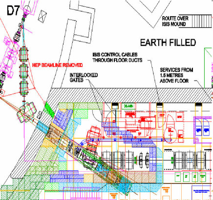
The MICE experiment is under construction at Rutherford Appleton Laboratory (RAL) on a dedicated muon beamline at the ISIS 800 MeV proton synchrotron (see Figure 3). A hollow cylindrical titanium target, designed and built by collaborators from the UK, is dipped into the proton beam at the end of the ISIS 20 ms beam cycle. Because MICE is not the sole active experiment at the accelerator, the target runs parasitically during standard ISIS user periods, dipping once every 50 ISIS cycles at a rate of 0.4 Hz.
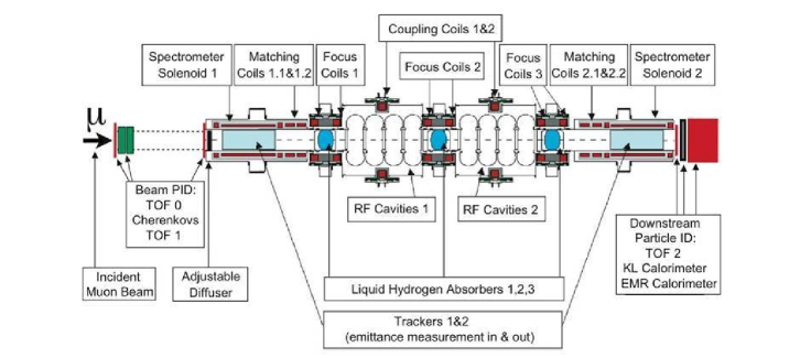
Pions from interactions in the target are captured by a quadrupole triplet within the synchrotron enclosure and then momentum-selected by the first MICE dipole magnet. Just after this dipole is a 5-m-long, 12-cm-bore, 5-T superconducting decay solenoid which contains both pions coming from the target and muons from pion decay. A second dipole magnet then selects a pure beam of muons by specifically bending particles with lower momentum than at the first dipole. The muon beam is then transported by a quadrupole triplet through particle identification detectors (PID). Two aerogel threshold Cherenkov counters (US-Belgium) and a set of time-of-flight (TOF) detectors (Italy-Bulgaria) together provide excellent / separation up to 300 MeV/c, and muon beam purity is ensured to better than 99.9. Finally, the last large acceptance quadrupole triplet transports the beam into the MICE cooling channel (see Figure 4).
At each end of the cooling channel are TOF detectors and two 1.1-m-long, 20-cm-radius scintillating fiber trackers (UK-US-Japan),each with five position measurement stations. These spectrometers are located inside 2-m-long, 4-T, uniform-field superconducting solenoid magnets (US). These complex spectrometer magnets also have four additional coils: two to match optics with the cooling channel, and two end coils to ensure field uniformity. The incoming and outgoing 6D muon beam emittances are measured by determining particle momenta and spatial coordinates with the trackers and measuring time with the TOF detectors. This time measurement will also be used to determine the phase of the electric field seen by the the muons during passage through the RF cavities.
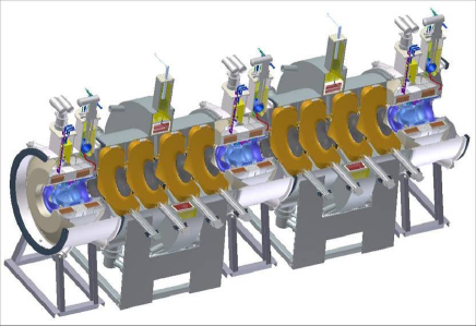
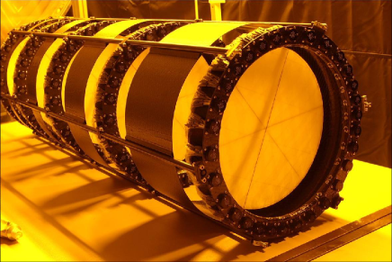
The cooling channel itself is made up of alternating low-Z liquid hydrogen absorbers and normal-conducting 201-MHz RF cavities. The absorbers are each situated within an Absorber-Focus-Coil module (AFC) consisting of superconducting coils designed to provide strong focusing at the absorbers. This focusing maximizes the effectiveness of the ionization cooling. The RF cavities must be low frequency in order to accommodate the large beam size. They are normal-conducting because they must operate within a focusing magnetic field which presents many technical challenges. The complete cooling channel is made up of two RF-Coupling-Coil (RFCC) modules and three AFC modules (see Figure 5).
In addition to the final TOF detector at the downstream end of the cooling channel, downstream PID is done with a calorimeter (Italy-Geneva-Fermilab) designed to distinguish between muons and electrons from muons that have decayed during flight through the experiment. The first part of the calorimeter is the KLOE-Like (KL) lead-scintillating-fiber sandwich layer (Italy) which degrades electrons. This will be followed by the Electron-Muon Ranger (EMR), a 1- block of extruded scintillator bars. This final detector at the downstream end of MICE is designed to measure muon momentum by range.
III MICE Status
III.1 Beamline and Target
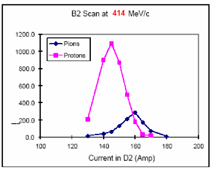
Commissioning of the MICE beamline began in fall of 2008 with data-taking to understand the conventional beamline magnet performance JSG_PAC . Protons, pions, positrons, and muons were clearly seen and magnet settings for different particle types and momenta were determined. Scans were done using the two bending magnets to maximize particle rate in scintillation counters along the beamline (see Figure 6). These early commissioning data were taken without the 5-T decay solenoid from PSI. Missing multi-layer insulation made it impossible for all coils of the magnet to become superconducting. However, in April of 2009, this problem was corrected and the magnet was successfully ramped up to its full operating current. Since then, the decay solenoid has been commissioned and is now operated routinely as part of the MICE beamline.
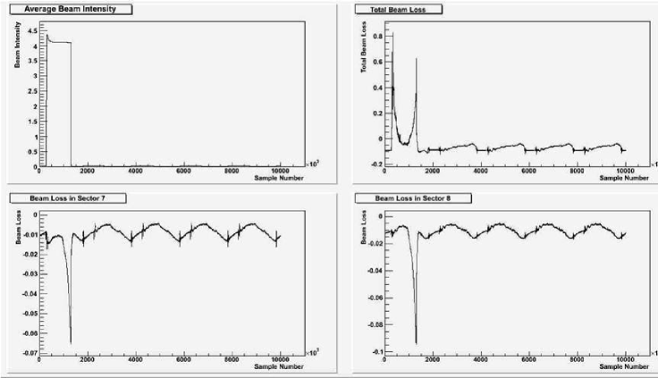
Data-taking recently resumed in September of 2009 with some dramatic changes in the MICE beam line. As previously mentioned, the 5-T decay solenoid is now operational, and has significantly increased the particle rate in MICE. Studies are currently being done to quantify the effects of the solenoid for different beamline settings. The MICE target has also been redesigned and rebuilt since a target failure was suffered in December of 2008. The original target ran for 190k dips into the ISIS beam before becoming jammed due to a problem with a loose alignment collar. In the following eight months, the target was re-engineered with a simpler hollow circular shaft, no alignment collar, and better tolerances on the bearings. The new target was installed in the ISIS beamline in August 2009 and was used in the first data-taking run of the year in September. The target has operated very well and was dipped over 60,000 times into the beam without any problems. During the September run, several studies were done to determine the optimal target operating settings. Target dip timing with respect to the ISIS cycle was varied as well as target dip depth into the beam. These parameters were modified in order to maximize particle production rate in the MICE beam line and to intersect the correct energy of particles in ISIS. Tests were also done to ensure that MICE would not adversely affect normal ISIS operations during parasitic running. To better understand the interaction between the MICE target and the ISIS beam, live beam loss information is fed into the MICE control room during running. We are able to monitor the ISIS beam intensity, the total beam loss during each cycle, and the beam loss in sectors 7 and 8 of the ISIS ring (see Figure 7). These are the areas closest to the target, and beam loss levels in these regions determine MICE running conditions. Studies are ongoing to quantify MICE particle production rates as a function of loss levels in ISIS for both positive and negative beam particles.
III.2 Particle Identification Detectors
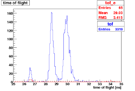
Commissioning of the first set of TOF detectors in the MICE beamline was begun in late 2008. The TOF0 and TOF1 detectors are located after the second and third set of quadrupoles, respectively, and are separated by about 10 meters. They are made up of X and Y counter arrays of inch-thick scintillator bars with dual photomultiplier (PMT) readout, with approximately 50 cm by 50 cm active area. Using a set of pion data runs, they were found to have timing resolutions of 55 to 65 ps, which was very close to design specification TOF_PAC . Figure 8 shows the time-of-flight distribution for particles in a beamline designed to select 300 MeV/c pions. Good separation can be seen between positrons, muons, and pions in this early analysis result. The third TOF detector, which will ultimately be located after the full cooling channel, has been fabricated and will be delivered to RAL for installation in the beam line in December 2009.
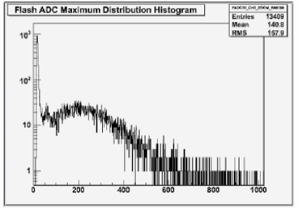
Two high density aerogel threshold Cherenkov (CKOV) detectors TOF_PAC designed to enable / separation at higher momenta, above 300 MeV/c, are located in the MICE beamline just downstream of the first TOF detector. By using the TOF system together with the threshold Cherenkov detectors, 4-5 / separation can be achieved over the full range of particle momenta expected in MICE. The two detectors have different indices of refraction with corresponding muon threshold momenta of 278 MeV/c and 220 MeV/c, respectively. The Cherenkov light from each counter is read out by four PMTs, and a typical PMT spectrum can be seen in Figure 9. Approximately 20-25 photoelectrons per counter are collected, which allows for a muon tagging efficiency of 98 over the 220-360 MeV/c momentum range of particles in MICE. Commissioning of these detectors was begun in 2008 and has continued during the latest run periods.
The KL lead-scintillating-fiber sandwich layer portion of the calorimeter system TOF_PAC is located at the far downstream end of the MICE beamline. It is designed to degrade electrons in the beam and has 4 cm active depth, corresponding to 2.5 . The KL detector was installed in the beamline, commissioned with cosmic rays, and exposed to pion and positron beams in 2008. This process continued in September 2009 with dedicated data-taking runs of 150 MeV/c and 300 MeV/c positrons and electrons focused onto the KL detector. Construction has also begun on the final calorimeter, the EMR, which is being built at the University of Geneva, and delivery of the detector is planned for July 2010.
III.3 Spectrometers
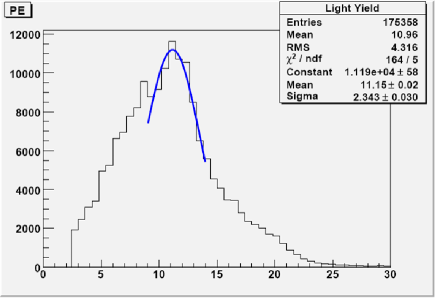
In MICE, spectrometers using particle physics techniques will measure the 10 reduction in transverse beam emittance with an absolute precision of 0.1. This will be done using two scintillating fiber tracking detectors inside solenoid magnets on each side of the cooling channel Tracker_PAC . Each detector has five measurement stations with three planes of 350 m fiber doublets rotated 120 degrees with respect to each other, thus allowing reconstruction of space points along the path of the muons. These two tracking detectors are completed (see Figure 10), and both have been tested using cosmic rays. Cosmic ray testing of the first tracker module is finished, and the detector performed as designed. Figure 11 shows the distribution of light from clusters used in tracks. This measurement was made using 175,000 hits corresponding to roughly 10,000 cosmic ray tracks. The average light yield of 11 photoelectrons met the design goal of 10.5 photoelectrons. While this is a small amount of light, the fibers are read out using Visible Light Photon Counters VLPC , solid state photo-detection devices with high quantum efficiency (QE) of 80, high gain (50,000), and low noise. Having met the design goal, we can be confident that, in spite of the very small diameter fibers chosen in order to minimize the amount of material traversed by muons, the tracker will be able to reconstruct particle tracks with high efficiency. This tracker also has fewer than 0.1 dead channels and a position resolution consistent with the design goal of 430 m.
The two 4-T spectrometer solenoids Spectrometer_PAC that will house the scintillating fiber trackers are being fabricated by Wang NMR, Inc., in conjunction with engineers from the Lawrence Berkeley National Laboratory (LBNL). Final assembly of the first spectrometer solenoid was completed, the magnet was cooled down to superconducting temperature, and training of the coils was begun. However, the magnet did not pass the acceptance tests, and modifications to the design are now being made. After the changes are made to the magnet, it will be retested and then shipped to the Fermi National Accelerator Lab (FNAL) for magnetic field measurements in late 2009. After field testing, it will be shipped to RAL where the TOF, diffuser, tracker, and magnet will be integrated and the full spectrometer unit will be installed in the MICE beam line. The second spectrometer solenoid will be delivered three months after the first.
III.4 Cooling Channel
In the cooling channel, the liquid-hydrogen absorbers reduce both transverse and longitudinal particle momentum. Hydrogen was chosen because it causes the least multiple scattering, or beam heating, for the amount of momentum absorbed compared to any other element. The first internal convection cooling absorber has been fabricated at KEK (Japan) and is undergoing thermal testing. Ten of the twenty thin aluminum windows for the absorbers have been made at the University of Mississippi. These 30-cm-diameter windows are curved for added strength and tapered to 180 m at the center to minimize muon scattering, which would counteract the desired cooling. Each of the absorbers sits inside an Absorber Focus Coil (AFC). The AFCs are being manufactured in the UK with delivery expected in 2010.
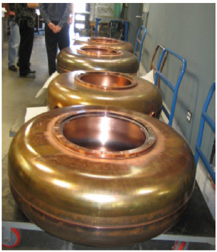
The rest of the cooling channel is made up of accelerating RF cavities. The final design review of the MICE RF Coupling Coil (RFCC) modules, consisting of four normal conducting 201-MHz cavities with a guiding magnetic field provided by a large diameter coupling coil, was finished in 2008. The coupling coils were designed by the Harbin Institute of Technology in China who are also responsible for oversight of their fabrication. This process has begun, and the prototype coupling coil will be delivered for use in the MUCOOL test area at Fermilab in late 2010, followed by the first complete MICE coupling coil delivery in summer 2011. LBNL is responsible for the fabrication of the RF cavities and integration with the RFCC modules for delivery to RAL in late 2011. The first five copper cavities are nearly complete (see Figure 12). Each cavity also requires two TiN coated beryllium windows with a specially designed curve to prevent buckling due to thermal expansion during RF heating. The first two windows have been delivered to LBNL and are undergoing quality control testing.
Once delivered to RAL and installed in the MICE beamline, each MICE cavity will require 1 MW of RF power in a 1-ms pulse at a rate of 1 Hz. This is provided by four sets of amplifiers including Burle 4616 drive amps and 2.5 MW Thales TH116 main amplifiers donated by LBNL and CERN. Significant refurbishment of the amplifiers is being done at Daresbury Laboratory (UK), where the RF power system will also be tested RF_PAC . The first 4616 amplifier has been refurbished and preliminary tests have been done. The low level RF system to drive this unit has been tested successfully against a dummy load and 2 kW of power was achieved. The first TH116 has been cleaned, repaired, the RF surfaces have been silver plated, and it is now ready for testing. A plan to test the 4616 system in steps up to 1 MW will be completed by the end of 2009.
IV MICE Schedule
MICE is proceeding in a staged manner (see Figure 13) to ensure an accurate understanding of the detectors, beamline, and measurement techniques, and to meet funding profiles. The beamline, which delivers muons to the cooling channel, and the experimental hall infrastructure for the first three steps are completed. Step I, commissioning of the beamline and PID detectors, began in 2008 and has continued during the September 2009 ISIS User Run. With a new target installed and the decay solenoid completely operational, measurement of particle production in MICE as a function of beam loss in ISIS is possible, and characterization of the muon beam will begin. Calibration of beamline simulations can be done in detail with the beamline fully operational, and optimization of magnet settings will be done. Commissioning of the TOF system, the CKOV detectors, and the KL calorimeter will also be completed in Step I, which will run through early 2010. In summer of 2010, for Step II, the first tracker and spectrometer solenoid module will be installed in the MICE beamline. When this happens, it will be possible to make the first precision measurement of the incoming MICE muon beam emittance.
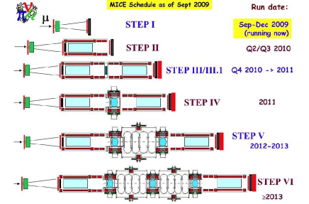
The second spectrometer solenoid will follow three months after the first, and will be installed in MICE in the summer of 2010 for the start of Step III. During this step, the muon beam emittance will be measured in both spectrometers, and the tracking detectors can be fully tested, compared, and calibrated. This comparison, without any expected change in emittance, will allow the determination of any measurement biases present and will test correction procedures. In Step III.I, a solid LiH disk will be placed between the two spectrometers, and will provide an opportunity to test muon interaction in a different absorber material. While hydrogen possesses ideal properties for cooling, the system brings with it many challenges including satisfying safety requirements, the use of very thin containment windows, and storage of the hydrogen. Because of these features, MICE has developed the capability to test other absorber materials. Another potential modification to Step III involves the addition of a plastic wedge absorber between the spectrometers to investigate emittance exchange. Step III should run by the end of 2010, and with its completion, the MICE beamline dynamics, particle production, PID systems, spectrometers, and muon beam emittance measurement techniques will be fully understood.
In Step IV, running in 2011, the first absorber-focus-coil module will be installed and will allow the first measurement of muon cooling to be made. Tests of the focusing optics will also be performed during Step IV, by exploring configurations with different magnetic-field reversals. Step V will follow in 2012 when the first RF coupling coil module is installed and MICE will perform the first test of sustainable cooling, where RF cavities restore the longitudinal momentum lost in the absorbers.
Finally, Step VI, running in 2013, will meet the primary goal of MICE by operating a complete cooling channel with three absorber modules and two RF coupling coil modules. Several configurations of the focusing optics in the central absorber will be fully tested, comparisons with Monte Carlo simulations will be made, and a detailed understanding of ionization cooling will be demonstrated. Information from the MICE studies will guide the design of future muon accelerators, provide a practical understanding of challenges presented by a realistic ionization cooling channel, and present solutions to these challenges.
Acknowledgements.
This work is supported by the U.S. National Science Foundation under grant No. PHY-0630052. The author would like to thank the UC-Riverside group and the MICE collaboration for their hard work, support, and for the opportunity to present the work being done by the collaboration.References
- (1) S. Geer, “Neutrino Beams from Muon Storage Rings: Characteristics and Physics Potential,” Phys.Rev. D57 , 6989 (1998).
- (2) V.D.Barger, “Overview of Physics at a Muon Collider,” AIP Conf. Proc. 441, 3 (1998).
- (3) A. Bandyopadhyay et al. (ISS Physics Working Group Summary Report, eds. S.F. King, K. Long, Y. Nagashima, B.L.Roberts, O.Yasuda), “Physics at a Future Neutrino Factory and Super-beam Facility,” RAL-TR-2007-19, arXiv:0710.4947v2 [hep-ph] (2007).
- (4) A.Bross, M.Ellis, S. Geer, O. Mena, and S. Pascoli, “A Neutrino Factory for both Large and Small ,” Phys.Rev. D77, 093012 (2008).
- (5) V.D. Barger, M.S. Berger, J.F. Gunion, and T. Han, “s-Channel Higgs Boson Production at a Muon-Muon Collider,” Phys.Rev.Lett.75, 1462 (1995).
- (6) V.D. Barger, “Overview of Physics at a Muon Collider,” AIP Conf. Proc. 441, 3 (1998).
- (7) M.M.Alsharo’a et al., “Recent Progress in Neutrino Factory and Muon collider Reearch within the Muon Collaboration,” Phys. Rev. ST Accel. Beams 6, 081001 (2003).
- (8) “An International Muon Ionization Cooling Experiment (MICE),” Proposal to the Rutherford Appleton Laboratory, MICE Note 021, January 10, 2003, available from http://hep04.phys.iit.edu/cooldemo/micenotes /public/pdf/MICE0021/MICE0021.pdf.
- (9) S.Ozaki, R. Palmer, M.S. Zisman, and J. Gallardo, eds., “Feasibility Study-II of a Muon-Based Neutrino Source,” BNL-52623,(June 2001).
- (10) J.S. Graulich et al., “Particle Production in the MICE Beam Line,” Particle Accelerator Conference (PAC) 2009 Proceedings, TH5RFP047, (submitted 2009).
- (11) L. Cremaldi et al., “MICE Particle Identification Systems,” Particle Accelerator Conference (PAC) 2009 Proceedings, TU6RFP047, (submitted 2009).
- (12) L. Coney et al., “The Status of the MICE Tracker System,” Particle Accelerator Conference (PAC) 2009 Proceedings, TH6REP051, (submitted 2009).
- (13) SCIFI97: Conference on Scintillating and Fiber Detectors, University of Notre Dame, November 1997, edited by A.D. Bross, R.C. Ruchti, and M.R. Wayne, World Scientific, Singapore, 1998.
- (14) S.P. Virostek et al., “Progress on the Fabrication and Testing of the MICE Spectrometer Solenoids,” Particle Accelerator Conference (PAC) 2009 Proceedings, MO6PFP070, (submitted 2009).
- (15) J. Orrett et al., “The MICE RF System,” Particle Accelerator Conference (PAC) 2009 Proceedings, TU5PFP095, (submitted 2009).