Muon Cooling and Future Muon Facilities: The Coming Decade
Abstract
Muon colliders and neutrino factories are attractive options for future facilities aimed at achieving the highest lepton-antilepton collision energies and precision measurements of parameters of the neutrino mixing matrix. The performance and cost of these depend sensitively on how well a beam of muons can be cooled. Recent progress in muon cooling design studies and prototype tests nourishes the hope that such facilities can be built in the decade to come.
I Introduction
While muon colliders have been discussed since the 1960s Tikhonin-Budker ; MC , only recently has the needed technology been understood clearly enough for a concrete plan to be developed. Muons offer important advantages over electrons. Radiative processes are substantially suppressed, allowing acceleration and collision in rings — greatly reducing the footprint and cost — as well as a more monochromatic collision energy and potential feasibility at much higher energies. A five-year plan for muon collider R&D is now available 5yp and could lead to the start of facility construction by the end of the coming decade (the 2010s).
Neutrino factories are a more recent idea Geer . Muons decaying in a storage ring constitute a unique source of well-characterized electron and muon neutrinos and antineutrinos, allowing comprehensive tests of neutrino mixing Bross ; Albright . Arguably no new technology is needed; the R&D program is focused more on issues of performance and cost than on feasibility per se NFcost . Given the decision to build one, a neutrino factory could be operational by the end of the coming decade.
| LEMC | MEMC | HEMC | ||
| 2.7 | 1.3–2 | 1 | cm2sec-1 | |
| 0.05 | 0.09 | 0.1 | ||
| Rep. rate | 65 | 40–60 | 13 | Hz |
| /bunch | 1 | 11 | 20 | |
| # bunches | 10 | 1 | 1 | |
| Storage-ring | 10 | 6 | 6 | T |
| 0.5 | 1 | 1 | cm | |
| 1 | 0.2 | 0.1 | % | |
| survival | 31 | 20 | 7 | % |
| Colliding /P.O.T. | 4.7 | 3 | 1 | % |
| 2.1 | 12 | 25 | mmmrad | |
| 0.35 | 0.14 | 0.07 | m |
| decays/year/baseline | ||
| 4 | MW | |
| Rep. rate | 50 | Hz |
| GeV | ||
| Decay-channel length | 100 | m |
| Buncher length | 50 | m |
| Phase-rotator length | 50 | m |
| Cooling-channel length | 80 | m |
| RF frequency | 201.25 | MHz |
| Absorber material | LiH | |
| Absorber thickness per cell | 1 | cm |
| Input emittance | 17 | mmrad |
| Output emittance | 7.4 | mmrad |
| Central momentum | 220 | MeV/ |
| Final muon energy | 25 | GeV |
| Number of decay rings | 2 | |
| Decay-ring circumference | 1,609 | m |
| Straight-section length | 600 | m |
The two types of facility are schematically compared in Fig. 1 and are seen to have much in common. Representative parameters are listed in Tables 1 and 2. For both types, the performance and cost depend sensitively on how well a muon beam can be cooled.
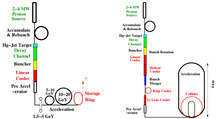
Neutrino factories might be feasible without cooling nocool , but transverse cooling of the muon beam by up to about an order of magnitude in six-dimensional (6D) beam emittance has been shown to be cost-effective. Muon colliders require much more substantial cooling — a factor 106 or so in 6D emittance — in order to achieve the 1034 luminosities required for the envisaged energy-frontier physics program. Collider designs at center-of-mass energies of 1.5, 4, 8 TeV collider-scheme and beyond King have been considered. (At the highest energies neutrino-induced off-site radiation becomes a concern; although there are strategies to mitigate this, the problem is not yet an immediate one and its solution has not been studied in detail.) Attention has also been given to less ambitious machines, e.g., a Higgs factory MC , or a Marciano or factory Eichten , which could profitably operate at lower luminosity (as well as energy), thus possibly with less cooling as well.
II Muon Cooling
The short lifetime of the muon (2.2 s at rest) vitiates all beam-cooling methods currently in use (electron, stochastic, and laser cooling). However, a method almost uniquely applicable to the muon — ionization cooling cooling — appears adequate to the challenge. In this, muons are made to pass through material of low atomic number in a suitable focusing magnetic field; the normalized transverse emittance then obeys Neuffer-Yellow
| (1) |
where is the muon velocity, the betatron function (focal length) at the absorber, the energy loss per unit length, the muon mass, and the radiation length of the absorber material. (This is the expression appropriate to the cylindrically symmetric case of solenoidal focusing, for which and cooling occurs equally in the - and - phase planes.) The first term in Eq. 1 is the cooling term, and the second is the heating term due to multiple scattering. The heating term is minimized via small (strong focusing) and large (low- absorber material). For a given cooling-channel design, equilibrium emittance is achieved when the heating and cooling terms balance.

II.1 Muon Ionization Cooling Experiment
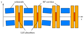
Figure 2 shows one cell of a typical ionization-cooling lattice — that of the Muon Ionization Cooling Experiment MICE (MICE) — surrounded by the input and output spectrometers and particle-identification detectors that will be used to demonstrate and characterize the ionization-cooling process experimentally at Rutherford Appleton Laboratory in the UK. MICE is designed to test transverse-emittance cooling of a low-intensity muon beam by measuring each muon individually. It will thereby demonstrate that the process is well understood in both its physics and engineering aspects, and works as simulated. The full results from MICE are expected by about 2013, with analyses of some configurations available one to two years earlier.
III 6-Dimensional Cooling
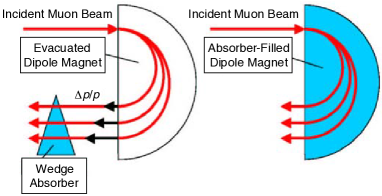
As already mentioned, a high-luminosity ( cm-2s-1) muon collider requires a more ambitious cooling scheme, reducing both transverse and longitudinal emittances by an overall factor of at least in 6D emittance. Several approaches to achieving this goal have been developed collider-scheme ; MuInc-collider by the Neutrino Factory and Muon Collider Collaboration (NFMCC) working in concert with the Fermilab Muon Collider Task Force (MCTF) and two small R&D firms with SBIR/STTR SBIR funding: Muons, Inc. MuonsInc and Particle-Beam Lasers PBL . Since ionization cooling is normally effective in only the transverse phase planes, 6D emittance reduction is typically accomplished via transverse–longitudinal emittance exchange: dispersion is used to create a correlation between path length in an energy-absorbing medium and momentum (Fig. 3), reducing beam energy spread at the expense of transverse emittance growth. Three general approaches have been shown to work in simulation: rings, helices, and snakes (Fig. 4). Like transverse cooling lattices, most 6D-cooler designs employ superconducting-solenoid focusing and benefit from the ability of such solenoids to accommodate a large aperture, generate low , and focus simultaneously in both and , enabling compactness that minimizes muon decay in flight.
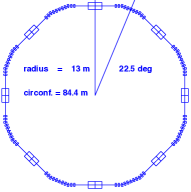
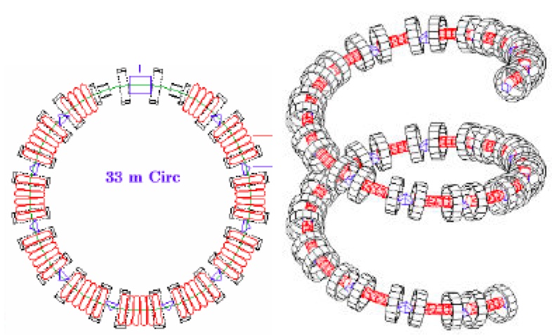
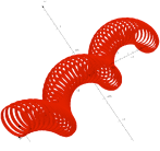
The earliest successful example of a 6D cooling channel was the 4-sided solenoid-focused ring of Balbekov tetra-ring ; Alsharoa , but it was so tightly packed as to lack space for beam injection and extraction. This first “in-principle” success led to the development of rings with space allocated for these functions Palmer-ring ; Cline-Garren , and to helices HCC ; Guggenheim , which can embody the symmetries of rings, but are open at the ends for muon ingress and egress and reduce beam loading on absorbers and RF cavities. Helices can also provide faster cooling by allowing the focusing strength to increase along the channel, decreasing the equilibrium emittance as the beam is cooled. The Helical Cooling Channel (HCC), based on a Hamiltonian theory HCC , uses a combination of “Siberian Snake” helical dipole and solenoid fields and employs a continuous, high-pressure, gaseous-hydrogen absorber so as to minimize both the deleterious effects of windows and (via pressurized RF cavities, discussed below) the length of the channel. Subsequent to the invention of the HCC, it was shown that its required solenoid, helical dipole, and (for increased acceptance) helical quadrupole field components can be produced by a simple sequence of offset current rings Kashikhin (Fig. 4, right). The “Snake” channel Alexahin (Fig. 4, far right) is the “least circular” of these approaches and brings the economy of simultaneously accommodating muons of both signs.
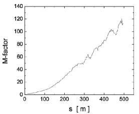
To compare a given proposed muon-cooling technique with others calls for a suitable figure of merit, and different merit factors may be appropriate depending on the details of the facility and the physics at which it is aimed. One popular merit factor is
| (2) |
where is the normalized 6D emittance and the total number of surviving muons, as a function of path-length . This peaks at 120 (Fig. 5) for the “ideal” RFOFO cooling ring of Palmer-ring (2nd from left in Fig. 4); for comparison, a similar calculation for an idealized MICE-like, linear, transverse-only cooling lattice plateaus at . These merit factors reach a plateau as the beam emittance approaches the cooling channel’s equilibrium emittance, and then fall off with increasing path-length as muon decay continues to reduce the beam intensity.
The value for the RFOFO ring is somewhat illusory as there were no windows in that simulation, nor any space left for beam injection and extraction — the gap shown at the top of the ring in Fig. 4 was filled with a 12th cooling cell. If an injection/extraction gap is made and realistic windows put in for both the LH2 absorbers and the RF cavities (see below), the merit factor falls to 15 Palmer-ring .
The schemes described above all work near the ionization minimum (). An entirely different approach seeks to exploit the much higher ionization energy-loss rate at the “Bragg peak” () PDG but has significant challenges to overcome (e.g., sufficiently rapid acceleration, and making windows thin enough to overcome multiple scattering) due to these low velocities. This “frictional cooling” regime has been studied experimentally Muhlbauer and R&D continues frictional . A recent conceptual advance, the “particle refrigerator,” seeks to increase the energy acceptance of the frictional cooling channel by two to three orders of magnitude fridge and could lead to very compact high-flux muon sources; the technique may also be applicable to decelerating and cooling other particle species besides muons other-species . In contrast to the schemes discussed previously, by taking advantage of the positive slope of the curve just below the Bragg peak, frictional cooling can cool directly in 6D, with no emittance exchange necessary.
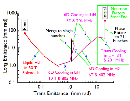
Various schemes can be evaluated and compared by displaying the “cooling trajectory” on a plot of longitudinal vs. transverse emittance. Figure 6 is an example collider-scheme in which step 2 is a simplified MICE-like transverse cooling lattice employing solid-LiH absorbers NFcost and steps 3–8 are 6D “RFOFO Guggenheim” helices Guggenheim , at the end of which the muon bunches are shorter than necessary for the luminosity goal but more transverse cooling is still needed. In principle this “final cooling” can be achieved using extremely high-field ( 50 T) solenoids enclosing LH2 absorbers, in which transverse cooling can be carried out at the expense of longitudinal emittance as the muon momentum is allowed to fall towards the Bragg peak. Although such solenoids seem feasible using high-temperature superconductor (e.g. Bi-2223 tape) operated at LHe temperature HTS-solenoid , given the large magnetic forces involved, considerable R&D will be required in order to realize them HTS-insert . (Another motivation for high-field magnets for muon colliders is that the luminosity in the collider ring increases with the frequency of collisions, with stronger dipole fields giving smaller ring circumference and more collisions per muon lifetime.) Other schemes for reaching these small transverse emittances (or yet smaller ones) have also been discussed MuInc-collider ; extreme-cool ; optical . Smaller transverse emittance can potentially give higher collider luminosity with fewer muons, thus allowing a lower-power proton driver and reducing neutrino-induced radiation as well as decay-electron background in the collider detector. The goal of a low-emittance muon collider has been substantially advanced by the recent series of workshops organized by Muons, Inc. LEMC .
Which combination of these approaches to cooling for a muon collider will in the end be chosen as optimal remains to be seen; “down-selection” among alternatives would appear to be premature at present and is one of the tasks foreseen in the 5-year plan.
III.1 6D Cooling Experiments
It is desirable to test 6D muon cooling experimentally. A proposal to do so (MANX) has been developed MANX , based on the helical cooling channel, using the MICE muon beam and detectors (or possibly a new beam that could be built at Fermilab). An important aspect of MANX is its applicability not only to muon colliders but also to upgrading the sensitivity of the proposed muon-to-electron conversion experiment at Fermilab Mu2e . Thus, it may be worth carrying out in that context, independent of the muon collider R&D plan. Other ideas have also been discussed, ranging from operation of one or more wedge absorbers in MICE (with muons selected and weighted off-line to create a suitable momentum–position correlation for emittance exchange Rogers-Snopok ; 5yp ) to constructing and testing a small-scale cooling ring Summers-ring or a portion of a Guggenheim or final-transverse-cooling lattice 5yp .
A goal of the 5-year plan 5yp is to clarify which of the various 6D cooling approaches need to be demonstrated experimentally; a proposal for a 6D demonstration experiment is one of the plan’s deliverables. Since such experiments require a substantial investment of effort and resources, only the minimum necessary number should be undertaken. If MICE with wedge-absorber tests plus 6D-cooling simulation and design studies can be shown to create sufficient confidence that 6D cooling is understood, it may even be preferable to proceed directly to a muon collider design-and-construction project, with any 6D-cooling tests done as part of that project, rather than as a separate, prerequisite effort. Both the risks and the benefits of proceeding with or without each potential experiment will need to be carefully evaluated.
IV Other R&D Issues
Although muon cooling is the least familiar aspect of muon facilities, a few other issues are also prominent in the R&D program.
IV.1 Proton Driver
These proposed facilities require intense pulses of medium-energy protons in order to make sufficient pions for the muons/year goal. A number of designs seem capable of meeting the specification ISS . Generally they entail proton-beam power in the ballpark of 4 MW — over a reasonable range in proton-beam kinetic energy (roughly 2 –20 GeV), production of pions (of the few-hundred-MeV energies which efficiently yield ionization-coolable muons) is approximately a function of beam power-on-target only Strait ; ISS .
IV.2 Targetry
Using medium-energy protons to produce so many muons requires a target system that goes well beyond the capabilities of those currently operating at the world’s accelerator laboratories Hylen . A 4 MW beam impinging on a solid target is likely to damage it substantially in a shorter-than-desirable time. Anything less than a several-month target lifetime will lead to undesirable operating overhead due to the multi-week delay involved in changing out a highly radioactive target surrounded by highly radioactive shielding.
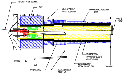
A solution to this challenge has recently been demonstrated McDonald-PAC09 in the MERIT experiment MERIT at the CERN nTOF facility. The solution is a free mercury jet flowing through vacuum within a high-field ( T) solenoid (Fig. 7). The intense proton pulse initiates a hadron shower which heats the target and disrupts it via cavitation, but the disruption occurs at a time determined by the speed of sound in mercury, long after the produced pions have escaped into the decay channel. The pulse structure of the proton beam can easily be arranged to have a sufficient gap for a new, pristine section of jet to form before the arrival of the next proton bunch. Preliminary MERIT results demonstrate power-handling capability well in excess of the 4 MW specification McDonald-PAC09 .
It has also been suggested that solid targets (now in use in high-power beams at CERN, Fermilab, ISIS, J-PARC, and PSI) may continue to be feasible up to 2–4 MW power ISS ; Hylen . For example, design studies are in progress for a graphite neutrino production target for the Fermilab NOA experiment with 2.3 MW proton-beam power Hylen .
IV.3 Rapid Muon Acceleration
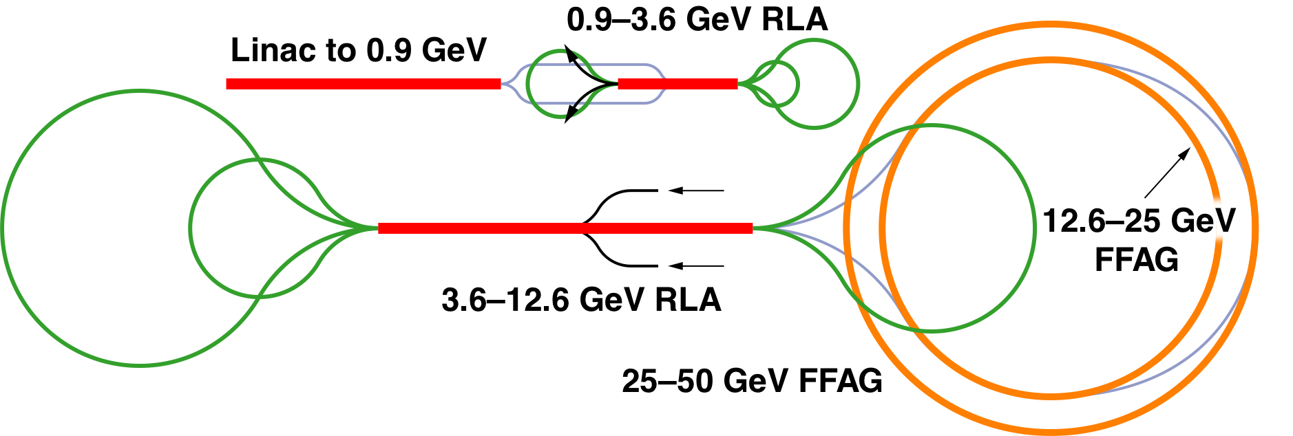
Once the muons are relativistic, time-dilation substantially suppresses decay losses. The key is then to carry out the first stages of acceleration as rapidly as possible. The proposed scheme (Fig. 8) ISS features a superconducting linac feeding a pair of “dogbone” recirculating linacs feeding a non-scaling fixed-field alternating-gradient (FFAG) accelerator, bringing the muon energy to 25 GeV. For the ultimate muon collider energies alternatives such as a very rapid-cycling synchrotron have also been considered VRCS . Clearly, simpler approaches (e.g., a single linac from ionization-cooling to final energy) are also feasible but would be considerably more costly.
The non-scaling FFAG is a recent innovation with novel beam-physics aspects including rapid resonance crossing and quasi-isochronous acceleration between RF buckets. The non-scaling feature allows small magnet apertures with concomitant cost savings. A demonstration experiment, the Electron Model with Many Applications (EMMA), is under construction at Daresbury Laboratory in the UK EMMA .
Scaling FFAGs for muon acceleration were proposed earlier nocool but featured large apertures, requiring low-gradient, low-frequency ( 10 MHz) RF cavities; this work inspired the non-scaling ideas. Recent progress on scaling FFAGs may lead to long, dispersion-suppressed straight sections compatible with higher-frequency RF Mori-Planche .
IV.4 RF Technology
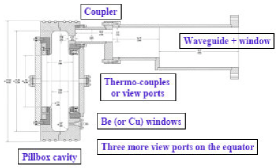
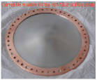
A “cost driver” for such facilities is radio-frequency (RF) acceleration. Ionization-cooling channels require operation of RF cavities in multi-tesla fields (precluding the use of superconducting cavities), which the “MuCool” R&D program has shown to be challenging Huang ; Bross . In order to accommodate the large initial beam sizes, typical cavity frequencies are in the ballpark of 200 MHz; however, much of the R&D is done on “1/4-scale” (805 MHz) prototypes. These are not only easier to fabricate, test, and modify, but are also similar to those that would be used in the later stages of the cooling system, where the beam is smaller. Cavity electrical efficiency is maximized by “pillbox” geometry, with apertures closed by thin beryllium windows (Fig. 9) — a technique usable only with muons. For a given input power or maximum surface electric field, pillbox cavities have twice the accelerating gradient of standard, open-cell cavities.
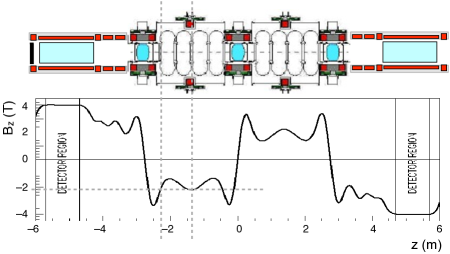
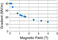
To set the scale, Fig. 10 shows that the maximum magnetic field on the RF-cavity windows in the MICE cooling lattice is about 2 T; however, in later cooling stages, where lower equilibrium emittance, and hence stronger focusing, is required, the fields will need to be many times stronger. Figure 11 shows data obtained by the MuCool R&D collaboration — a subset of the NFMCC that is developing and testing hardware components needed for muon cooling — on an 805 MHz copper cavity operated in a solenoidal magnetic field Huang . Beyond a limiting accelerating gradient, damaging sparks occur and degrade the conditioning of the cavity. The observed loss in accelerating gradient ranges from a factor of about 2 at 2 T to 3 at 4 T. This is not necessarily a “show-stopper” for muon cooling but, by requiring a stretching out of the cooling channel, could impose a significant performance loss or cost increase. Techniques are being explored to mitigate the degradation, including cavity surface coatings (e.g., via Atomic Layer Deposition ALD ), alternative cavity materials (e.g., beryllium, or beryllium-coated, cavities), open-cell cavities, and pressurized cavities. There is some indication that the degradation is related to magnetic focusing of field-emitted electrons from the window surfaces, based on early data taken with an open-cell cavity.
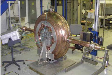
Studying the behavior of 201 MHz cavities in magnetic field is also important, as the frequency dependence of the degradation is not known. A 201 MHz cavity has been built (Fig. 12), and a large superconducting coil is under construction, with delivery anticipated in 2010. In the mean time data have been taken in the fringe field of the smaller magnet used for the 805 MHz cavity tests. At up to 0.4 T on the window nearest the magnet, a 25% degradation in maximum safe gradient is observed.
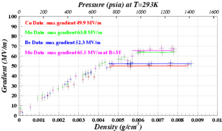
Cavities pressurized with hydrogen gas were initially proposed as a means of raising operating gradients via the Paschen effect GH2 . They were subsequently found to mitigate magnetic-field-induced gradient degradation as well (Fig. 13). Used aggressively, they enable continuous, “combined-function” cooling channels in which the ionization energy loss and re-acceleration take place simultaneously throughout the length of the channel GH2 ; HCC . A less ambitious application has also been suggested: using them in a “conventional” cooling channel (e.g., that of Figs. 2 and 10) with just enough hydrogen pressure to overcome the magnetic-field-induced degradation Zisman . In such cavities a potential pitfall is cavity loading due to acceleration of ionization electrons Alvin ; first experimental studies suggest that this can be overcome via a small (0.01%) admixture of electronegative gas Yonehara .
Rapid muon acceleration also requires high accelerating gradient, most economically achieved by means of superconducting cavities. Large, low-frequency superconducting cavities are most economically fabricated of niobium-coated copper. However, such cavities display a “Q disease”: their resonance quality factor (and hence, electrical efficiency) degrades with increasing gradient. R&D on this problem has been carried out at Cornell Cornell , with the goal of achieving 20 MV/m at 201 MHz.
V Outlook
The neutrino factory is by now well studied, with two feasibility studies FS1 ; FS2 and the International Scoping Study ISS completed and the International Design Study IDS (IDS) in progress. The IDS is aimed at completion by 2013, with production of a Reference Design Report, based on which an interested country or region could then commence a construction project. A key tactical question is the size of the neutrino mixing angle : if it is as large as a few degrees, its measurement in the Double Chooz or Daya Bay experiment could stimulate a decision to put off building a neutrino factory while multiple rounds of “superbeam” experiments are executed. Many believe, however, that the physics of neutrino mixing will ultimately demand the unique “resolving power” of the neutrino factory, and that particle physics will be better off if one is built sooner rather than later Bross .
The NFMCC/MCTF Muon Accelerator Five-Year Plan, if funded, will produce a muon collider Design and Feasibility Study Report — the first detailed feasibility study for a muon collider. This should be followed by a more detailed design study, producing a Conceptual Design Report, and a construction project, which could commence by the end of the coming decade. A key input will be the energy scale of whatever new physics is discovered at the LHC; if it is beyond the reach of the ILC, or if (for example) the data reveal a supersymmetric Higgs boson, a muon collider may suddenly become very attractive.
VI Conclusions
The long quest for high-intensity muon storage rings appears to be nearing a denouement. This should prove exciting in the coming decade, and bodes well for the future of high-energy physics!
Acknowledgements.
The author thanks his colleagues of the Neutrino Factory and Muon Collider Collaboration, the MICE Collaboration, Muons, Inc., and the Muon Collider Task Force for many enlightening conversations and interactions over many years. Work supported by DOE grant DE-FG02-01ER41159, NSF grant PHY-0758173, and DOE STTR grant (to Muons, Inc. and IIT) AC02-ER86145.References
-
(1)
F. F. Tikhonin, “On the Effects with Muon Colliding Beams,”
JINR Report P2-4120 (Dubna, 1968);
G. I. Budker, “Accelerators and Colliding Beams,” in Proc. 7th Int. Conf. (Yerevan, 1969); extract available in AIP Conf. Proc. 352, 4 (1996). -
(2)
D. V. Neuffer, R. B. Palmer, “A high-energy high-luminosity - collider,” Proc. 1994 Eur. Particle Accelerator Conf. (EPAC94), p. 52;
J. C. Gallardo et al., “Muon Muon Collider: Feasibility Study,” prepared for. 1996 DPF/DPB Summer Study on New Directions in High-Energy Physics (Snowmass96), available from http://www.cap.bnl.gov/mumu/pubs/snowmass96.html;
C. M. Ankenbrandt et al., “Status of Muon Collider Research and Development and Future Plans,” Phys. Rev. ST Accel. Beams 2, 081001 (1999);
D. Ayres et al., “Expression of Interest in R&D towards a Neutrino Factory Based on a Storage Ring and a Muon Collider,” arXiv:physics/9911009. - (3) “Muon Accelerator R&D Program: A Proposal for the Next 5 Years,” Nov. 2008, available at https:mctf.fnal.gov/annual-reports/muon-5-year-documents-r5.pdf/view.
- (4) S. Geer, “Neutrino beams from muon storage rings: Characteristics and physics potential,” Phys. Rev. D 57, 6989 (1998); ibid. 59, 039903E (1999).
- (5) A. Bross, “The Neutrino Factory – The Final Frontier in Neutrino Physics?,” FERMILAB-CONF-09-169-APC, presented at 2009 Particle Accelerator Conf. (PAC09), paper FR3RBI04.
-
(6)
A. Bandyopadhyay et al., “Physics at a future Neutrino Factory and
super-beam facility,” Rep. Prog. Phys. 72, 106201 (2009), arXiv:0802.4023 [physics.acc-ph];
M. Lindner, “The physics potential of future long baseline neutrino oscillation experiments,” in Neutrino Mass, ed. G. Altarelli, K. Winter, Springer Tracts in Modern Physics 190, 209 (2003);
M. Apollonio et al., “Oscillation Physics with a Neutrino Factory,” CERN-TH-2002-208 (Oct. 2002);
C. Albright et al., “Physics at a Neutrino Factory,” FERMILAB-FN-692 (May 2000), hep-ex/0008064. -
(7)
J. S. Berg et al., “Cost-effective design for a neutrino factory,” Phys. Rev. ST Accel. Beams 9, 011001 (2006);
D. M. Kaplan, “Recent Progress Towards a Cost-Effective Neutrino Factory Design,” 22nd Int. Symp. on Lepton-Photon Interactions at High Energy (LP 2005), Uppsala, Sweden, 30 June – 5 July 2005, arXiv:physics/0507023 (2005). - (8) C. Ankenbrandt et al., “Muon collider task force report, Fermilab-TM-2399-APC (2007).
- (9) The ISS Accelerator Working Group, “Accelerator design concept for future neutrino facilities,”JINST 4, P07001 (2009).
- (10) NuFACTJ report page: http://www-prism.kek.jp/nufactj/index.html.
- (11) R. B. Palmer et al., “A Complete Scheme of Ionization Cooling for a Muon Collider,” Proc. 2007 Particle Accelerator Conf. (PAC07), p. 3193 (2007), arXiv:0711.4275 [physics.acc-ph].
- (12) B. J. King, “Status Report on the Six-Month Study of High Energy Muon Colliders,” 18th Int. Conf. on High-Energy Accelerators (HEACC 2001), Tsukuba, Japan, 26–30 Mar. 2001, FERMILAB-MUCOOL-200, http://www-mucool.fnal.gov/mcnotes/public/pdf/muc0200/muc0200.pdf.
- (13) W. Marciano, “Muon Physics – Theory and Experimental Prospects,” presented at 11th Int. Workshop on Neutrino Factories, Superbeams and Beta Beams (NuFact09), Chicago, IL, July 20-25, 2009, available from http://nufact09.iit.edu/program.shtml.
- (14) E. Eichten, “Strengthening the Physics Case for a Muon Collider,” 2009 NFMCC Collaboration Meeting, available from http://www.cap.bnl.gov/mumu/conf/MC-090125/agenda.html.
- (15) Y. M. Ado, V. I. Balbekov, “Use of ionization friction in the storage of heavy particles,” At. Energ. 31(1) 40 (1971), English translation in Atomic Energy (Springer) 31(1) 731, http://www.springerlink.com/content/v766810126338571/.
- (16) D. Neuffer, “ Colliders,” Yellow Report CERN-99-12 (1999).
-
(17)
L. Coney, “MICE Overview,” this conference;
A. D. Bross, D. M. Kaplan, “Status of MICE,” presented at 34th Int. Conf. on High Energy Physics (ICHEP 2008), Philadelphia, PA, 30 July – 5 Aug. 2008, arXiv:0809.4795 [physics.acc-ph]. - (18) R. P. Johnson and Ya. Derbenev, “Low Emittance Muon Colliders,” in Proc. PAC07 (op. cit.), p. 706.
- (19) DOE Small Business Innovation Research/Small Business Technology Transfer (SBIR/STTR) home page: http://www.sc.doe.gov/sbir/.
- (20) Muons, Inc. home page: http://www.muonsinc.com.
- (21) Particle Beam Lasers, Inc., Northridge, CA.
- (22) V. Balbekov et al., “Muon Ring Cooler for the MUCOOL Experiment,” Proc. 2001 Particle Accelerator Conf. (PAC01), p. 3867.
- (23) M. M. Alsharo’a et al., “Recent progress in neutrino factory and muon collider research within the Muon Collaboration,” Phys. Rev. ST Accel. Beams 6, 081001 (2003).
- (24) R. B. Palmer et al., “Ionization cooling ring for muons,” Phys. Rev. ST Accel. Beams 8, 061003 (2005).
-
(25)
D. Cline et al., “Comparison of 6D Ring Cooler Schemes and Dipole Cooler for Collider Development,” Proc. PAC07 (op. cit.), p. 3038;
H. Kirk et al., “Muon Storage Rings for 6D Phase-Space Cooling,” Proc. 2003 Particle Accelerator Conf. (PAC03), p. 2008. - (26) Ya. Derbenev, R. P. Johnson, “Six-dimensional muon beam cooling using a homogeneous absorber: Concepts, beam dynamics, cooling decrements, and equilibrium emittances in a helical dipole channel,” Phys. Rev. ST Accel. Beams 8, 041002 (2005).
- (27) P. Snopok, G. Hanson, A. Klier, “Recent progress on the 6D cooling simulations in the Guggenheim channel,” Int. J. Mod. Phys. A 24, 987 (2009).
-
(28)
S. A. Kahn et al., “Magnet System for Helical Muon Cooling Channels,” Proc. PAC07 (op. cit.), p. 443;
V. Kashikhin et al., “Magnets for the Manx 6-D Muon Cooling Demonstration Experiment.,” ibid., p. 461. - (29) Y. Alexahin, K. Yonehara, R. Palmer, “6D Ionization Cooling Channel with Resonant Dispersion Generation,” Proc. PAC07 (op. cit.) p. 3477.
- (30) See e.g. “Passage of Particles Through Matter,” in C. Amsler et al. [Particle Data Group], Phys. Lett. B 667, 1 (2008).
- (31) M. Mühlbauer et al., Hyp. Interact. 119, 305 (1999).
-
(32)
D. Greenwald, “Frictional Cooling Scheme for Muon Collider: Demonstration Experiment Summary,” presented at NuFact09 (op. cit.), available from http://nufact09.iit.edu/wg3.shtml#wg3;
D. J. Summers et al., “6D muon ionization cooling with an inverse cyclotron,” Proc. Int. Workshop on Beam Cooling and Related Topics (COOL05), AIP Conf. Proc. 821, 432 (2006). - (33) T. J. Roberts, D. M. Kaplan, “Particle Refrigerator,” presented PAC09 (op. cit.), paper WE6PFP096.
- (34) For example, 40% survival of antiprotons with deceleration from several MeV down to 40 keV has been demonstrated in simulation studies fridge .
- (35) S. Kahn et al., “A High Field HTS Solenoid for Muon Cooling,” Proc. PAC07 (op. cit.) p. 446.
-
(36)
There is an extensive R&D program on high-field HTS magnets; see e.g. H. W. Weijers et al., “Tests of HTS
insert coils above 30 T,” Int. Symp. on
Superconductivity, Tsukuba, Japan, 27–29 Oct. 2008,
http://www.magnet.fsu.edu/library/presentations/NHMFL_Presentation-4065.pdf;
D. Hazelton, “Continued developments in high magnetic fields enabled by second-generation high-temperature superconductors,” Magnetics Conf,, Chicago, IL, 15–16 Apr. 2009, http://www.superpower-inc.com/system/files/2009_0415_Magnetics_Conf_2G_Coils_DWH.pdf. -
(37)
Y. Fukui et al., “Progress in Designing a Muon Cooling Ring
with Lithium Lenses,” Proc. 2003 Particle Accelerator Conf. (PAC03), p. 1787;
Ya. Derbenev, R. P. Johnson, “Parametric-resonance ionization cooling and reverse emittance exchange for muon colliders,” Proc. Int. Workshop on Beam Cooling and Related Topics (COOL05), AIP Conf. Proc. 821, 420 (2006);
A. Afanasev et al., “Epicyclic Helical Channels for Parametric Resonance Ionization Cooling,” presented at PAC09 (op. cit.), paper FR5RFP012;
C. M. Ankenbrandt et al., “Reverse Emittance Exchange for Muon Colliders,” ibid., paper WE6PFP093. - (38) A. Zholents, M. Zolotorev, W. Wan, “Optical stochastic cooling of muons,” Phys. Rev. ST Accel. Beams 4, 031001 (2001).
- (39) Low-Emittance Muon Collider Workshops; see http://www.muonsinc.com/lemc2009/.
- (40) C. M. Ankenbrandt et al., “Letter of Intent to Propose a Six-Dimensional Muon Beam Cooling Experiment for Fermilab,” May 9, 2006, available at http://www.muonsinc.com/tiki-download_wiki_attachment.php?attId=36.
-
(41)
Mu2e home page: http://mu2e.fnal.gov/;
C. M. Ankenbrandt et al., “Intense Stopping Muon Beams,” presented at PAC09 (op. cit.), paper MO6RFP080;
K. Yonehara et al., “MANX, A 6-D Muon Beam Cooling Experiment for RAL,” ibid., paper WE6PFP090;
S. A. Kahn et al., “Integrating the MANX 6-D Muon Cooling Experiment into the MICE Spectrometers,” ibid., paper WE6PFP095. - (42) C. T. Rogers, P. Snopok, “Wedge Absorber Simulations for the Muon Ionization Cooling Experiment,” presented at 2009 Int. Workshop on Beam Cooling and Related Topics (COOL09), available at http://mice.iit.edu/micenotes/public/pdf/MICE0262/MICE0262.pdf.
- (43) D. J. Summers et al., “6D Ionization Muon Cooling with Tabletop Rings,” Proc. DPF 2004: Annual Meeting of the Division of Particles and Fields of the American Physical Society, Int. J. Mod. Phys. A 20, 3851 (2005), arXiv:physics/0501071 [physics.acc-ph].
- (44) J. Strait, “Comparisons between MARS and HARP data,” presented at NuFact09 (op. cit.), available from http://nufact09.iit.edu/wg3.shtml#wg3.
- (45) J. Hylen, “How to Build a Neutrino Superbeam,” presented at NuFact09 (op. cit.), available from http://nufact09.iit.edu/program.shtml.
- (46) K. McDonald, “The MERIT High-Power Target Experiment at the CERN PS,” presented at PAC09 (op. cit.), paper TU4GRI03.
- (47) MERIT home page: http://proj-hiptarget.web.cern.ch/proj-hiptarget/.
- (48) D. J. Summers et al., “Muon acceleration to 750-GeV in the Tevatron tunnel for a 1.5-TeV collider,” Proc. PAC07 (op. cit.) p. 3178, arXiv:0707.0302 [physics.acc-ph].
-
(49)
C. Johnstone et al., “Hardware for a proof-of-principle electron model of a muon FFAG,” Nucl. Phys. B (Proc. Suppl.) 155, (2006);
T. R. Edgecock et al., “EMMA – the World’s First Non-scaling FFAG,” Proc. 11th Eur. Particle Accelerator Conf. (EPAC 08), Magazzini del Cotone, Genoa, Italy, 23–27 June 2008, p. 3380. - (50) S. Ozaki, R. Palmer, M. Zisman, J. Gallardo (Eds.), “Feasibility Study-II of a Muon-Based Neutrino Source,” BNL-52623 (2001), available from http://www.cap.bnl.gov/mumu/studyii/FS2-report.html.
-
(51)
Y. Mori “Advanced Scaling FFAG for Muon Acceleration,” presented at NuFact09 (op. cit.), available from http://nufact09.iit.edu/wg3.shtml;
T. Planche, “Scaling FFAG Straight Lines and their Applications,” ibid. -
(52)
D. Huang,
“RF Studies at Fermilab MuCool Test Area,” presented at PAC09 (op. cit.), paper TU5PFP032;
D. Huang, “Vacuum RF Tests,” 2009 NFMCC Collaboration Meeting, available from http://www.cap.bnl.gov/mumu/conf/MC-090125/agenda.html. - (53) R. L. Geng et al., “200-MHz Superconducting RF Cavity Development for RLAs,” Proc. 5th Int. Workshop on Neutrino Factories and Superbeams (NuFact 03), AIP Conf. Proc. 721, 445 (2004).
- (54) D. Finley and N. Holtkamp (Eds.), “Feasibility Study on a Neutrino Source Based on a Muon Storage Ring,” SLAC-REPRINT-2000-054, FERMILAB-PUB-00/108-E (2000).
- (55) Th. Proslier et al., “Results from Atomic Layer Deposition and Tunneling Spectroscopy for Superconducting RF Cavities,” Proc. EPAC 08 (op. cit.), p. 2749.
-
(56)
R. Johnson, D. M. Kaplan, “A Gaseous Energy Absorber for Ionization Cooling of Muon Beams, MuCool Note 195, http://nfmcc-docdb.fnal.gov/cgi-bin/RetrieveFile?docid=195&version=1&filename=muc0195.pdf (2001);
R. P. Johnson et al., “Gaseous Hydrogen and Muon Accelerators,” AIP Conf. Proc. 671, 328 (2003). - (57) M. Zisman, “Thoughts on Incorporating HPRF in a Linear Cooling Channel,” presented at NuFact09 (op. cit.), available from http://nufact09.iit.edu/wg3.shtml.
- (58) A. Tollestrup, “Handbook for Gas Filled RF Cavity Aficionados,” FERMILAB-TM-2430-APC, May 2009, http://www-spires.fnal.gov/spires/find/hep?key=8276862.
- (59) K. Yonehara, “Doped H2-Filled RF Cavities for Muon Beam Cooling,” presented at PAC09 (op. cit.), paper TU5PFP020.
- (60) International Design Study for the Neutrino Factory home page: https://www.ids-nf.org/wiki/FrontPage.