Transverse instabilities of multiple vortex chains
in superconductor-ferromagnet bilayers
Abstract
Using scanning tunneling microscopy and Ginzburg-Landau simulations, we explore vortex configurations in magnetically coupled NbSe2-Permalloy superconductor-ferromagnet bilayer. The Permalloy film with stripe domain structure induces periodic local magnetic induction in the superconductor, creating a series of pinning-antipinning channels for externally added magnetic flux quanta. Such laterally confined Abrikosov vortices form quasi-1D arrays (chains). The transitions between multichain states occur through propagation of kinks at the intermediate fields. At high fields we show that the system becomes non-linear due to a change in both the number of vortices and the confining potential. The longitudinal instabilities of the resulting vortex structures lead to vortices ‘levitating’ in the anti-pinning channels.
pacs:
74.78.Na, 74.25.Qt, 64.60.CnRecently, much attention has been devoted to the studies of hybrid systems comprising of two or more elements with complementary physical properties, with the motivation that the resulting hybrid has a superior performance as compared to its constituents. Superconductor - ferromagnet hybrids exploit the interaction between the two ‘reservoirs’ of strongly correlated electrons resulting in a wealth of new physical phenomena (for review see Buzdin (2005)). The fundamental premise has been to isolate and tailor the dominant interaction between two correlated systems, as many overlapping interactions may conceal the discovery of new physical phenomena. Recent explorations focused solely on magnetic interaction between superconductor and ferromagnet have led to the discovery of numerous intriguing phenomena associated with magnetic pinning of Abrikosov vortices as well as with mesoscopic confinement of superconductivity Yang et al. (2004); Bulaevskii et al. (2000); Gillijns et al. (2005); Stamopoulos et al. (2005); Milošević and Peeters (2005); Vlasko-Vlasov et al. (2008); Belkin et al. (2008a).
Confinement of superconductivity to quasi-1D translates into confinement of the superconducting vortices. Abrikosov vortex structures constrained to one-dimensional superconducting condensate has been actively studied Guimpel et al. (1988); Brongersma et al. (1993); Andre et al. (2000); Kokubo et al. (2002); Stan et al. (2004); Grigorieva et al. (2004); Karapetrov et al. (2006) in order to examine novel static and dynamic vortex phases. Magnetic imaging of the vortex structures in these systems have been challenging, in particular in the cases where effective penetration depth of the superconductor (i.e. magnetic signature of the Abrikosov vortex) is on the order of the intervortex spacing. On the other hand, scanning tunneling microscopy (STM) can be successfully used to image the distribution of the local order parameter on the surface and map the Abrikosov vortex distribution in higher magnetic fields.
In this paper, motivated by the aforementioned results, we study the vortex configurations in magnetically coupled superconductor (NbSe2) /ferromagnet (Permalloy) bilayer. We take advantage of well-ordered magnetic state of the Permalloy (Py) film to induce 1D vortex confinement in the adjacent superconductor. We combine STM and Ginzburg-Landau simulations to explore the magnetic interaction between the magnetic domain state in a ferromagnet and Abrikosov vortices in an extreme type-II superconductor. NbSe2 was chosen for its small coherence length (compared to the ferromagnetic domain size), negligible intrinsic pinning, and atomically flat and inert surface. The choice of thick Py film with well-ordered stripe domain pattern allows us to obtain a 1D periodic potential modulation of the superconducting condensate. Earlier we have shown that such magnetic potential emanating from the ferromagnet can be used to achieve domain wall superconductivity Belkin et al. (2008a). Deeper in the superconducting state, strong interaction of the Abrikosov vortex lattice with the periodic magnetic domain structure leads to commensurability effects Belkin (2008b).
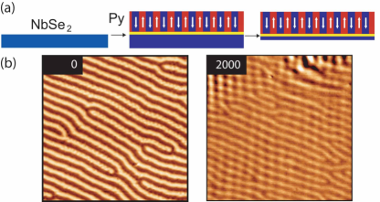
The bilayer for present study was prepared using the method elaborated in Ref. Karapetrov et al. (2005). 20 nm thick SiO2 insulating thin film was sputtered using RF magnetron on a freshly cleaved high quality NbSe2 single crystals (Tc=7.2K, RRR=40). This layer was covered with a m thick Py (Fe20Ni80) overlayer using DC magnetron sputtering from a single target (Fig. 1a). As-prepared sample was attached to a conducting substrate with the ferromagnetic layer down. The surface of NbSe2 single crystal was cleaved successively until the color of the surface started changing. This is a first indication that the thickness of the NbSe2 top layer is within the wavelength of the visible light. By further cleaving the sample the areas of different color could be obtained that signify different thickness of the superconductor Novoselov (2005). The final thickness used in the STM studies in this work was c.a. 0.4 m and this value was verified by cross-sectional cut of the sample using focused ion beam etching and scanning electron microscopy metrology.
The thick Py film forms narrow magnetic stripe domain pattern with a period comparable to the film thickness Saito (1964); Spain (1963) (Fig. 1b). The period of the domain structure is proportional to the thickness of the Py film. The magnetic stripe domain structure is insensitive to magnetic field applied perpendicular to the film’s surface up to 400 Oe, but forms checkerboard domains in higher fields (Fig. 1b). In our theoretical calculations, we used the dependence cm, following from Ref. Szymczak (1968) and estimated magnetization of the film G, exchange constant erg/cm and uniaxial anisotropy constant erg/cm3.
The theoretical simulations of the described structure were performed within Ginzburg-Landau (GL) theory. We solve self-consistently a set of mean field differential equations for the order parameter and the vector potential :
| (1) | |||
| (2) |
The latter is the Maxwell-Ampère equation with a current density . GL constant equals the ratio between the magnetic field penetration depth and coherence length , and is in general very large for NbSe2 samples. In above expressions, all distances are expressed in units of , the vector potential in , and the order parameter in with , being the GL coefficients. For more details on the numerics and implementation of periodic boundary conditions we refer to Ref. Milošević and Peeters (2004). Note that virial theorem requires integer number of flux quanta in the simulation region with periodic boundary, and we accommodate that by fixing the width of simulation region to the period of magnetic domain structure , and the length is fitted (at ) according to the applied magnetic field.
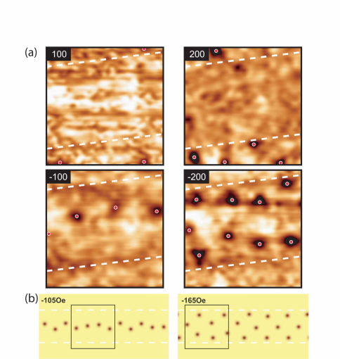
In STM measurements, the vortex images were obtained by spatially mapping the tunneling conductance value at the edge of superconducting energy gap at 4.2 K Karapetrov et al. (2006). In Fig. 2, we show the local density of states (LDOS) map of m2 area on NbSe2 surface. Fig. 2 (a) shows a slightly distorted vortex chain at -100 Oe. The effective magnetic field above each domain is a sum of the contributions of the applied magnetic field and the field due to the local magnetization of the Py. In the case when these two contributions are of the same sign the effective fields are enhanced, and when they are of opposite sign the two contributions cancel each other. From our map it is obvious that the central part of the image is above a domain that has a “negative” polarity, i.e. the domain is collinear with the negative applied magnetic field. One expects that at 100 Oe the average vortex distance should be m, and instead, at -100 Oe the vortices form a quasi-1D chain state with average distance of m. No vortices are observed at +100 Oe in the same area, being pinned at the adjacent domain.
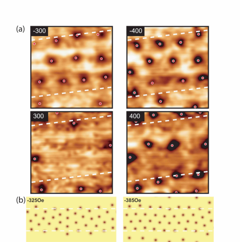
Further increase of the negative applied field leads to increase in vortex density and formation of chain states similar to ones predicted in Ref. Brongersma et al. (1993) and observed earlier in patterned superconducting NbSe2 Karapetrov et al. (2006). The chains consist of periodically spaced vortices in the middle of the stripe domain. As magnetic field increases so does the vortex density, leading to smaller inter-vortex spacing within a single chain. This process is continuous until a critical point leading to geometrical ordering transition and formation of double chains (Fig. 2(a) at -200 Oe) and triple chains (Fig. 5(a) at -300 Oe). The similarities in vortex ordering and geometrical phase transitions with the case of strong 1D confinement potential Brongersma et al. (1993); Karapetrov et al. (2006) end at this point. Further, with the help of simulations, we focus on the subtle but important effects that are specific to the nature of our confining potential.
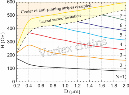
We take advantage of the numerical simulations to reconstruct the vortex phase diagram of the magnetically coupled S/F bilayer system. Numerical solution of Eqs. (1-2) minimizes the Gibbs free energy of the sample, and Fig. 4 shows the main outline of the ground-state phase diagram as a function of thickness of the Py film. Since this is a 2D calculation, the stray field of the Py film has been averaged over given thickness of NbSe2 film, and as such put into Eqs. (1-2). The simulation region was large, and simulations were performed for nm and K. The vortex states obey the imposed linear confinement and form multiple vortex chains ( of them) along the stripe domain with out-of-plane magnetization parallel to the applied field (as expected from the theory of magnetic pinning of vortices, see e.g. Ref. Milošević and Peeters (2003)). However, it should be emphasized that in reality transitions between different -chain states are not of first order. In increasing field, added vortex causes local chain instability, by changing locally the transverse “optical” mode Liu et al. (2003). More instabilities eventually lead to a new ordered -chain state via a so-called ”zig-zag” type transition characteristic for quasi-1D Wigner crystals Piacente et al. (2004). These transverse instabilities leading to different ordering are evident in Fig. 2, where calculated vortex structures for the case of m are given for and chain rearrangement, in comparison with experimentally obtained snapshots of vortex configurations.
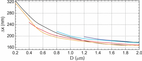
Note however that vortex spacing along the chain prior to the transition remains larger than , a value predicted for transition in Ref. Brongersma et al. (1993). In Fig. LABEL:Figure4 we show the calculated vortex spacing along the chain prior to the formation of a new chain as a function of the thickness of the magnetic film (i.e. proportional to the domain width). The main conclusions following from Fig. LABEL:Figure4 are that (i) threshold vortex spacing decreases with thickness of the magnetic film, but saturates for m, and (ii) is very weakly dependent of the number of chains , contrary to findings of Ref. Brongersma et al. (1993). Note that in quasi-1D confined classical systems, with hard-wall lateral boundaries, also decreases with (see e.g. Haghgooie and Doyle (2004)), while in our system lateral confinement is of parabolic type (where decrease of with is slower Piacente et al. (2004)).
The discrepancy from the model Brongersma et al. (1993) is caused by the non-rigid lateral confinement of the vortex chains. Namely, the superposition of applied magnetic field and the stray field of the magnetic domains leads to slow expansion of the confinement potential for the superconducting vortices. From the magnetic force microscopy images at room temperature Belkin et al. (2008a) and the STM maps in Fig. 2 we can reconstruct the position of the stripe domains under the NbSe2 layer, and the domain boundaries are outlined with dashed lines in Figs. 2-4. However, beyond one notices that vortex chains may already occupy areas slightly beyond the domain boundaries. Therefore, with increasing magnetic field, not only that new vortices are added to the system, but confinement potential is broadened as well. This leads to further lateral instability of the chains, in the areas of strongest interaction with effective confinement. Moreover, the attractive force acting on newly added vortices may gradually become comparable to the overall long-range interaction with earlier formed vortex chains, forcing the new vortices to reside in the anti-pinning channel above the magnetic domain of opposite polarity. This is shown in Fig. 5, for fields Oe in experiment and 325 Oe in the simulation. Due to competing interactions, several vortices are ‘levitating’ above the energetically non-favorable domain. Beyond the field of 325 Oe in the simulations, we were unable to recover the linear chain state, unless we had the commensurate number of vortices in each chain. In every other case, the attempt of the large number of vortices to form an Abrikosov lattice in competition with linear confinement, resulted in a sinusoidal-like modulation of the vortex structure, such as one shown in Fig. 5(b).
Further increase of the applied field leads to a larger number of vortices in the chains as well as above the anti-pinning domain. At certain conditions vortices at the anti-pinning channel may form a 1D structure, being equally repelled (on average) by chain structures from both adjacent domains. This is a very peculiar state, since vortex repulsion in the anti-pinning domain is strongest in its central region. The existence of such vortex ordering is verified in both theory (at Oe) and experiment (at 400 Oe), as shown in Fig. 5. Beyond this field, vortices have little difficulty trespassing to the anti-pinning domain, which finally leads to a somewhat distorted Abrikosov lattice across the whole film.
To summarize, we studied the Abrikosov vortex configurations in magnetically coupled superconductor-ferromagnet bilayers. We elucidate the mechanism of quasi-1D topological vortex phase transitions in this system by theoretical simulations and STM vortex imaging. We demonstrate that transitions between 1D ordered vortex phases are accompanied by local transverse instabilities resulting in local vortex disorder. This, in combination with magnetic field-relaxed confinement, leads to lower threshold vortex densities for the geometrical transitions than in strongly confined systems such as superconducting stripes and hard-wall classical clusters. At higher magnetic fields the change of number of vortices is accompanied with the change in confinement potential resulting in nonlinear system response and vortex chain formation above the domains with opposite polarity. As a result, we found the ‘levitation’ of vortices above the magnetic domains of opposite polarity, as well as vortex chain formation in this energetically unfavorable region, while the earlier formed chains are being sinusoidally distorted from the equilibrium Abrikosov vortex lattice.
This work as well as the use of the Center for Nanoscale Materials and the Electron Microscopy Center at Argonne National Laboratory were supported by UChicago Argonne, LLC, Operator of Argonne National Laboratory (“Argonne”). Argonne, a U.S. Department of Energy Office of Science laboratory, is operated under Contract No. DE-AC02-06CH11357. M.V.M. and F.M.P. acknowledge support from the Flemish Science Foundation (FWO-Vl), the Belgian Science Policy, the JSPS/ESF-NES program, the ESF-AQDJJ network, and the Vlaanderen-USA bilateral program.
References
- Buzdin (2005) A. I. Buzdin, Rev. Mod. Phys. 77, 935 (2005); I. F. Lyuksyutov and V. L. Pokrovsky, Adv. Phys. 54, 67 (2005); F. S. Bergeret, A. F. Volkov, and K. B. Efetov, Rev. Mod. Phys. 77, 1321 (2005); Y. A. Izyumov, Y. N. Proshin, and M. G. Husainov, Sov. Phys.–Uspekhi 45, 109 (2002); M. Velez, J. I. Martin, J. E. Villegas, A. Hoffmann, E. M. Gonzalez, J. L. Vicent, and I. K. Schuller, J. Magn. Magn. Mater. 320, 2547 (2008).
- Yang et al. (2004) Z. Yang, M. Lange, A. Volodin, R. Szymczak, and V. V. Moshchalkov, Nat. Mater. 3, 793 (2004).
- Bulaevskii et al. (2000) L. N. Bulaevskii, E. M. Chudnovsky, and M. P. Maley, Appl. Phys. Lett. 76, 2594 (2000).
- Gillijns et al. (2005) W. Gillijns, A. Y. Aladyshkin, M. Lange, M. J. V. Bael, and V. V. Moshchalkov, Phys. Rev. Lett. 95, 227003 (2005).
- Stamopoulos et al. (2005) D. Stamopoulos, M. Pissas, and E. Manios, Phys. Rev. B 71, 014522 (2005).
- Milošević and Peeters (2005) M. V. Milošević and F. M. Peeters, Europhys. Lett. 70, 670 (2005).
- Vlasko-Vlasov et al. (2008) V. V. Vlasko-Vlasov, U. Welp, G. Karapetrov, V. Novosad, D. Rosenmann, M. Iavarone, A. Belkin, and W. K. Kwok, Phys. Rev. B 77, 134518 (2008).
- Belkin et al. (2008a) A. Belkin, V. Novosad, M. Iavarone, J. Fedor, J. E. Pearson, A. Petrean-Troncalli, and G. Karapetrov, Appl. Phys. Lett. 93, 072510 (2008a).
- Brongersma et al. (1993) S. H. Brongersma, E. Verweij, N. J. Koeman, D. G. de Groot, R. Griessen, and B. I. Ivlev, Phys. Rev. Lett. 71, 2319 (1993).
- Guimpel et al. (1988) J. Guimpel, L. Civale, F. de la Cruz, J. Murduck, and I. K. Schuller, Phys. Rev. B 38, 2342 (1988).
- Andre et al. (2000) M. O. Andre, M. Polichetti, H. Pastoriza, and P. H. Kes, Physica C 338, 179 (2000).
- Kokubo et al. (2002) N. Kokubo, R. Besseling, V. M. Vinokur, and P. H. Kes, Phys. Rev. Lett. 88, 247004 (2002).
- Stan et al. (2004) G. Stan, S. B. Field, and J. M. Martinis, Phys. Rev. Lett. 92, 097003 (2004).
- Grigorieva et al. (2004) I. V. Grigorieva, A. K. Geim, S. V. Dubonos, K. S. Novoselov, D. Y. Vodolazov, F. M. Peeters, P. H. Kes, and M. Hesselberth, Phys. Rev. Lett. 92, 237001 (2004).
- Karapetrov et al. (2006) G. Karapetrov, J. Fedor, M. Iavarone, D. Rosenmann, and W. K. Kwok, Phys. Rev. Lett. 95, 167002 (2006).
- Karapetrov et al. (2005) G. Karapetrov, J. Fedor, M. Iavarone, M. T. Marshall, and R. Divan, Appl. Phys. Lett. 87, 162515 (2005).
- Belkin (2008b) A. Belkin, V. Novosad, M. Iavarone, J. Fedor, J. E. Pearson, and G. Karapetrov, Phys. Rev. B 77, 180506 (2008b).
- Novoselov (2005) K. S. Novoselov, D. Jiang, F. Schedin, T. J. Booth, V. V. Khotkevich, S. V. Morozov, and A. K. Geim, Proc. Nat. Acad. Sci. USA 102, 10451 (2005).
- Saito (1964) N. Saito, H. Fujiwara, and Y. Sugita, J. Phys. Soc. Japan 19, 1116 (1964).
- Spain (1963) R. Spain, Appl. Phys. Lett. 3, 208 (1963).
- Szymczak (1968) R. Szymczak, J. Appl. Phys. 39, 875 (1968).
- Milošević and Peeters (2004) M. V. Milošević and F. M. Peeters, Phys. Rev. Lett. 93, 267006 (2004).
- Reichhardt et al. (2006) C. J. O. Reichhardt, A. Libäl, and C. Reichhardt, Phys. Rev. B 73, 184519 (2006).
- Milošević and Peeters (2003) M. V. Milošević and F. Peeters, Phys. Rev. B 68, 094510 (2003).
- Liu et al. (2003) B. Liu, K. Avinash, and J. Goree, Phys. Rev. Lett. 91, 255003 (2003).
- Piacente et al. (2004) G. Piacente, I. V. Schweigert, J. J. Betouras, and F. M. Peeters, Phys. Rev. B 69, 045324 (2004).
- Haghgooie and Doyle (2004) R. Haghgooie and P. S. Doyle, Phys. Rev. E 70, 061408 (2004).