Cyclotron effect on coherent spin precession of two-dimensional electrons
Abstract
We investigate the spin dynamics of high-mobility two-dimensional electrons in GaAs/AlGaAs quantum wells grown along the and directions by time-resolved Faraday rotation at low temperatures. In measurements on the -grown structures without external magnetic fields, we observe coherent oscillations of the electron spin polarization about the effective spin-orbit field. In non-quantizing magnetic fields applied normal to the sample plane, the cyclotron motion of the electrons rotates the effective spin-orbit field. This rotation leads to fast oscillations in the spin polarization about a non-zero value and a strong increase in the spin dephasing time in our experiments. These two effects are absent in the -grown structure due to the different symmetry of its effective spin-orbit field. The measurements are in excellent agreement with our theoretical model.
pacs:
39.30.+w 73.20.-r 85.75.-d 71.70.EjA key issue in the semiconductor spintronics Fabian ; Fabian07 is the dynamics of spins of carriers in low-dimensional structures. Advances in the technology allow manufacture of very clean two-dimensional electron systems (2DES) based on GaAs/AlGaAs heterostructures where carriers can move ballistically over distances of several micrometers and the time between scattering events is on the order of 100 ps. The main spin dephasing mechanism in these structures is the Dyakonov-Perel’ (DP) mechanism dp , driven by the wave vector -dependent spin-orbit (SO) fields present due to bulk inversion asymmetry (Dresselhaus field) bia and structure inversion asymmetry (Rashba field)sia . By growing 2DES along different crystallographic directions, the symmetry of the SO fields can be changed, leading to strong modifications of the electron spin dynamics: in [110]-grown 2DES, for example, the Dresselhaus field points along the growth direction, regardless of the electron wave vector. Electron spins aligned along the growth direction experience no torque, and the DP mechanism is therefore effectively suppressed for this spin orientation dp1 ; Ohno , while it is still the main spin dephasing channel for any other spin orientation, leading to a strong orientational anisotropy of the spin dephasing time (SDT). wugo ; Dohrmann In the presence of an additional Rashba field caused by an asymmetrical placement of the modulation doping layers Belkov_PRL ; Olbrich_PRB or tuned by an external gate voltage Karimov , and oriented along the 2DES plane regardless of growth direction, the SDT is reduced drastically. By contrast, in [001]-grown 2DES Dresselhaus and Rashba fields are in-plane, hence, the spin -component dephasing is relatively fast, and their interference may also lead to a strong orientational anisotropy of spin dephasing. Averkiev ; Averkiev06
Two regimes of the DP mechanism are typically considered. The first is the ‘motional narrowing regime’, where the electron spin precesses about the SO field only by a small angle in between scattering events. The other one is the ‘weak scattering regime’ where the spin can precess one or more full revolutions before the electron is scattered. At liquid-helium temperatures and above, most 2DES are in the motional narrowing regime. In high-mobility samples at low temperatures, however, the weak scattering regime becomes accessible in the experiment and the precession of the electron spins about the internal SO fields is observable as coherent oscillations of the -component of the spin polarization. Brand ; Leyland07 ; stich Unlike the ‘motional narrowing regime’ where the cyclotron effect of an external magnetic field simply results in a spin relaxation slow-down Ivchenko73 , in high-mobility systems the regular change in the electron wave vector caused by the cyclotron rotation was predicted to have a dramatic effect on spin dynamics. Glazov_SSC ; Glazov_EPL
Here, we present a study on the electron spin dynamics in high-mobility 2DES at low temperatures in zero and non-quantizing perpendicular fields. We observe coherent zero-field oscillations, and fast, small-amplitude spin beats in perpendicular fields which stem from the cyclotron rotation of the SO field. Our samples were grown by molecular beam epitaxy on and -oriented semi-insulating GaAs substrates. The active region in all three samples is a GaAs-Al0.3Ga0.7As single quantum well (QW). While sample B is a conventional, one-side modulation-doped QW, samples A and C utilize a complex growth structure (similar to that used in Ref. Umansky, ) to achieve a symmetrical, double-sided doping profile. Sample properties are listed in Table 1. For optical measurements in transmission geometry, the samples were glued onto sapphire substrates with an optical adhesive, and the substrate and buffer layers were removed by selective etching.
| # | growth | width | density | mobility | ||
|---|---|---|---|---|---|---|
| axis | (nm) | (cm-2) | ( cmVs) | (ps) | (ps) | |
| A | (001) | 30 | 2.97 | 14.8 | 563 | 88 |
| B | (001) | 20 | 2.1 | 1.6 | 61 | 22 |
| C | (110) | 30 | 3.4 | 5.1 | 194 | 130 |
In the time-resolved Faraday rotation (TRFR) measurements, a mode-locked Ti:Sapphire laser was used, which allowed for a near-resonant excitation of electrons into the conduction band slightly above the Fermi energy of the 2DES. Details of the experimental setup are published elsewhere. Stich_PRB The TRFR measurements were performed in a split-coil magnet cryostat with a 3He insert, allowing for sample temperatures between 400 mK and 4.5 K.
First, we study the spin dynamics in all three samples in the absence of an external magnetic field. Figures 1(a)-(c) show TRFR traces measured on samples A-C at low temperatures. In samples A and B, a strongly damped oscillation is clearly observable in the measurements at 4.5 K. In both samples, the decay constant of this oscillation becomes longer, and the oscillation frequency increases, as the sample temperature is lowered. In contrast, sample C does not show oscillatory spin dynamics, even at low temperatures. Instead, the TRFR signal decays partially within the measurement window and then approaches a nonzero value.
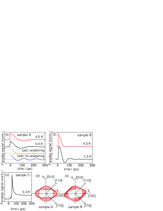
In samples A and B the SO interaction-induced effective magnetic field lies in the QW plane. In the weak scattering regime the electron spin precesses around and the pronounced oscillations are observed. Here, is the effective magnetic field for electrons at the Fermi level and is the single electron momentum scattering time which has additive contributions from disorder and phonon scattering processes, as well as from the electron-electron scattering. gi The damping of the oscillations is caused by these scattering processes and by the anisotropy of the spin splitting. Glazov_SSC In the symmetric sample A, the Dresselhaus term contains first and third angular harmonics as is schematically shown in Fig. 1(d) since for the given sample parameters, the Fermi wave vector and the inverse quantum well width are comparable. The spin beats are damped due to the spin splitting anisotropy and electron-electron scattering: it is seen that the change in sample temperature from 400 mK to 4.5 K (Fig. 1(a)), which reduces the electron mobility by a factor of two, only weakly reduces the decay constant of the coherent oscillation from 74 ps at 400 mK to 63 ps at 4.5 K. As the calculated traces in Fig. 1(a) show, the spin splitting anisotropy alone is not sufficient to explain the damping, therefore, electron-electron scattering is likely to be the dominant scattering process in this sample also at 400 mK. The weak temperature effect on the beats may be attributed to the heating of the electron gas by the excitation which leads to a reduced difference in the electron-electron scattering times at the two measurement temperatures.
In sample B, which has a one-side doping layer, Rashba and Dresselhaus fields are present; their relative strength was determined by magnetoanisotropy measurements Stich_PRBRC07 to be about . The symmetry of their vector sum is shown in Fig. 1(e). The average amplitude of this effective SO field is larger than for sample A, due to the Rashba effect and the enhancement of the Dresselhaus term for the thinner QW. Leyland07 Accordingly, the precession frequency of the coherent beats is larger. In this sample, which has a lower mobility than sample A, the coherent oscillation is predominantly damped due to momentum scattering. Its influence is observable in the strong temperature dependence of the decay constant, which is reduced from 35 ps to 18 ps as the temperature is increased from 1.3 K to 4.5 K due to the reduced electron mobility, and the increasing importance of electron-electron scattering (Fig. 1(b)). In this sample, the ensemble momentum scattering time , which may be extracted from mobility measurements, and the electron-electron scattering time (see Table 1), are comparable at 4 K.
The situation is drastically different in a symmetric -grown QW, sample C (Fig. 1(c)). Here, the Dresselhaus field points along the growth direction and is therefore parallel to optically oriented electron spins. Due to the symmetric doping, there is no pronounced Rashba field present in this sample, therefore, the injected electron spins do not precess coherently. The partial decay of the Faraday signal in this sample is due to photocarrier recombination and the BAP mechanism. bap In symmetrically-grown samples, very long spin dephasing times have been observed, and other dephasing mechanisms may be important. Dohrmann ; Muller09 The limit for spin dephasing in these systems is due to random Rashba fields caused by fluctuations in the remote doping density. Sherman_Wu
We now turn to measurements in weak perpendicular magnetic fields and focus on sample A.
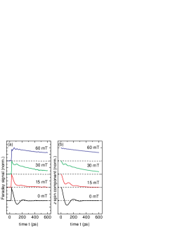
Figure 2 (a) shows a series of TRFR traces measured on sample A for various perpendicular magnetic fields at 400 mK. Two features are clearly visible: at , fast, damped spin beats become apparent in the Faraday signal, their frequency increases with the perpendicular magnetic field. The amplitude of these beats is small, and for mT, the Faraday signal does not cross the zero line. Additionally, the decay of the Faraday signal becomes slower with increasing magnetic field, and after the spin beats are damped out, a longer-lived tail of the Faraday signal is observed.
The quantitative description of the electron spin dynamics in a magnetic field is carried out within the standard kinetic approach. Glazov_SSC ; gi The kinetic equation for the spin distribution function in a magnetic field applied along the growth axis can be written as . Here is the cyclotron frequency, where and are the electron charge and effective mass, respectively, is the angle between and the axis, and is the collision integral. The main features of the spin dynamics can be understood from the solution of the kinetic equation in the case of isotropic spin splitting under the assumption : assump
| (1) |
where , , , , . In the general case of anisotropic spin splitting and non-zero temperature Eq. (1) approximately holds for the averaged spin if and are replaced by the effective values containing an additional contribution due to the spread of spin precession frequencies. Glazov_SSC According to Eq. (1), the -component of the spin, , demonstrates damped oscillations with the combined frequency , superimposed on the exponential decay. The enhancement of the spin precession frequency is a result of the electron cyclotron motion. The cyclotron rotation of results in the modulation of the SO field and the electron spin experiences a torque being a geometrical sum of and . Glazov_SSC
The damping of the spin beats occurs at time scale , while the decay of the average spin value takes a much longer time . At , the spin relaxation time passes to the ‘motional narrowing’ expressions Ivchenko73 ; glazov04 because the variation of the SO field caused by the cyclotron rotation is much faster than the spin precession in the field . The results of a numerical solution of the kinetic equation, with allowance for anisotropic spin splitting, model_param are shown in Fig. 2(b). The experimental data are well reproduced by such a modeling.
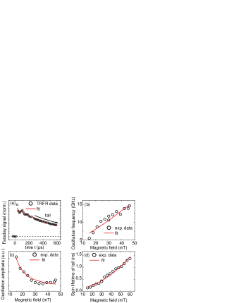
For further comparison between experiment and theory we plot the amplitude and frequency of the fast spin beats, as well as the decay constant of the tail, by fitting the experimental data by Eq. (1), as it is shown in Fig. 3 (a). The summary of the fit parameters is given in panels (b)-(d) of Fig. 3. In Fig. 3 (b), we plot the observed frequency as a function of the applied magnetic field. The best fit using the geometric sum formula is shown as a solid red line. It is in good agreement with the experimental data, however, the effective cyclotron frequency extracted from the fit is about larger as compared to the calculated one. Such a difference can be caused by the anisotropy of the spin splitting. The beats at low magnetic field are damped on the same timescale as the coherent zero-field oscillation in agreement with Eq. (1) due to the anisotropy of the SO field and the momentum randomization due to disorder and electron-electron scattering. Leyland_ee ; gi
The spin beats amplitude systematically decreases with the applied magnetic field, as shown in Fig. 3(c), because fast cyclotron rotation of suppresses the spin precession around . The red solid line in Fig. 3 (c), which represents a fit to the data using Eq. (1), is in good agreement with the experimental data.
Finally, we focus on the magnetic field dependence of the long-lived ‘tail’ of the Faraday signal. The experimental data in Fig. 3(d) demonstrate that the decay time of this tail increases quadratically as a function of the perpendicular field. A fit according to Eq. (1) (solid red line in Fig. 3) leads to a rather small scattering time ps, which is an evidence of the strong spin splitting anisotropy in the sample. The kinetic model with allowance for the spin splitting anisotropy model_param (not shown in the Figure) is in excellent agreement with the experimental findings.
In the symmetric [110]-grown QW, where the SO field points out of the QW plane, this precession is absent, as the optically oriented electron spins are parallel to the externally applied magnetic field and the SO field. TRFR measurements on sample C at low temperatures in weak perpendicular fields (not shown) show no spin beats, confirming that there is no significant Rashba field in this sample.
In conclusion, we have investigated the electron spin dynamics in high-mobility two-dimensional electron systems grown in different crystallographic directions at low temperatures. In measurements without applied magnetic field, pronounced coherent oscillations of the electron spin polarization about the SO field are observed in the -grown samples. In the same samples non-quantizing perpendicular magnetic fields make the spin beats faster and strongly suppress the decay of the net spin polarization due to the cyclotron rotation of the effective SO field. In symmetric -grown samples the SO field does not result in a spin component rotation and, consequently, no cyclotron effect is observed. The experimental observations are in good agreement with calculations based on a kinetic equation approach.
The authors would like to thank E.L. Ivchenko for very fruitful discussions. Financial support by the DFG via SPP 1285 and SFB 689, University of Basque Country Grant GIU07/40, RFBR, Dynasty Foundation and President grant for young scientists is gratefully acknowledged.
References
- (1) I. Zutic, J. Fabian, and S. Das Sarma, Rev. Mod. Phys. 76, 323 (2004), and references therein.
- (2) J. Fabian et al., Acta Physica Slovaca 57, 565 (2007), and references therein.
- (3) M. I. D’yakonov and V. I. Perel’, Zh. Éksp. Teor. Fiz. 60 1954 (1971) [Sov. Phys. JETP 33, 1053 (1971)].
- (4) G. Dresselhaus, Phys. Rev. 100, 580 (1955).
- (5) Y. A. Bychkov and E. I. Rashba, Pis’ma Zh. Éksp. Teor. Fiz. 39, 66 (1984) [Sov. Phys. JETP Lett. 39 78 (1984)].
- (6) M.I. D’yakonov and V.Yu. Kachorovskii, Fiz. Tekh. Poluprovodn. 20, 178 (1986) [Sov. Phys. Semicond. 20, 110 (1986)].
- (7) Y. Ohno et al., Phys. Rev. Lett. 83, 4196 (1999).
- (8) M. W. Wu amd M. Kuwata-Gonokami, Solid State Commun. 121, 509 (2002).
- (9) S. Döhrmann et al., Phys. Rev. Lett. 93, 147405 (2004).
- (10) V. V. Belkov et al., Phys. Rev. Lett. 100, 176806 (2008).
- (11) P. Olbrich et al., Phys. Rev. B 79, 245329 (2009).
- (12) O. Z. Karimov et al., Phys. Rev. Lett. 91, 246601 (2003).
- (13) N. S. Averkiev and L. E. Golub, Phys. Rev. B 60, 15582 (1999).
- (14) N. S. Averkiev et al., Phys. Rev. B 74, 033305 (2006).
- (15) M. A. Brand et al., Phys. Rev. Lett. 89, 236601 (2002).
- (16) W. J. H. Leyland et al., Phys. Rev. B 76, 195305 (2007)
- (17) D. Stich et al., Phys. Rev. Lett. 98, 176401 (2007).
- (18) E.L. Ivchenko, Sov. Phys. Solid State 15, 1048 (1973).
- (19) M.M. Glazov, Solid State Comm. 142, 531 (2007).
- (20) M.M. Glazov and E.Ya. Sherman, Europhys. Lett. 76, 102 (2006).
- (21) V. Umansky et al., Journal of Crystal Growth, 311, 1658 (2009).
- (22) D. Stich et al., Phys. Rev. B 76 76, 205301 (2007).
- (23) M.M. Glazov and E.L. Ivchenko, JETP Lett. 75, 403 (2002); JETP 99, 1279 (2004). M.M. Glazov, Phys. Solid State 45, 1162 (2003).
- (24) D. Stich et al., Phys. Rev. B 76 073309 (2007).
- (25) G. L. Bir, A. G. Aronov, and G. E. Pikus, Zh. Éksp. Teor. Fiz. 69, 1382 (1975) [Sov. Phys. JETP 42, 705 (1975)].
- (26) G. Müller et al., Phys. Rev. Lett. 101, 206601 (2008).
- (27) M.M. Glazov and E.Ya. Sherman, Phys. Rev. B 71, 241312 (RC) (2005); Y. Zhou and M. W. Wu, preprint arXiv:0910.0066v1 (unpublished)
- (28) For the parameters used in calculations model_param these quantities are: , .
- (29) M.M. Glazov, Phys. Rev. B 70, 195314 (2004).
- (30) The scattering time ps, the Dresselhaus SO field , is the angle between and , ps-1, the scattering potential is taken to be smooth.
- (31) W. J. H. Leyland et al. Phys. Rev. B 75, 165309 (2007).