Plans for ANDA Online Computing
Abstract
The ANDA experiment will not use any hardware trigger, i.e. all raw data are streaming in the data acquisition with a bandwidth of 280 GB/s. The ANDA Online System is designed to perform data reduction by a factor of 800 by reconstruction algorithms programmed in VHDL (Very High Speed Integrated Circuit Hardware Description Language) on FPGAs (Field Programmable Gate Arrays).
keywords:
Data Acquisition Systems; Trigger Systems1 Introduction
The ANDA experiment at the future FAIR (Facility for Antiproton and Ion Resarch) facility at GSI Darmstadt, Germany, will investigate + and + collisions. It will be a fixed target experiment using a frozen hydrogen pellet target and a beam of stored and cooled antiprotons with a beam momentum 15 GeV/c. The beam momentum resolution will be / and the luminosity 21032 cm-2s-1. Among many other topics, the physics program will cover the production of charmonium states in the reaction . If one adjusts the beam energy to resonant / production for one year, and assumes a duty factor of 50%, this will correspond to a number of 2109 /. In particular, ANDA will be able to measure the width of charmonium states in the order of 100 keV. Other physics topics [1] are spin physics (e.g. measurement of generalized parton distributions) and hypernuclear physics (e.g. production of double hypernuclear nuclei).
ANDA will be one of the very few experiments worldwide not using any hardware trigger. All raw data will be streaming into the data acquisition (DAQ), and need to be filtered before being recorded to tape. The reason for this approach is, that signal events such as charmonium events in have a very similar event topology compared to background events such as , , . There are no straight-forward trigger criteria such as number of charged tracks or number of neutral clusters in the calorimeter. Thus, the only way of data reduction is online reconstruction on a farm with high computing performance. Algorithms can be e.g. invariant mass reconstruction on a particular charmonium state, and then applying e.g. a cut on a signal in the invariant mass in the ANDA online system.
2 The ANDA Experiment
2.1 The ANDA Detector
One of the important tasks to be performed by the ANDA online system will be the online particle indentification (PID), i.e. assigning a probability that a given charged track is a pion, kaon, proton, electron or muon. For this purpose, the data of the central ANDA erenkov detector DRC (Detector for internally reflected erenkov light) plays an essential role. It is a detector of DIRC type, i.e. using internally reflected erenkov light, consisting of 16 quartz bars (refractive index =1.47) of thickness =1.7 cm at a radius of =48 cm. For the central tracking system, two detector options are still under evaluation, both covering a radial range of =15-41 cm: a TPC (Time Projection Chamber) with 135 padrows and in total 135,169 pads of 22 mm2 size, or a STT (Straw Tube Tracker) with 4100 straw tubes with a tube radius =1 cm and a tube length =1.5 m, aranged in 15 double layers. Axial or skewed arrangement with respect to the beam axis is used, the skewed tubes being used for reconstruction. As part of the charged particle tracking near the target, an MVD (Micro Vertex Detector) consisting of 107 silicon pixels of size 100100 m2 and 7104 strips will be implemented. Further technical details about ANDA are described elsewhere [3].
2.2 The ANDA Data Acquisition System
With a high event rate of 2107 events/s and a raw event size of 4-20 kB (average 14 kB) ANDA will reach a data rate of 280 GB/s, the same order of magnitude as LHC experiments. As a difference, ANDA will not utilize any hardware triggers, but all raw data will be streamed to the DAQ. The baseline hardware platform for the ANDA DAQ system are Compute Nodes (CN), which will be described in detail in Ch. 4. The CNs will run online reconstruction algorithms programmed in VHDL on FPGAs for data reduction. All data digitization will be performed even in a stage before the CNs by the frontend electronics. Further details can be found elsewhere [4].
2.3 The ANDA Offline Computing System
The ANDA offline computing system is characterized by the large amount of data to be recorded. The final rate of events written to tape, at a stage behind the online data reduction system, is designed as 25 kHz. Assuming one year of data taking with a duty factor of 50%, this corresponds to 3.781011 events. With an estimated event size of 4 kB for DSTs111 DSTs will be the final reduced data set to be used for physics analyses. They contain e.g. 4-momenta of charged particles and neutral particles, but no reconstructed detector hit data anymore. (Data Summary Tapes), this corresponds to 1,5 Pbyte per year, or 378,000 DVDs. Including not only the DSTs, but also raw data, Monte-Carlo simulated data, reconstructed detector hit data etc., an estimate for the amount of data to be stored for only the first year of ANDA data taking will be 11.5 Pbyte. The offline computing will be performed on 2000 quad core CPUs for reconstruction, analysis and MC production.
2.4 The ANDA Online Computing System
From the constraints of the data acquisition system on the one side and of the offline computing system on the other side, the requirement for the online computing system can be defined, i.e. to reduce 2107 events/s raw data to 25103 event/s to be recorded to tape. This corresponds to a reduction factor of 800.
3 The HADES Experiment
First test beams for ANDA are envisaged for 2016. However, in particular the programming of the algorithms has already started. In order to be able to test online algorithmus already by now with real data, data from the HADES experiment were used, which studies dielectron events in +, + and + collisions, e.g. for investigating the behaviour of vector mesons inside nuclear matter. These vector mesons are detected by their decay into . Therefore HADES uses a RICH (Ring Imaging erenkov) detector for and identification. A ring finder is used online on the Level-2 trigger system. Charged tracks are identified in HADES by 4 drift chambers of trapezoidal shape with 30 of active area. 2 chambers are located in front and 2 behind a solenoid field for momentum measurement. Each drift chamber has 6 layers of wires, arranged in different angles for assigning a hit position and a track direction in each chamber. The HADES RICH detector has 55,296 readout pads of different geometrical shapes. Signal rings induced by or an have a fixed ring radius of 4 pads. Further details are described elsewhere [2]. Thus, several of the algorithmus for ANDA (e.g. ring finder and track finder) can be tested (with modifications) already on real data from HADES. In addition, HADES will be upgraded in the near future, in order to be prepared for heavy collision systems such as + collisions with high track multiplicity and thus higher required data bandwidth. Therefore a new data acquisition system and Level-2 trigger system has been proposed based on the CN, and the algorithms could be part of the upgraded trigger system.
4 The Compute Node
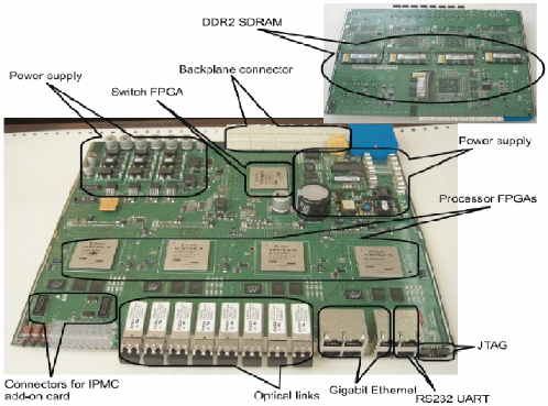
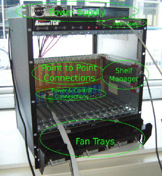
The proposed hardware unit to perform the online reconstruction at ANDA is the Compute Node (CN) and is shown in Fig. 1. The 14-layer printed circuit board has been developed by IHEP Beijing and the II. Physics Department of University Giessen. Each CN has five VIRTEX-4 FX-60 FPGAs (Field Programmable Gate Arrays). These FPGAs were chosen, as they combine high computing performance on the one hand and links for high bandwidth data transfer (RocketIO) on the other hand. One main feature of the board design is, that all FPGAs are connected point-to-point (see also below for details) in order to (a) combine data of different regions of one detector, processed by different FPGAs, and (b) combine data of different detectors within one event (i.e. event building). The programming of the FPGAs in VHDL is using XILINX ISE (Integrated Software Environment) Vers. 10.1. As an important note for algorithm design, FPGAs only provide fixed222There are softcores for floating point calculations for FPGAs available, however, the performance is not competetive to other architectures such as GPUs (see Ch. 5.6). point arithmetics. Thus, for any calculations such as matrix multiplications or trigonometric functions, (a) the parameter range has to be fixed (in order to limit it into a given fixed precision range), and (b) lookup tables have to be used instead of calculating arithmetics functions. Each Virtex-4 FX60 FPGA has two 300 MHz PowerPCs implemented as core, however, these are only used for slow control purposes and not for algorithms. In the current design, the Power PCs are booting Linux 2.6.27. In addition, each FPGA has 2 GB of DDR2 memory attached. The power negotiation and other slow control tasks between the CN and the ATCA shelf is based upon IPMI (Intelligent Platform Management Interface), implemented by an ATMEL ATmega2560 microcontroller on a CN add-on card [5]. The CN is designed as a board of the ATCA (Advanced Telecommunications Computing Architecture) standard. The ATCA shelf is shown in Fig. 1. In an ATCA shelf with a full mesh backplane, point-to-point connections from each CN to each other CN are wired. This avoids any bus arbitration. In addition to the high computing performance, the CN also provide high bandwidth interconnections. (a) All 5 FPGAs are connected pairwise (on the board) by one 32-bit general purpose bus (GPIO) and one full duplex RocketIO link. (b) 4 of 5 FPGAs have two RocketIO links routed to front panel using Multi-Gigabit Receivers (MGT) for optical links. (c) One of the 5 FPGAs serves as a router and has 16 RocketIO links through the full mesh backplane to all the other compute nodes in the same ATCA shelf. (d) All 5 FPGA have a Gigabit Ethernet Link routed to front panel. With the current design, the input bandwidth in one ATCA crate is 35 GB/s (14 CN, eight optical links each, operating at 2.5 Gbit/s). The output bandwidth is 2.6 GB/s (14 CN, five GB Ethernet links each, operating at 0.3 Gbit/s TCP performance, measured in [6]). All RocketIO links are currently operated with 2.5 Gbit/s, but the upgrade to 6.5 Gbit/s is envisaged, which would lead to even higher required reduction factors.
5 Algorithms
As mentioned above,
one of the important tasks to be performed by the online reconstruction
system at ANDA
will be the online particle identification (PID).
Several subtasks have to be accomplished
in order to achieve online PID assignment:
(a) An online ring finder for the DRC,
whereas erenkov photons propagate and are reflected inside
the quartz bars, then exit the bars at the downstream end,
and generate rings in the focal plane. After applying the
ring finder, the ring radius is known.
(b) a track finder and a track fitter for charged tracks,
with hits in the MVD and STT or TPC. After the stage of the
track fitter, the 3-momentum , and in particular the size of
the momentum = of the charged track is known.
(c) the extrapolation of the track onto the surface of the DRC
(in order to know, at which position the particle entered
the quartz bar).
(d) The erenkov angle
is a function of the two parameters and ,
and will be implemented as a lookup table in the online system.
(e) The final PID decision will be based upon a 2-dimensional
plot of vs. .
These algorithm steps will be performed the farm of CN,
which was described in Ch. 4.
In the following, examples will be given for track finder
and ring finder algorithms.
These algorithms are either tested with Monte-Carlo data
for ANDA or real data for HADES.
5.1 Track Finder Algorithm for HADES
A straight line track finder algorithm was tested with HADES data [6], using the 2 drift chambers in front of the field, i.e. 12 fired wires out of 2110 wires define a track. The algorithm was fully implemented on an FPGA. The processing time of the FPGA was compared to the CPU time of C program, performing the same track finder task, but running on a Xeon 2.4 GHz. For different fired wire multiplicities =10-400 a speedup of a factor 10.8-24.3 with respect to the reference was achieved.
5.2 Ring Finder Algorithm for HADES
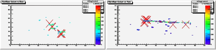
The existing HADES online ring finder system is implemented on a VME board with 12 Xilinx XC4028EX FPGAs [7]. As such it is part of the HADES Level-2 trigger system [8] and is in operation for several years of data taking [9] [10]. For an improved algorithm, to be implemented on the CN for the HADES upgrade project, the matching of a ring with a track (from the two drift chamber planes in front of the solenoid field) is foreseen [11]. Rings are only searched in regions-of-interest in the pad plane, given by areas of 1313 pads, centered around a pad, which’ position was found by track extrapolation. As the RICH uses a mirror, reflecting the erenkov light onto a pad plane in upstream direction, another coordinate transformation is required by usage of a lookup table. The pad plane for a typical signal and a typical background event is shown in Fig. 2. In order to quantitatively compare for the old and the new algorithm, the enrichment factor for lepton candidates for real data is evaluated. The enrichment factor is defined as the ratio of the efficiency333The efficiency is defined as the number of good positive triggers, divided by the sum of the numbers of good positive and false negative triggers. and the reduction factor444The reduction factor is defined as the sum of the numbers of good positive triggers and false positive triggers, divided by the number of downscaled triggers. For 12C+12C at 1 AGeV, using the new algorithm, the enrichment increases from 8.9 to 14.6, while the efficiency drops only from 93% to 91%. For 40Ar+40KCl at 1.756 AGeV with a higher track density the enrichment increases only from 1.7 to 2.0, again with a minor efficiency drop from 91% to 90%.
5.3 Track Finder Algorithm for ANDA
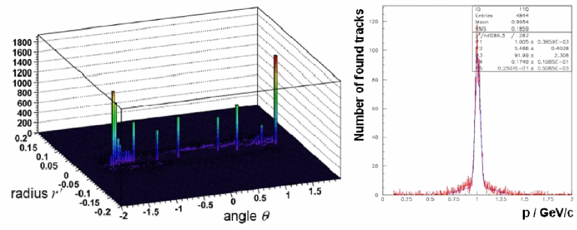
A helix track finder was developed for ANDA [12]. It was tested with Monte-Carlo simulated data for STT and MVD, i.e. 30 plus 7 hits per track. A field of =2 T was used with field maps correctly treating overlap with the magnetic dipole field in the ANDA forward spectrometer. The algorithm is based upon two steps. In the first step, a conformal transformation is applied. For every , coordinate of hits in the STT or MVD, new coordinates =(-)/ and =(-)/ with =(-)2+(-)2 are calculated. In a projection onto plane, helix tracks are circles. The conformal map transforms these circles into straight lines, which can be indentified easier as tracks by a track finder. In the second step, a Hough transform is applied. For any combination of (,) coordinates a straight line is formed, and the polar coordinates and are calculated. A normal vector with a 900 angle with respect to the line is constructed. The parameter is the distance from (=0,=0) along the normal vector to the line, and the parameter is the polar angle of the normal vector in the frame. Then all the new coordinates are filled into a 2-dimensional (,) histogram, and a peak finder is applied. A peak in this histogram corresponds to a found track. Fig 3 (left) shows the Hough space for 10 tracks of =1 GeV/c. The algorithm uses fix point arithmetics with 24 bit precision, in division and multiplication increased to 48 bit. The size of the Hough space was adjusted to 512512. The lookup table for the sinus function uses 128 values of 16 bit precision. Fig 3 (right) shows the momentum resolution for =1 GeV/c tracks. As a preliminary result [12] the efficiency of the online track finder is only 20% worse compared555The comparison between the online and the offline track finder algorithm was performed for events containing 10 tracks with the same momentum, e.g. =1 GeV/c, but random variation of the . to the offline algorithm. The resolution is only worse by a factor 2.5. For an online data reduction these values are acceptable.
5.4 Event Selector Algorithm for HADES
In order to test the speed of data moving on the CN, an event selector algorithm was tested with HADES data [13]. The algorithm was designed for (a) reading HADES binary events from DDR2 memory (a) partially decoding the event, (a) issuing an accept or reject decision, (a) discarding the event or writing it back to the DDR2 memory, depending on which decision was issued. For a DMA block size of 32 kB, for 100% (25%) accepted events the algorithm reached a throughput of 80 MB/s (150 MB/s).
5.5 Additional Algorithms
The matching of HADES tracks with the HADES time-of-flight and the HADES electromagnetic shower system requires track extrapolation through the field. As a preliminary result, for 40Ar+40KCl at 1.756 AGeV a reduction of 2 and an enhancement of 1.8 was achieved at an efficiency of 90% [14]. In addition, a track finder only based on hits of a silicon vertex detector (i.e. 2 layers of a pixel detector and 4 layers of a strip detector) was tested for the Belle II experiment [12].
5.6 Graphics Processing Units
As a novel approach for fast data processing, a track fitter based upon a conformal map transformation within the PandaRoot 2.0 framework [16] was tested on an NVidia Tesla C1060 Graphics Adapter [15]. The card has 240 cores and a single precision floating point performance of 933 GFLOPS. For the calculations on the GPU (Graphics Processing Unit), the NVidia CUDA framework [17] was used and interfaced to PandaRoot. The syntax of CUDA is very similar to the ANSI C programming language. The track finder for MVD and TPC was running in PandaRoot for tracks with generated =1 GeV and 50-2000 tracks/event. Then the hit data of the track candidates were transfered from the host PC to the GPU, where the track fitting was performed in 32 parallel threads in the next step. The fitted track data were transferred back to the PC. The performance of the complete algorithm was compared between running with and without GPU (i.e. host PC alone). A speed-up of a factor 68 [15] was achieved. Thus, GPUs seem to be attractive solution for high level processing which require floating point operations and are not possible on an FPGA.
Acknowledgements.
This work was supported by part by BMBF under contracts 06GI179 and 06GI180, GSI and DFG.References
- [1] The ANDA Collaboration, J. S. Lange et al., Int. Jour. Mod. Phys. A 24(2005)054503
- [2] The HADES Collaboration, G. Agakishiev et al., arXiv:0902.3478[nucl-ex], Eur. Phys. J. A41(2009)243
- [3] The ANDA Collaboration, M. Kotulla et al., ANDA Technical Progress Report, http://www-panda.gsi.de/archive/public/panda_tpr.pdf
- [4] I. Konorov, see contribution to these proceedings.
- [5] J. Lang, Diploma Thesis, University Giessen, 2008
- [6] M. Liu, Licentiate Thesis, KTH Stockholm, 2008
- [7] J. Lehnert, Ph. D. Thesis, University Giessen, 2000
- [8] M. Traxler, Ph. D. Thesis, University Giessen, 2001
- [9] A. Toia, Ph. D. Thesis, University Giessen, 2004
- [10] C. Kirchh bel geb. Gilardi, Ph. D. Thesis, University Giessen, 2008
- [11] J. Roskoss, Diploma Thesis, University Giessen, 2008
- [12] D. Münchow, Diploma Thesis, University Giessen, 2009
- [13] S. Yang, Master Thesis, KTH Stockholm, 2008
- [14] A. Kopp, TOF and Shower Trigger Algorithm and Online Matching with MDC Tracks, ANDA Frontend Electronics and Data Acquisition Workshop, Bodenmais, Germany, 24.04.2009
-
[15]
M. Al-Turany,
GPUs for event reconstruction in the FairRoot Framework,
CHEP09, Prague, Czech Republic, 21.-27.03.2009 - [16] http://panda-wiki.gsi.de/cgi-bin/view/Computing/PandaRoot
- [17] http://www.nvidia.com/object/cuda_get.html