A Tungsten / Scintillating Fiber Electromagnetic Calorimeter Prototype for a High-Rate Muon Experiment
Abstract
A compact and fast electromagnetic calorimeter prototype was designed, built, and tested in preparation for a next-generation, high-rate muon experiment. It uses a simple assembly procedure: alternating layers of 0.5-mm-thick tungsten plates and 0.5-mm-diameter plastic scintillating fiber ribbons. This geometry leads to a detector having a calculated radiation length of 0.69 cm, a Molière radius of 1.73 cm, and a measured intrinsic sampling resolution term of , in the range 1.5 to 3.5 GeV. The construction procedure, test beam results, and GEANT-4 comparative simulations are described.
keywords:
Electromagnetic calorimeter, tungsten scintillating fiber.PACS:
29.40.V, 13.35.B, 14.60.E, , , , , , ,
Contact person: .
1 Introduction
In the early 1980’s, the production of thin clad scintillating fibers led to development of fiber-based electromagnetic calorimeters. Early examples include the Omega inner calorimeter [1] and the Jetset forward calorimeter [2]. Both featured 1-mm-diameter fibers embedded in thin, grooved lead foils (Pb/SciFi). The fibers were orientated nearly head-on with respect to the incoming beam. Because fiber attenuation lengths exceed 1 m, applications involving long Pb/SciFi “bars” are also practical. The Jetset gamma barrel veto counter consisted of 24 trapezoidal 80-cm-long bars formed into a continuous cylindrical structure. The side-on calorimeters [3] for the E821 muon experiment were also made of Pb/SciFi with a radial readout of a large block into four summed photomultiplier tubes (PMTs). The KLOE collaboration constructed the largest installation of fiber-based calorimetry [4]. The entire detector, in collider-geometry, was based on very long Pb/SciFi bars. With special tooling and careful assembly, they achieved excellent energy and timing resolution.
This report details studies of a tungsten-based scintillating fiber (W/SciFi) calorimeter prototype having a 0.5-mm layer thicknesses. While the motivation is toward a new high-rate muon experiment, the generic properties of this type of dense, fast-response detector are of interest for other applications. The experimental conditions that motivate a calorimeter of this type will first be discussed, followed by our reports on beam and simulation tests of its performance.
In the Brookhaven muon experiment [5], 3.1 GeV/ polarized muons are injected and kicked onto orbits of a highly uniform magnetic storage ring [6]. As the muons circulate the ring, their spins rotate faster than the cyclotron frequency with a frequency difference proportional to the anomalous magnetic moment. Parity violation leads to a greater number of high-energy decay positrons being emitted in the direction of the muon spin. The positrons curl to the inside of the storage ring where they are intercepted by one of the 24 electromagnetic calorimeters, positioned adjacent to the storage ring aperture. The rate of positrons exceeding a given energy threshold—typically 2 GeV—is proportional to an exponential modulated with the spin precession frequency. Each storage ring “fill” is observed for s; the instantaneous rate varies from several MHz at the beginning of the fill to tens of Hz at the end of the fill. Because uncontrolled pileup of two nearly simultaneous events is a severe systematic error for the experiment, the calorimeter response must be capable of resolving two events separated by as little as 5 ns. Gain over the fill period must also remain very stable so that the threshold instability does not affect the fitted frequency.
The electromagnetic calorimeters for the E821 experiment used a Pb/SciFi design [2, 3]. Each calorimeter consisted of a monolithic block of 1-mm diameter fibers arranged in a near close-packed geometry within grooved lead alloy foils. The fractional composition of the detector was Pb:Sb:Fiber:Glue = (by volume), leading to a radiation length cm. The fibers were oriented radially so that the positrons would impact on the detector at large angles with respect to the fiber axis. Four lightguides directed the light to independent PMTs and the summed analog signal was processed by waveform digitizers. The 14-cm high by 22.5-cm radial by 15-cm deep calorimeter dimensions were largely dictated by the available space and the need to have a sufficient radial extension to intercept the positrons. The energy resolution requirement for is relatively modest, or better at 2 GeV.
A next-generation muon experiment [7]—with an aim of greater than four times improved precision—will require -fold increase in total stored muons. The muon injection rate will increase in most of the considered scenarios. This will lead to a higher instantaneous rate on the calorimeters, which will make the control of gain stability more difficult and will increase the magnitude of the pileup correction. The systematic errors associated with gain instability and pileup must each be reduced by a factor of . Accordingly, we have begun designing a new calorimeter that retains the fast response time of plastic scintillating fiber, but is made from an array of dense submodules where each is oriented roughly tangential to the muon orbit. This configuration will provide transverse segmentation and allow for multiple simultaneous shower identification. A 50:50 ratio of tungsten to scintillator (and epoxy) reduces shower transverse and longitudinal dimensions. The calculated [8] radiation length, cm, is of the length for the Pb/SciFi modules used in E821. Consequently, the modules can be made compact enough to free space for downstream readout in the highly constricted environment of the storage ring. The high density leads to a smaller radial shower size, which improves the isolation of simultaneous events. We find that using 0.5-mm layers gives an acceptable resolution close to at 2 GeV for our prototype; a non-trivial error contribution to this performance parameter arises from beam momentum spread, photo-electron yield and transverse leakage fluctuations. Therefore, the intrinsic detector response from sampling fluctuations alone is better.
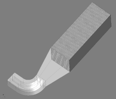
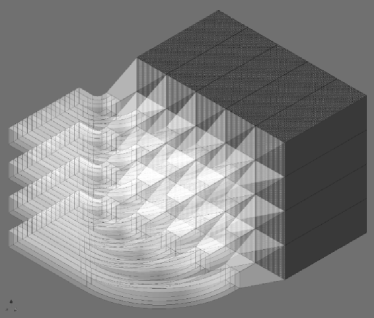
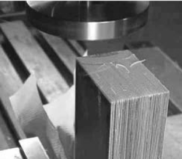
The cm3 prototype is shown in Fig. 1a. The full conceptual design array of cm3 modules is shown in Fig. 1b; 24 such arrays are required for the proposed muon experiment. The depicted lightguides in Fig. 1b imply a subdivision of the W/SciFi block into 20 independent readouts by PMTs (not shown), which must be placed sufficiently far away so as to minimize effects on (and from) the 1.45 T precision storage ring magnetic field. New, large dimension multi-pixel avalanche photodiodes, which are operated in Geiger mode (a silicon photomultiplier or SiPM), are another option for readout. These devices are compatible with placement in the field and, owing to their smaller photo-sensitive surfaces, would likely lead to a much greater segmentation on the downstream side of the calorimeter.
2 Assembly
One clear advantage of the present W/SciFi design over our previous scintillating fiber calorimeters is the simplicity of the assembly procedure. Tungsten is a very difficult material to machine, mold, or extrude, so precisely rolled thin plates dimensioned to the size of individual absorbers are used. While a module dimension is envisioned to be cm3, each of the 24 calorimeter stations can be built from a continuous W/SciFi block; a single 16-cm high by 20-cm wide block can be attached to an array of lightguide reducers on the downstream face. This will minimize the segmentation boundaries, similar to the E821 [3] four-lightguide design that attaches to the Pb/SciFi detector.
Our prototype module is made large enough to study the basic properties of the envisioned calorimeter design, but with a calculated Molière radius of cm, it does not provide full shower containment, even for centered events. The calorimeter components include a set of 0.5-mm thick pure tungsten plates [9] ( g/cm3) measuring cm2. The delivered plates were all measured for thickness at eight different points and the sample variance around the mean of 0.51 mm was found to be mm. The plate edges were slightly out of square owing to the rolling procedure. The preliminary step of grinding the plate edges, using a magnetic surface grinder with a silicon carbide wheel, was taken to produce straight sides and 90-degree corners.
The 0.5-mm diameter BCF-20, “green-emitting” scintillating fibers were obtained from Saint-Gobain Crystals [10]. These fibers were conveniently available owing to a large production for an independent project. They arrived as 12-cm wide by 17.5-cm long “ribbons.” Each ribbon came as a self-contained structure with the individual 0.5-mm fibers held adjacent by a coating of a polyurethane-acrylic blend cement. We split each ribbon into two 6-cm wide strips to match the tungsten plate widths. The fibers are coated with a m thick white extra mural absorber for better light transmission. For the final production modules, BCF-10 (or equivalent) “blue” fibers will be used to better match the quantum efficiency of the readout device and for faster time response, but the green fibers were adequate for our basic tests.
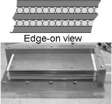
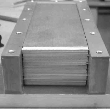
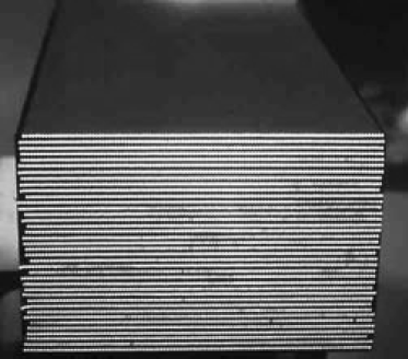
The concept of plate / ribbon stacking is shown in the upper half of Fig. 2a. Assembly consisted of alternately stacking tungsten plates and fiber ribbons in a jig, the lower half of Fig. 2a and also Fig. 2b. The fiber ends were aligned with the right-side jig face, while the tungsten plates were positioned roughly 0.5 cm from this jig edge. After the stack was completed, Fig. 2b, a top and side plate were attached, establishing the final fixed dimension. The assembly was then turned upward and 1266 Stycast epoxy was poured into the assembly in a manner to ensure a careful and uniform distribution among all layers. A vacuum was pulled from the bottom through one of the tubes seen in Fig. 2a. Once the glue was drawn through the stack, being visible in the tube, the tubing was removed and the two drainage holes on the right-side jig face were plugged. Since the fibers extended beyond the tungsten plates on both sides, an epoxy-fiber solid appendage was formed, which could then be machined easily to a smooth and polished surface, see Fig. 2c. The final array, illuminated by a standard lamp, is shown in Fig. 2d.
3 Experimental Tests and Simulations
The W/SciFi detector was first tested at electron energies of 0.140, 0.245, and 0.300 GeV at the piM1 beamline at the Paul Scherrer Institut (PSI), and later at the more relevant energies from 1.5 to 3.5 GeV at the Meson Test Beam at Fermilab (FNAL). The focus of the test beam measurements was on calorimeter linearity and energy resolution. While neither beamline was optimized to provide a small momentum resolution or spot size, sufficient performance information was obtained to compare measurement to GEANT-4 based Monte Carlo simulations.
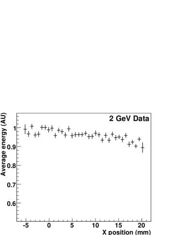
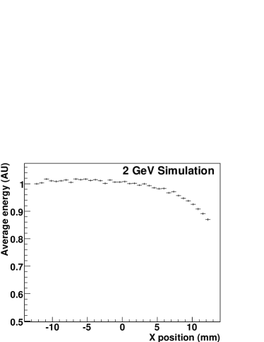
At FNAL, a broad negative beam was transported through a Cherenkov counter (used to identify electrons), scintillator paddles, and several multi-wire proportional chambers. Finally, the beam would impact on the front faces of the W/SciFi prototype and two cm2 Pb/SciFi “reference” detectors (each longer than 20 in depth). Because the W/SciFi detector uses green fibers, it was read out using a Hamamatsu R7899MOD (Extended Green Photocathode, 1-inch diameter, Prismatic Window) photomultiplier tube. Placed at each side of the tungsten detector, the Pb/SciFi calorimeters were coupled to standard 2-inch bialkali PMTs. These detectors were used to provide shower containment for the tungsten module, as well as to provide reference energy resolution measurements under the same beam conditions. Each of the three calorimeters was wrapped in black electrical tape to keep them individually lighttight. The beamline wire chambers permitted horizontal and vertical impact resolution with approximately 3-mm precision. The incident default angle for both data taking and Monte Carlo was 5 degrees. Figure 3 shows the average energy in a module versus beam impact position over a 25 mm centered impact range. The dip in the average at larger horizontal impact values (for both data and Monte Carlo) is due to leakage for incomplete shower containment because the beam enters at a 5-degree impact angle.
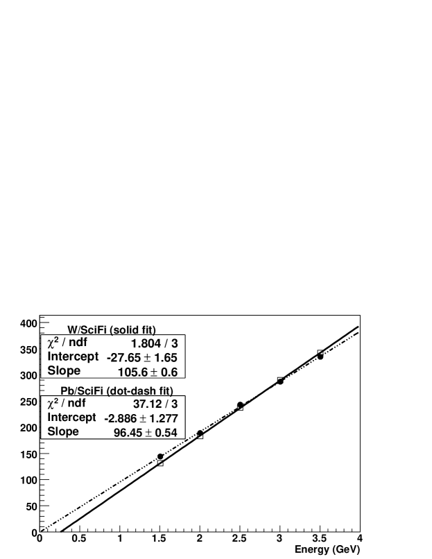
An energy sweep under the conditions that the beam impacted well within the boundary of either the W/SciFi or one of the Pb/SciFi detectors leads to the linearity plot shown in Fig. 4. While the lead detector has a vertical intercept consistent with zero, the tungsten detector has a negative offset of 28 channels. This offset was originally unnoticed, and is presumed to be tied to a small positive dc bias integrated over a large ADC gate. The 28-channel offset is corrected for in the analysis that follows.
At PSI, a similar detector setup was used at the piM1 beamline. Again, a broad negative beam was transported to the detectors. Small scintillator paddles were used to trigger beam impact on the W/SciFi within the edge boundaries. The beam consisted of a small fraction of electrons as compared to pions and muons. Timing with respect to the machine 50 MHz RF was used to select the electron signal and out-of-time sideband subtraction was also used to remove unwanted background.
3.1 Energy Resolution
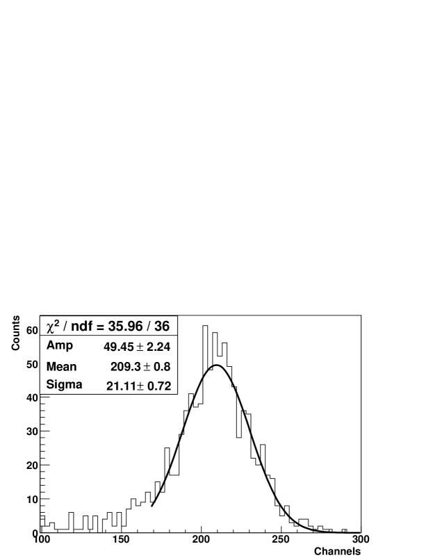
The typical energy threshold for including events is 2 GeV; positrons are only accepted above this threshold. A resolution of (defined as for a simple Gaussian fit) would give an acceptable performance for this threshold in a future experiment. The response of the prototype tungsten detector is shown in Fig. 5 for 2 GeV electrons impacting at 5 degrees with respect to the fiber axis. An entrance cut is made using the wire chamber information to select the central 15 mm by 30 mm (width by height) of the 40- by 60-mm detector face. Even with no corrections for leakage into side detectors, or adjustments for sub-optimal light collection, or beam momentum uncertainty, (see below) the resolution at meets the experimental goal.
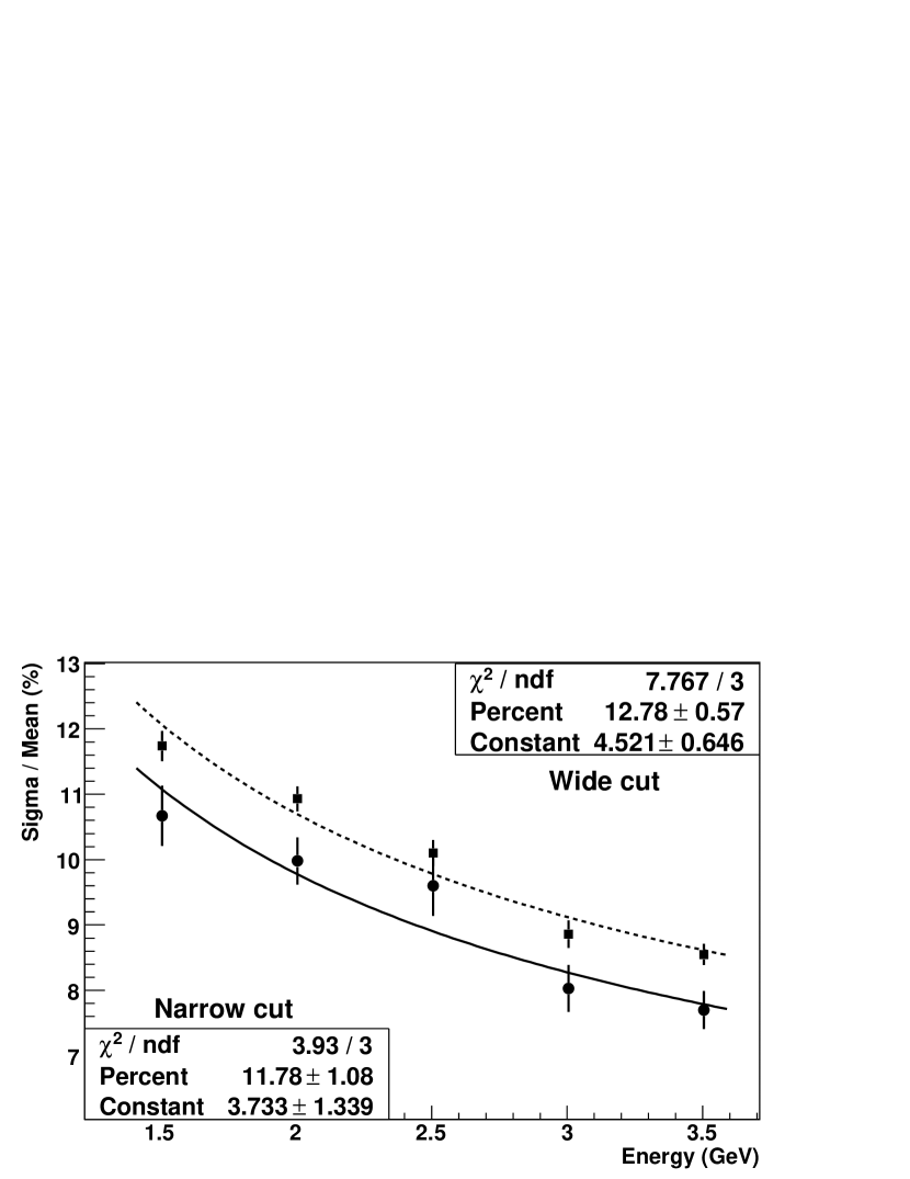
Our goal is to understand the intrinsic sampling resolution of this detector and compare it to simulation. While the stochastic term is mainly determined by the sampling fluctuations intrinsic to the active-to-absorber material ratio and the effective layer thickness, additional contributions enter from photo-statistics. A contribution exists from photo-statistics, because the measured photoelectron (pe) yield is 400 pe/GeV. This is a smaller light yield than we would expect had the lightguide been better matched in area to the photomultiplier tube and if blue fibers were used instead of green (higher quantum efficiency). Two factors that scale with energy contribute to energy degradation—the transverse leakage, and the momentum uncertainty of the test beam. The leakage can be explored with data cuts and simulation; the is unknown but estimated to be a few percent. In Fig. 6, we plot the FNAL data fit to
| (1) |
Here represents the intrinsic sampling term, is the photo-statistics uncertainty, and is a linear term. The term is fixed at and is given in GeV. The upper curve is a fit based on data where a 25 mm “wide cut” in the entrance width of the beam was used, while the lower curve is a fit based on a 5 mm “narrow cut.” The change affects both the sampling and the constant term as they are not easily separable, given the statistics. The narrow cut result minimizes, but does not eliminate, the leakage, resulting in and for the stochastic and constant terms, respectively. The same entrance cuts could not be made with the three low-energy PSI data points owing to the different setup, but the fit results did not change when those points, which are dominated by the stochastic terms, were included.
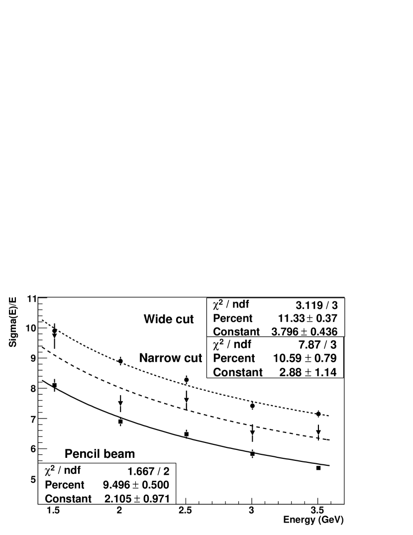
The sampling fluctuation component can be predicted using a complete GEANT-4 model [11]. A plot of this resolution versus energy for simulated electrons impacting on the module center at a 5-degree angle is shown in Fig. 7. Three curves are presented representing a high-statistics “pencil beam” with a 1 mm spot size in both dimensions, as well a separate simulation with data-like cuts of 5- and 25-mm entrance widths, which match the narrow and wide definitions for the data. The most appropriate comparison to data is the narrow cut, which yields and for the stochastic and constant terms, respectively. The term is representative of the leakage, since no uncertainty contributes for Monte Carlo. If we deconvolute the leakage contribution from the term in the data, a of is implied, which is not unreasonable.
The simulation is, not surprisingly, somewhat better than the actual prototype— vs. . Detector construction imperfections can contribute, as would non-uniform light collection in the guide. However, to explore this comparison more completely will require a larger test module with improved readout and a better controlled test beam environment. Note, that we carefully checked the GEANT-4 cut parameters, but found no dependence on them that altered our results.
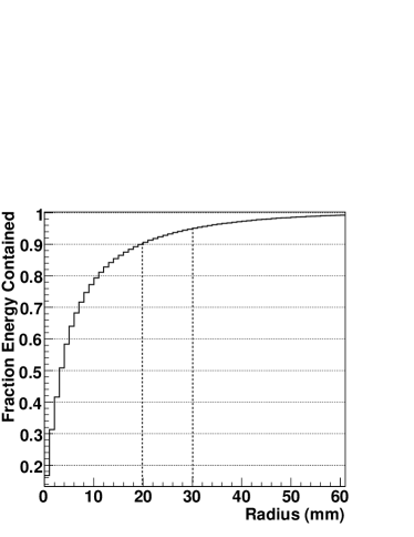
3.2 Transverse and Longitudinal Profile
A GEANT-4 model was used to study the transverse and longitudinal shower profiles and compare to the standard analytical calculations [8]. Energy containment as a function of transverse distance for a pencil beam is shown in Fig. 8a. The vertical dotted lines indicate the radii of and containment, respectively. The line corresponds to the simulated Molière radius of approximately cm, which is greater than the 1.73 cm expectation from the calculation. The depth of the longitudinal profile maximum—shower max—increases proportional to ; typically , where is the shower maximum. The profiles of energy deposit versus depth for a range of incident energies were fit to determine the shower maxima. Figure 8b shows a plot of shower max versus energy. A linear relation is evident with the energy axis plotted on a log scale. The slope of the fit corresponds to the simulated radiation length, determined to be cm, which is also somewhat larger than the analytical expectation of 0.69 cm.

3.3 Angle of Impact on Layered Sampling Calorimeters
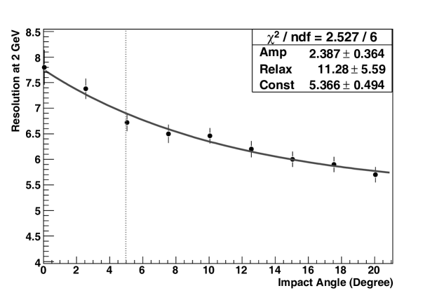
It is possible to orient a lead- or tungsten-scintillating calorimeter at near head-on impact with respect to the incoming beam. This permits readout at the rear, as well as near arbitrary transverse segmentation. As zero degree orientation is approached, channeling—long particle paths through the low- active material—can occur without showering, which reduces the resolution and the containment fraction. The layers appear “thicker” at shallow angles since the secondaries in the original shower development largely retain the incoming electron direction (only at the end are they more isotropic). For , the impact angle on a calorimeter face varies from a few degrees to degrees for positrons of interest. It is possible to tilt the calorimeter outward so that 5 degrees represents a minimum striking angle, which is the motivation for this impact choice in many of the studies reported here. The expected improvement in resolution at larger angles was simulated using 2 GeV incoming electrons spread uniformly over one tungsten plate and fiber layer. The result is shown in Fig. 9. A parameterization is given by a function of the form: , where represents a relaxation term and the constant term is the resolution at 90-degrees.
While the narrow width of the module and limited statistics prevented an exhaustive test, a comparison at 2 GeV was made using beam data at 5 and 15-degree impact and with a 15-mm-wide by 20-mm high entrance cut centered on the module front face. The fractional resolution improved in the data by , which is similar to the reduction found in the Monte Carlo for the same angular impact change (see Fig. 9).
3.4 Resolution versus layer thickness
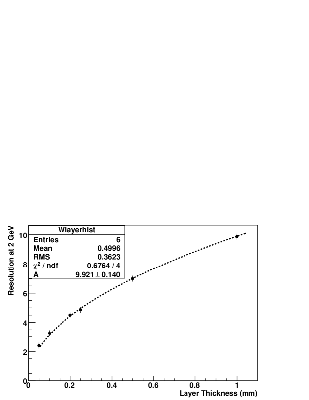
Resolution improves for smaller effective layer thicknesses when fixing the absorber-to-active material ratio. This was one of the driving motivations to develop scintillating-fiber-based calorimeters [2]. Commercial vendors have improved fiber production quality and delivery options. Since there is a larger range in sizes for calorimeter components, it is now worth carefully evaluating the resolution-to-cost ratio for a given application. In Fig. 10, we show a simulation for 5-degree impact 2-GeV electrons versus the thickness of the fiber ribbons, while maintaining a constant 50:50 fiber/epoxy:tungsten (volume) ratio. The overall module width is kept fixed at 40 mm and the electron impact is centered across a horizontal width of twice the layer thickness. The figure includes a simple fit to , a good model that follows expectations for sampling scaling with layer thickness . Detector costs typically scale with overall fiber length and plate number (linearly and not by volume, for both product purchase and assembly considerations). Resolution degradation terms (typically constant terms) increase with detector imperfections, such as material tolerances and construction imperfections. As is evident from Fig. 10, the intrinsic resolution only improves as the square root of the thickness. Therefore, it is a matter of the demands of the application and a delicate balance of constant terms and photo-statistics limitations to determine where to set the layer thicknesses. For our application, the 0.5-mm layer thickness is close to ideal, but with improved light collection, perfected assembly procedures, and strict mechanical tolerance specifications, one could aim for a factor of 2 reduction in layer thickness. However, fibers would have to be carefully tested for attenuation losses at such a small diameter.
4 Summary
A dense and fast electromagnetic calorimeter prototype has been described. With 0.5-mm layers of tungsten plates and scintillating fiber ribbons, it promises acceptable resolution compared to the Pb/SciFi detectors on which the concept is based, but at a calculated radiation length of only 0.69 cm. With fine-tuning of the W/SciFi ratio or the layer thickness, resolution can be adjusted to meet application demand. The straight-forward assembly procedure can be scaled for modules of different widths and lengths. The small transverse shower dimensions ( cm) is appropriate for use with small-area PMTs or with new SiPMs.
References
- [1] P. Sonderegger, Nucl. Instr. and Meth. A257, 523 (1987); H. Burmeister et al., Nucl. Instr. and Meth. 225, 530 (1984)
- [2] D.W. Hertzog et al., Nucl. Instr. and Meth. A294 (1990) 446.
- [3] S.A. Sedykh et al., Nucl. Instrum. Meth. A455, 346 (2000).
- [4] M. Adinolfi et al., Nucl. Instr. and Meth. A482 (2002) 364.
- [5] The Collaboration: G.W. Bennett et al., Phys. Rev. D 73 (2006) 72003.
- [6] G.T. Danby, et al., Nucl. Instr. and Methods Phys. Res. A 457, 151-174 (2001).
- [7] For example, Experiment E969 at BNL A Experiment to ppm Precision, R.M. Carey, et al, D.W. Hertzog and B.L Roberts, co-spokesmen; (2004).
- [8] For example, see C. Fabjan, “Calorimetry in high-energy physics”, Experimental Techniques in High-Energy Nuclear and Particle Physics, 2nd Ed., World Scientific Publishing Co., T. Ferbel, Ed., (1991), 257.
- [9] Marketech International, 4750 Magnolia Street, Port Townsend, WA 98368.
- [10] Saint-Gobain Crystals and Detectors, 12345 Kinsman Road, Newbury, OH 44065.
- [11] S. Agostinelli, et al., Nucl. Instrum. Meth. A 506, 250 (2003).