Damping of a nanomechanical oscillator strongly coupled to a quantum dot
Abstract
We present theoretical and experimental results on the mechanical damping of an atomic force microscope cantilever strongly coupled to a self-assembled InAs quantum dot. When the cantilever oscillation amplitude is large, its motion dominates the charge dynamics of the dot which in turn leads to nonlinear, amplitude-dependent damping of the cantilever. We observe highly asymmetric lineshapes of Coulomb blockade peaks in the damping that reflect the degeneracy of energy levels on the dot, in excellent agreement with our strong coupling theory. Furthermore, we predict that excited state spectroscopy is possible by studying the damping versus oscillation amplitude, in analogy to varying the amplitude of an ac gate voltage.
Coupling a nanomechanical object to quantum electronics provides a system that can be used to probe both the mechanics and the electronics with extreme sensitivity. It has been predicted that the electronics may be used to measure the quantum nature of the mechanical object Armour et al. (2002), and the reverse—using the mechanics to measure the quantum nature of mesoscopic electronics—was recently demonstrated with superconducting qubits LaHaye et al. (2009). Electromechanical systems that have attracted considerable attention recently include quantum shuttles Koenig et al. (2008), and mechanics coupled to single electron transistors Knobel and Cleland (2003); Naik et al. (2006) or tunnel junctions Flowers-Jacobs et al. (2007); Poggio et al. (2008). In most systems studied both experimentally and theoretically, the interaction between the electronic and mechanical components is weak.
In this paper we study strong coupling effects, both theoretically and experimentally, in an electromechanical system consisting of a quantum dot capacitively coupled to an atomic force microscope (AFM) cantilever. Electrons tunneling on and off the dot effectively damp the cantilever, and this damping exhibits Coulomb blockade peaks as a function of bias voltage similar to those well known in the dot conductance, even in the limit of weak coupling Woodside and McEuen (2002); Zhu et al. (2008); Cockins et al. . It has long been predicted that level degeneracy on the dot leads to lineshape asymmetry of Coulomb blockade peaks in the conductance Beenakker (1991). Recently, we observed corresponding temperature-dependent peak shifts in the damping at weak coupling Cockins et al. , but the lineshape asymmetry was far too small to be measured before now. However, by driving the cantilever to large oscillation amplitudes we enter a regime of strong coupling where its motion strongly modifies the tunneling rates on and off the dot, and leads to a dramatic enhancement of the lineshape asymmetry. This enhancement is much greater than expected from simply extrapolating the weak coupling theory; it is a non-adiabatic effect that stems from the similarity of timescales for dynamics of the cantilever and the dot. Furthermore, we predict that by measuring the damping versus bias voltage and oscillation amplitude, strong coupling provides a means to perform excited state spectroscopy on the dot. Note that very different strong coupling effects unrelated to degeneracy were recently reported for a driven carbon nanotube coupled to an embedded dot Steele et al. (2009); Lassagne et al. (2009).
Our results show that AFM operated at large oscillation amplitudes may be used to study degeneracy and level spacing, so-called shell structure, in quantum electronic systems. The particular systems studied here, self-assembled quantum dots, are candidates for applications such as quantum information processing, and measuring their shell structure has attracted extensive research effort Drexler et al. (1994); Miller et al. (1997); Raymond et al. (2004); Jung et al. (2005). Our technique allows the level degeneracy to be read off from a single sweep of damping versus bias voltage, and offers the practical advantage that non-contact AFM is a way to address many dots one by one without the need for electrical contacts.
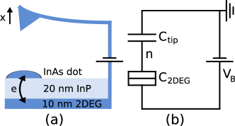
Setup.—The mechanical oscillator is an AFM cantilever with resonant frequency kHz, spring constant N/m, and intrinsic quality factor of typically . It is driven on resonance in self-oscillation mode at constant amplitude and mean tip-sample gap of 19 nm Cockins et al. . The cantilever is coated with a 10 nm Ti adhesion layer and a 20 nm Pt layer to ensure good electrical conductivity at low temperature. All data in this paper was collected at 5K. The sample is grown by chemical beam epitaxy, with the relevant features being uncapped InAs dots on top of a 20 nm InP tunnel barrier and a 10 nm InGaAs two-dimensional electron gas (2DEG) which acts as a back electrode. For full sample details see Ref. Cockins et al. . The bias voltage is applied to the 2DEG layer, with the cantilever electrically grounded (see Fig. 1). The potential drop between the 2DEG and the dot is , where is extracted from the experiment and is the total dot capacitance. The dot-cantilever coupling arises through , which depends on the tip position . Electrons tunnel between the 2DEG and the dot when is sufficient to lift Coulomb blockade, while tunneling between the dot and cantilever is negligible due to the relatively large distance between them. The fluctuating charge on the dot results in both damping and a resonance frequency shift of the cantilever; in the limit of weak coupling these are well described by linear response Clerk and Bennett (2005). Here we focus on the damping, which is provided in addition to the frequency shift by a phase-locked loop frequency detector and automatic gain controller Cockins et al. .
Model.—Provided the cantilever motion is small compared to the the tip-dot separation, we can assume that depends linearly on and write the charging Hamiltonian of the dot as Stomp et al. (2005)
| (1) |
where is the number of electrons on the dot, is the dimensionless gate voltage (or control charge), and is the charging energy neg . is the oscillator-independent part of , and , is a constant electrostatic modification of the oscillator potential. Interactions between the dot and oscillator are described by the final term with coupling strength . We stress that the strong coupling effects discussed here occur despite remaining linear in ; they arise from the -dependent tunneling rates discussed below. From Eq. (1) we see that the dot charge exerts a force on the oscillator; conversely, the oscillator position changes the energy cost of adding or removing an electron on the dot.
We focus on the bias range where 0 or 1 extra electrons reside on the dot, with other charge states prohibited by Coulomb blockade; it is simple to generalize this to the case of or electrons on the dot. The tunneling rates between the dot and back electrode are calculated from Fermi’s golden rule accounting for the shell structure of the dot, i.e. the degeneracy of single particle levels. For a shell of degeneracy occupied by electrons, there are ways to add an electron, and once it has been added there are ways to remove it. The extra energy with 1 electron on the dot (i.e. the chemical potential difference between the dot and back electrode) is , which is modulated by through the coupling. In the classical oscillator limit, Qua ; Clerk and Girvin (2004), this results in -dependent rates () to add (remove) an electron,
| (2) | ||||
| (3) |
where is the tunneling rate to a single particle state and is the Fermi function. The asymmetry between adding and removing electrons is the root of the asymmetry in Coulomb blockade peaks Beenakker (1991).
We describe the coupled system using a master equation for the charge on the dot combined with a Fokker-Planck equation for the phase space distribution of the oscillator Armour et al. (2004); Doiron et al. (2006). The central objects are the probabilities and to find the oscillator at position and velocity with 0 or 1 extra electrons on the dot; these satisfy master equations with -dependent rates,
| (4) | ||||
| (5) |
where describes the evolution of a driven, damped harmonic oscillator and is the equilibrium position with electrons on the dot. The damping coefficient is intrinsic to the oscillator without coupling to the dot, and is the external driving force.
While it is straightforward to simulate the master equations directly, we gain further insight by focusing on the simpler dynamics of system averages. Following Ref. Rodrigues et al. (2007), we make the approximation that averages of products may be factorized into products of averages. While we lose correlations contained in Eqs. (4) and (5), we find from comparison with full simulations that the asymmetric damping lineshape is still captured. Within this approximation we use Eqs. (4) and (5) to obtain coupled equations for the average quantities,
| (6) | ||||
| (7) | ||||
| (8) |
We seek a solution where the cantilever oscillates at constant amplitude , replicating the experiment, such that . Ignoring the frequency shift due to tunneling (since ) and assuming that the total damping is small (, justified self-consistently), we find that the effective, amplitude-dependent damping due to tunneling is given by Rodrigues et al. (2007)
| (9) |
and obtain constant amplitude oscillations for drive . Eq. (9) explicitly connects the damping to the time-varying dot charge, , specifically the part that is out of phase with the cantilever position . Note that damping arises even in the case of weak coupling, and is measurable using an oscillator of sufficiently high quality factor Cockins et al. , but Eq. (9) remains valid at strong coupling. It also reduces our calculation of to solving Eq. (8) for numerically (inserting ), a much easier task than directly simulating Eqs. (4) and (5).

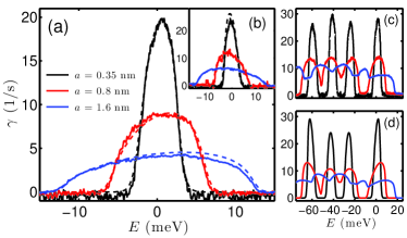
Coulomb blockade peaks in the damping occur at charge degeneracy points, where the dot energy is equal with either 0 or 1 electrons and charge fluctuations are maximal Cockins et al. . Fig. 2(a) shows the first damping peak versus gate voltage for several oscillation amplitudes, calculated both using Eq. (9) and from direct simulation of Eqs. (4) and (5) following the approach of Ref. Doiron et al. (2006). We assume the level structure of a cylindrically symmetric dot, which includes a 2-fold degenerate shell and a 4-fold degenerate shell Kouwenhoven et al. (2001). The simulated damping is well described by linear response (green dashed) at weak coupling; note that even this peak is very slightly asymmetric as expected. As the oscillation amplitude is increased, the peak becomes broadened and highly asymmetric. The enhanced asymmetry at strong coupling is completey missed in an adiabatic approximation, where one assumes that the oscillator motion is much slower than tunneling (see Fig. 2(b)). This is not surprising: since , the cantilever can move significantly before an electron tunnels on or off the dot. On the other hand, the damping calculated from our semi-analytic theory (see Eq. (9)) agrees very well with the full simulation, so we use it to understand why the lineshape in the damping is so highly asymmetric at strong coupling.
Asymmetric lineshape.—The asymmetric lineshape of Coulomb blockade peaks is a result of the asymmetry between adding or removing electrons to or from a degenerate shell on the dot (cf. Eqs. (2) and (3)). Consider the bias points c and e on either side of the peak in Fig. 2(a), equal distances from its center such that the largest amplitude oscillator motion (broadest peak) is just large enough to swing onto the charge degeneracy point. One might guess that that a tunnel event near is equally likely in both cases, but in fact tunneling is twice as likely to occur when starting from point e, where the dot is initially empty. This is because the rate to tunnel onto the dot near the charge degeneracy point is (for the first peak in the 2-fold degenerate shell), while the rate to tunnel off is only . The asymmetry is apparent in the time dependence of at three bias points, shown in Fig. 2(c-e). Tunneling is more likely starting from point e, and this leads to increased damping. Conversely, the situation is reversed in the second Coulomb blockade peak where there is only one way to add an electron to the half full shell but two ways to remove one once it is full. Thus, for large amplitudes when the asymmetry is visible, the lineshape provides a way to read off the shell degeneracy from a single sweep: each peak is skewed away from the center of its shell.
While a similar argument leads to a very slightly asymmetric lineshape at weak coupling, the asymmetry at strong coupling is much greater than we would expect by extrapolation. This is because, for sufficiently strong coupling , the change in gate voltage due to the oscillator motion is greater than the thermal broadening from the Fermi distribution of electrons in the back electrode. In other words, the oscillator motion dominates over temperature, . When this is satisfied, the harmonic distribution of the oscillator position , peaked at the turning points of its motion, causes the most asymmetric tunneling rates, at the oscillator extrema, to become especially important. The extra weighting of the most asymmetric rates leads to the dramatically asymmetric lineshape at strong coupling.
Finally in our discussion of the lineshape asymmetry, we point out the importance of relative timescales. For a slow oscillator, , the adiabatic approximation is valid since the dot charge quickly equilibrates in response to the slow cantilever motion. In this case the damping is simply given by a weighted average of the linear response result taken over the oscillating gate voltage, and the lineshape asymmetry remains immeasurably small (see Fig. 2(b)). In the opposite limit, , the dot charge cannot respond to the rapid oscillator motion and damping is suppressed. This can be seen from Eq. (9): for , is roughly constant over one oscillator period and the damping becomes vanishingly small. The case that we have focussed on and measured is , where the interplay between the oscillation and tunneling timescales leads to maximal and highly asymmetric damping.
Measured Damping.—The experimentally measured cantilever damping is compared with theory in Fig. 3. In (a) and (b) we fit the first two Coulomb blockade peaks for three oscillation amplitudes (given in the legend) using Eq. (9). For each charge degeneracy point, we used a single fit parameter to fit the peak at all three amplitudes, obtaining the values given in the caption. These are in good agreement with the values obtained from our weak coupling experiment on the same dot Cockins et al. . We took the charging energy meV and lever arm extracted at weak coupling. In principle these parameters may also be found by fitting the strong coupling data directly, but we took advantage of our weak coupling results as a calibration and kept them fixed. Lastly, we point out that the cantilever damping is dominated by tunneling: here we find a peak value of up to , and at weak coupling (where the cantilever motion is small and does not move off the charge degeneracy point) we measured as high as Cockins et al. .
In Fig. 3(c) and (d) we show the measured and theoretical damping versus bias over the entire shell. This is calculated by a straightforward extension of our derivation of Eq. (9) to allow up to four electrons to occupy the 4-fold degenerate shell. We find good qualitative agreement even in the crude approximation of constant charging energy, and using single values of and over the entire shell Aan . We took meV for the shell (estimated from the peak spacing), and roughly aligned the peaks by adjusting the shell level splitting phenomenologically. Once this was done, a single set of parameters was used to produce the damping spectra at all three amplitudes. Most importantly, in both theory and experiment the four peaks in the -shell become five at large amplitudes, with peaks emerging directly between the charge degeneracy points. This is completely consistent with our simple theory: at large amplitudes, the oscillator distribution is peaked at its extrema and contributions to tunneling are most important there. Thus, for amplitudes such that , the tunneling is maximal when the bias voltage is at the midpoint between two degeneracy points.
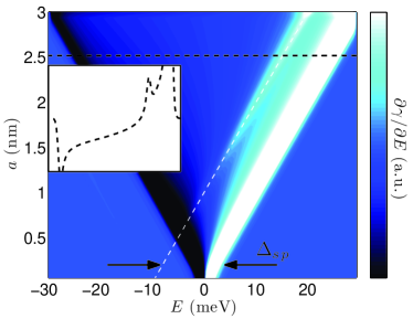
Excited state spectroscopy.—Theoretically, our setup can be used to perform level spectroscopy on the dot, for example to measure the energy difference between the and shells, . The oscillator is directly analogous to an ac gate voltage on the dot Elzerman et al. (2004). In the same way, when the oscillator motion is large enough to allow transitions to multiple energy levels on the dot, the effective tunneling rate increases as does the damping. This is possible when the change in energy due to the oscillator is equal to the energy spacing, or . At large amplitudes we expect a jump in at the bias voltage where . This leads to a peak in that forms a line when plotted versus and , as seen in Fig. 4. Measuring the slope and intercept of this line in experiment would directly provide and .
Conclusions.—We have shown that the oscillation amplitude is a useful new axis to exploit in using mechanical measurements to probe quantum electronic systems. We demonstrated our technique using self-assembled quantum dots; however, its implications extend to other quantum electronic systems that can be placed on an insulating surface with a back electrode. In particular, it should be possible to use AFM to study the level structure of single molecules. Due to the large spacing between energy levels, these may be studied at relatively high temperatures using further increased oscillation amplitudes.
This work was supported by NSERC, FQRNT and CIFAR.
References
- Armour et al. (2002) A. D. Armour, M. P. Blencowe, and K. C. Schwab, Phys. Rev. Lett. 88, 148301 (2002).
- LaHaye et al. (2009) M. D. LaHaye, J. Suh, P. M. Echternach, K. C. Schwab, and M. L. Roukes, Nature 459, 960 (2009).
- Koenig et al. (2008) D. R. Koenig, E. M. Weig, and J. P. Kotthaus, Nat. Nano. 3, 482 (2008).
- Knobel and Cleland (2003) R. G. Knobel and A. N. Cleland, Nature 424, 291 (2003).
- Naik et al. (2006) A. Naik, O. Buu, M. D. LaHaye, A. D. Armour, A. A. Clerk, M. P. Blencowe, and K. C. Schwab, Nature 443, 193 (2006).
- Flowers-Jacobs et al. (2007) N. E. Flowers-Jacobs, D. R. Schmidt, and K. W. Lehnert, Phys. Rev. Lett. 98, 096804 (2007).
- Poggio et al. (2008) M. Poggio, M. P. Jura, C. L. Degen, M. A. Topinka, H. J. Mamin, D. Goldhaber-Gordon, and D. Rugar, Nat. Phys. 4, 635 (2008).
- Woodside and McEuen (2002) M. T. Woodside and P. L. McEuen, Science 296, 1098 (2002).
- Zhu et al. (2008) J. Zhu, M. Brink, and P. L. McEuen, Nano Letters 8, 2399 (2008).
- (10) L. Cockins, Y. Miyahara, S. D. Bennett, A. A. Clerk, and P. Grütter, arXiv:0910.0005.
- Beenakker (1991) C. W. J. Beenakker, Phys. Rev. B 44, 1646 (1991).
- Steele et al. (2009) G. A. Steele, A. K. Huttel, B. Witkamp, M. Poot, H. B. Meerwaldt, L. P. Kouwenhoven, and H. S. J. van der Zant, Science 325, 1103 (2009).
- Lassagne et al. (2009) B. Lassagne, Y. Tarakanov, J. Kinaret, D. Garcia-Sanchez, and A. Bachtold, Science 325, 1107 (2009).
- Drexler et al. (1994) H. Drexler, D. Leonard, W. Hansen, J. P. Kotthaus, and P. M. Petroff, Phys. Rev. Lett. 73, 2252 (1994).
- Miller et al. (1997) B. T. Miller, W. Hansen, S. Manus, R. J. Luyken, A. Lorke, J. P. Kotthaus, S. Huant, G. Medeiros-Ribeiro, and P. M. Petroff, Phys. Rev. B 56, 6764 (1997).
- Raymond et al. (2004) S. Raymond, S. Studenikin, A. Sachrajda, Z. Wasilewski, S. J. Cheng, W. Sheng, P. Hawrylak, A. Babinski, M. Potemski, G. Ortner, et al., Phys. Rev. Lett. 92, 187402 (2004).
- Jung et al. (2005) M. Jung, T. Machida, K. Hirakawa, S. Komiyama, T. Nakaoka, S. Ishida, and Y. Arakawa, Appl. Phys. Lett. 87, 203109 (2005).
- Clerk and Bennett (2005) A. A. Clerk and S. Bennett, New J. Phys. 7, 235 (2005).
- Stomp et al. (2005) R. Stomp, Y. Miyahara, S. Schaer, Q. Sun, H. Guo, P. Grutter, S. Studenikin, P. Poole, and A. Sachrajda, Phys. Rev. Lett. 94, 056802 (2005).
- (20) We neglect the term coupling to since it is higher order in .
- (21) Quantum corrections to the rates occur when (see Ref. Clerk and Girvin (2004)), but these are negligible here.
- Clerk and Girvin (2004) A. A. Clerk and S. M. Girvin, Phys. Rev. B 70, 121303(R) (2004).
- Armour et al. (2004) A. D. Armour, M. P. Blencowe, and Y. Zhang, Phys. Rev. B 69, 125313 (2004).
- Doiron et al. (2006) C. B. Doiron, W. Belzig, and C. Bruder, Phys. Rev. B 74, 205336 (2006).
- Rodrigues et al. (2007) D. A. Rodrigues, J. Imbers, T. J. Harvey, and A. D. Armour, New J. Phys. 9, 84 (2007).
- Kouwenhoven et al. (2001) L. P. Kouwenhoven, D. G. Austing, and S. Tarucha, Rep. Prog. Phys. 64, 701 (2001).
- (27) Both and are bias dependent over the large voltage range of the shell.
- Elzerman et al. (2004) J. M. Elzerman, R. Hanson, L. H. W. van Beveren, L. M. K. Vandersypen, and L. P. Kouwenhoven, Appl. Phys. Lett. 84, 4617 (2004).