A scalable Bose-Einstein condensate Sagnac interferometer in a linear trap
Abstract
We demonstrate a two-dimensional atom interferometer in a harmonic magnetic waveguide using a Bose-Einstein condensate. Such an interferometer could measure rotation using the Sagnac effect. Compared to free space interferometers, larger interactions times and enclosed areas can in principle be achieved, since the atoms are not in free fall. In this implementation, we induce the atoms to oscillate along one direction by displacing the trap center. We then split and recombine the atoms along an orthogonal direction, using an off-resonant optical standing wave. We enclose a maximum effective area of 0.1 mm2, limited by fluctuations in the initial velocity and the coherence time of the interferometer. We argue that this arrangement is scalable to enclose larger areas by increasing the coherence time and then making repeated loops.
pacs:
03.75.Dg, 37.25.kAtom interferometry has proven useful for a variety of precision measurements, notably including rotations Berman (1997); Gustavson et al. (2000); Durfee et al. (2006). Through the Sagnac effect Sagnac (1913), an interferometer that encloses area on a platform rotating at rate develops a phase proportional to the product of and . Greater sensitivity is therefore obtained by increasing the area. The best atom gyroscope at present uses a thermal atomic beam in a 2-m-long Mach-Zehner configuration, with an enclosed area of 30 mm2 Durfee et al. (2006). It exhibits impressive performance, but the considerable length of the device limits potential applications.
A possible resolution to this problem is guided-wave atom interferometry, in which the atoms are continuously confined by optical or magnetic fields. The guiding fields can direct the atoms along more compact trajectories than possible in free space. For instance, an enclosed area comparable to the above could be obtained by passing the atoms around a circular loop of only 6-mm diameter. In addition, the confining potential supports the atoms against gravity, permitting longer interaction times. A significant effort is underway to develop such devices Sauer et al. (2001); Wu et al. (2004); Gupta et al. (2005); Wu et al. (2007); Jo et al. (2007); Griffin et al. (2008), but to date, only relatively small enclosed areas have been demonstrated. We present here a design that we argue has good potential to scale to large area and take advantage of the benefits of the guided-wave approach.
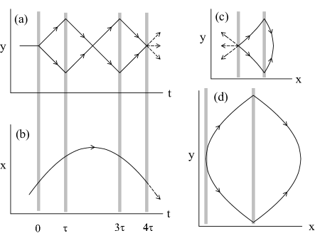
The design is based on a linear guided-wave interferometer Garcia et al. (2006). A Bose-Einstein condensate is produced in a harmonic trap. One axis () of the trap is weakly confining, and an off-resonant standing wave laser passing along that axis is used to split, manipulate, and recombine the atomic wave packets. The trajectory is shown in Fig. 1(a). Note that a reciprocal trajectory is used, in which both packets traverse identical paths. This causes static perturbations from the confining potential to largely cancel Burke et al. (2008). To generate an enclosed area, we operate the interferometer with atoms that are also moving in the transverse () direction. In that direction, the atoms undergo harmonic oscillation. The laser pulses are timed so that a turning point in occurs at the midpoint of the interferometer, as shown in Fig. 1(b). The trajectory in the -plane is shown in Fig. 1(c), and is clearly both area-enclosing and reciprocal.
Our technique is similar to that of Wu et al. Wu et al. (2007), but there the transverse motion is achieved by translating the guide itself rather than by excitation within in the guide. The primary difference here is our use of a Bose-Einstein condensate, compared to laser-cooled atoms. This makes the moving guide approach challenging, since the guide would need to be tightly confining to ensure the atoms followed it adiabatically. For a condensate, tight confinement increases interaction effects that can spoil the interference.
Using a condensate does, however, allow a higher degree of control. When applied to a thermal sample, the standing-wave laser pulses produce many different interfering paths with differing enclosed areas. These parallel loops produce a complicated output state, from which a Sagnac signal must be reconstructed. Wu et al. demonstrate how this can be achieved (see also Tonyushkin and Prentiss (2008)), but it is not yet clear whether their methods can be extended to the accuracy needed for precision measurements. In addition, the large range of initial atomic velocities makes the interferometer imperfectly reciprocal and thus more sensitive to errors. In contrast, the low momentum spread of a condensate permits our interferometer to be operated with a single reciprocal trajectory to a high degree of accuracy.
The linear interferometer on which our method is based has been described previously Garcia et al. (2006). To start, a Bose-Einstein condensate of 87Rb atoms is prepared in the hyperfine state and held in a harmonic time-orbiting potential (TOP) trap. Confinement is intentionally weak, with atom oscillation frequencies Hz. Weak confinement in combination with support against gravity is achieved by modulating the magnetic quadrupole field in phase with the rotating bias field of the TOP trap Reeves et al. (2005).
We excite the transverse motion by suddenly changing the phase difference between the bias and quadrupole fields, which shifts the trap minimum along . The displacement is not purely transverse, so in general oscillations are induced in all three directions. However, at a suitable time later the phase is switched back, causing the oscillation to be enhanced while the oscillation is reduced. Typical values of the oscillation amplitudes are mm and residual amplitudes of m in the other directions.
The motion along is controlled by a standing-wave laser at a wavelength nm, 70 GHz blue of the laser-cooling transition. The laser couples states of momentum where and is an integer. The corresponding velocity is 1.2 cm/s. In particular, the interferometer uses the beam-splitting transition and the reflection transition , both of which can be implemented with high precision Wu et al. (2005); Hughes et al. (2007). We use a 1-cm diameter laser beam to encompass the range of transverse locations needed for the pulses.
To create the interferometer, a splitting pulse is applied at time , reflections at times and , and a splitting pulse again at . In general, the output consists of three momentum states, . The populations of the states depends on the interferometer phase , with for visibility . We vary in a controlled way by adjusting the frequency of the coupling laser before the final splitting operation, which has the effect of shifting the standing wave along . This permits an interference curve to be mapped out and the visibility determined. With no transverse excitation, interference is observed for total times up to 72 ms. This is limited by phase gradients imposed by the non-uniform potential along the guide axis Burke et al. (2008). In the experiments described here, we operate with and 10 ms, for which the linear interferometer has a visibility of about 0.9.
The two-dimensional interferometer of Fig. 1(c) encloses area
| (1) |
valid for . The effective area for a Sagnac interferometer is twice this, since both packets complete a full circuit of the loop. We implemented the interferometer with oscillation amplitudes mm, mm, and 1.3 mm. Results for the visibility are shown in Fig. 2. The enclosed areas are too small here to observe the Sagnac effect from the Earth’s rotation.
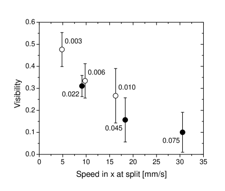
The data suggests that the interferometer coherence decays as the the transverse velocity increases, with calculated as . The decay is due to phase noise. We observe that the rms variation in is about the same throughout, and corresponds to an underlying visibility of about 0.5. This suggests that the loss of visibility comes from to a noise effect related to .
Ideally, the interferometer operation is independent of , since the potential is separable. If the motion in were identical for both packets, then any phase accumulation due to that motion would be identical and thus cancel. However, there are several ways that motion in can couple to the interferometer direction . First, as noted above, driving the -oscillation does produce excitation in of about 0.6 mm/s amplitude. We minimized this effect by selecting the starting time for the experiment such that the motion along was near an extremum. We estimate that the resulting was below 0.1 mm/s, which is too small to explain the observed effects.
More seriously, the standing wave laser is not perfectly aligned to the principle axis of the trap. Observations of trajectories in the trap indicate alignment errors less than a few degrees in the horizontal direction, and a larger error of about in the vertical direction. Atomic motion along and therefore does produce a component along the interferometer direction with magnitude similar to that of the first effect. The beam misalignment is difficult to correct in the current configuration due to limited optical access and the large diameter of the standing-wave beam.
An initial velocity parallel to the standing wave can manifest itself in two ways. First, the beam-splitting and reflection operations are velocity-dependent Hughes et al. (2007). Errors in the operations can leave atoms behind in unwanted momenta, where they can affect the output phase. For instance, if the beam-splitting operation leaves a residual wave packet at , these atoms will continue through the interferometer and act as an additional input state to the final recombination pulse, changing the output in a phase sensitive way. Since the interference signal depends on the square root of the number of atoms in the stray packet, even small errors in the standing-wave operations can result in significant phase shifts. A characteristic of this type of error is a phase-dependent asymmetry between the and populations in the interferometer output, which we do observe at larger .
Even atoms in the correct motional states can acquire phase noise through variations in their trajectory as they traverse the interferometer. This effect can be calculated from the classical action. In a harmonic potential, the action is
| (2) |
where is the velocity, is the position, and . The integral in (2) can be carried out for our trajectory, yielding a phase
| (3) |
where is the unit vector pointing in the direction of the Bragg beam and the vector is defined by for
| (4) |
If , .
For example, using a horizontal alignment error of 1∘, a vertical error of , an amplitude mm with , and ms, we find radians. If fluctuates with a standard deviation , the visibility will be reduced by a factor . We observe fluctuations in the amplitude of about 5%, corresponding to a visibility decrease of 60%, in qualitative agreement with the data above.
On the other hand, values of obtained with ms are generally too small to explain the observed performance. The additional noise may derive from the degraded standing-wave operation described above, since that effect is independent of apart from the velocity’s own dependence on . Modeling suggests that velocity errors on the order of those observed would be sufficient Hughes et al. (2007).
We also estimate the effect of a small anharmonic term in the guide potential, . Again, the resulting phase is calculated using the action, now with the approximate trajectory for an anharmonic oscillator Landau and Lifshitz (1960). To leading order, we find
| (5) |
Numerical modeling of the trap current conductors suggests m-1s-2. With mm, this yields rad. Fluctuations on this value will be too small to contribute significantly to the observed noise, but the effect is not negligible.
In principle, it is possible to model all of these noise effects together and attempt to reproduce the behavior seen in Fig. 2. We pursued such an approach, but found that the results to be very sensitive to the motional noise amplitudes and the alignment angle errors. Our experimental knowledge of these parameters is insufficient to constrain the model enough to be useful, in that the experimental behavior could be reproduced for many different sets of error parameters. The model does, however, further support the conclusion that the mechanisms discussed are sufficient to explain the experimental performance.
Despite the fact that the performance is limited, we believe our approach has promise for creating a compact guided-wave gyroscope. A significant advantage is that the technique is continuously scalable from zero area, a feature that will continue to make troubleshooting easier as the area increases. Additionally, the technique is in principle capable of enclosing larger areas by making repeated loops. If it can be operated with ms, then the split pulse occurs at a turning point in . The trajectory then resembles a vesica piscis as seen in Fig. 1(d). The area in this limit is , and since the trajectory is closed, the atoms can complete multiple orbits. Furthermore, in the configuration the component of the velocity is near zero at the time of the beam-splitting pulses, which would significantly reduce the sensitivity to beam angle described above.
We are currently installing a new magnetic trap apparatus with a more uniform potential along , avoiding the problem of longitudinal decoherence. The new apparatus will also provide optical access allowing the beam alignment errors to be more easily remedied. With these improvements, we expect to increase the useable interferometer duration and reach . We have previously observed interference at one-second measurement times Burke et al. (2008), and if that can be attained here, up to five orbits through the trap would be achievable. This would enclose an effective area of 26 mm2 for mm, comparable to present free-atom gyroscopes, but taking up much less space. It might also be possible to apply the ideas of Search et al. (2009) to this geometry, to increase the sensitivity even further.
Our method is similar to an approach using atoms confined in a cylindrically symmetric harmonic trap Horikoshi and Nakagawa (2007). In that case, reflection operations are not necessary, since the potential itself guides the packets in a circular orbit. After a complete orbit, both the and terms in Eq. (3) vanish, leaving
| (6) |
This too will vanish if is equal to an integer multiple of . We are presently designing a trap to test this symmetric approach as well.
In either geometry, stray interference with erroneous paths may still be problematic, since the beam-splitter operations will never be perfect. The dominant error, from atoms left with after the split, could be resolved by removing those atoms from the trap during the interferometer. In the linear trap, this would require a focused laser beam, but in the cylindrical trap, an rf-evaporation pulse tuned to the bottom of the trap potential would suffice.
We compare these results with other guided-atom gyroscope efforts. Several experiments have demonstrated ring-shaped guides Sauer et al. (2001); Griffin et al. (2008); Gupta et al. (2005); Wu et al. (2004), but none as yet have exhibited interference. Besides the practical problems in creating these potentials such as scalability, there is a more fundamental problem. A ring-guide system will generally exhibit a phase linearly proportional to the initial velocity of the atoms, since tangential motion of atoms around the ring is equivalent to a rotational and thus subject to the Sagnac effect. This effect is much larger than that of Eq. (3): for an equivalent area of mm2, a ring interferometer would exhibit phase noise of 1 rad for a velocity fluctuation of only 1 m/s. In either of the geometries discussed here, this phase largely cancels due to reflection by either the standing wave or the harmonic potential.
The comparable experiment of Wu et al. (2007) avoids this problem, and the use of thermal atoms provides the opportunity to average over unwanted interfering paths. However, the inefficiency of the beam-splitting and reflection operations will make it difficult to achieve trajectories with multiple orbits. Additionally, thermal expansion of the sample disrupts the reciprocality of the trajectories as atoms in the sample move relative to the trap center during the measurement. The use of condensate atoms may thus offer several long-term advantages.
We have demonstrated how a linear interferometer of ultracold atoms in a weak guiding potential can be extended to perform gyroscopic measurements. This gyroscope has an effective enclosed area of 0.05 mm2, but shows promise of being scalable to larger area. Current performance is limited by initial velocity fluctuations, but stabilization of the oscillation-inducing method, improvements in optical access, and optimization of the trap geometry should provide large gains. We hope that in the near future precision rotation measurements with this or a similar device will be possible.
We thank D. Stamper-Kurn for useful conversations, and B. Deissler and K.J. Hughes for their early work on the project. This work was supported by the Defense Advanced Research Projects Agency (Grant No. 51925-PH-DRP) and by the National Science Foundation (Grant No. PHY-0244871).
References
- Berman (1997) P. R. Berman, ed., Atom Interferometry (Academic Press, San Diego, 1997).
- Gustavson et al. (2000) T. L. Gustavson, A. Landragin, and M. A. Kasevich, Class. Quantum Grav. 17, 2385 (2000).
- Durfee et al. (2006) D. Durfee, Y. Shaham, and M. Kasevich, Phys. Rev. Lett. 97, 240801 (2006).
- Sagnac (1913) G. Sagnac, C. R. Acad. Sci. 95, 708 (1913).
- Sauer et al. (2001) J. A. Sauer, M. D. Barrett, and M. S. Chapman, Phys. Rev. Lett. 87, 270401 (2001).
- Wu et al. (2004) S. Wu, W. Rooijakkers, P. Striehl, and M. Prentiss, Phys. Rev. A 70, 013409 (2004).
- Gupta et al. (2005) S. Gupta, K. W. Murch, K. L. Moore, T. P. Purdy, and D. M. Stamper-Kurn, Phys. Rev. Lett. 95, 143201 (2005).
- Wu et al. (2007) S. Wu, E. Su, and M. Prentiss, Phys. Rev. Lett. 99, 173201 (2007).
- Jo et al. (2007) G.-B. Jo, Y. Shin, S. Will, T. Pasquini, M. Saba, W. Ketterle, and D. Pritchard, Phys. Rev. Lett. 98, 030407 (2007).
- Griffin et al. (2008) P. F. Griffin, E. Riis, and A. S. Arnold, Phys. Rev. A 77, 051402(R) (2008).
- Garcia et al. (2006) O. Garcia, B. Deissler, K. J. Hughes, J. M. Reeves, and C. A. Sackett, Phys. Rev. A 74, 031601(R) (2006).
- Burke et al. (2008) J. H. T. Burke, B. Deissler, K. J. Hughes, and C. A. Sackett, Phys. Rev. A. 78, 043404 (2008).
- Tonyushkin and Prentiss (2008) A. Tonyushkin and M. Prentiss, Phys. Rev. A 78, 053625 (2008).
- Reeves et al. (2005) J. M. Reeves, O. Garcia, B. Deissler, K. L. Baranowski, K. J. Hughes, and C. A. Sackett, Phys. Rev. A 72, 051605(R) (2005).
- Wu et al. (2005) S. Wu, Y. Wang, Q. Diot, and M. Prentiss, Phys. Rev. A 71, 043602 (2005).
- Hughes et al. (2007) K. J. Hughes, B. Deissler, J. H. T. Burke, and C. A. Sackett, Phys. Rev. A 76, 035601 (2007).
- Landau and Lifshitz (1960) L. D. Landau and E. M. Lifshitz, Mechanics (Pergamon, New York, 1960), 3rd ed.
- Search et al. (2009) C. Search, J. Toland, and M. Zivkovic, Phys. Rev. A 79, 053607 (2009).
- Horikoshi and Nakagawa (2007) M. Horikoshi and K. Nakagawa, Phys. Rev. Lett. 99, 180401 (2007).