NUMERICAL AND EXPERIMENTAL STUDY FOR A BEAM SYSTEM WITH LOCAL UNILATERAL CONTACT MODELING SATELLITE SOLAR ARRAYS
1 ABSTRACT
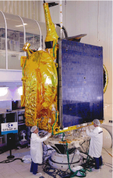
The mass reduction of satellite solar arrays results in significant panel flexibility, so possibly striking one another dynamically leading ultimately to structural damage. To prevent this, rubber snubbers are mounted at well chosen points of the structure and they act as one sided linear spring; as a negative consequence, the dynamic of these panels becomes nonlinear. The finite element approximation is used to solve partial differential equations governing the structural dynamic. The models are validated and adjusted with experiments done in the ISVR laboratory, Southampton university.
2 INTRODUCTION
The study of the total dynamic behavior of solar arrays in a folded position with snubbers are so complicated, that to simplify, a solar array is modeled by a clamped-free Bernoulli beam with one-sided linear spring. This system is subjected to a periodic excitation force.
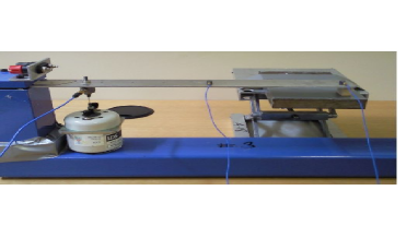
The real state of the problem is close to a beam with unilateral contact subjected to a periodic imposed displacement of the base, but the
dynamical behavior of the system do not change significantly if the imposed displacement is replaced by a periodic force excitation, the configuration used
is easiest to be realized from a technical point of view as the rig is very simple to built [see figure 2]
The present study is to simulate the behavior of a beam which strikes a snubber under a periodic excitation. As the interest is to deal with the first three eigen frequencies, the beam is modeled by ten finite elements.
The results are presented and compared in the frequency domain, the FFT is applied to the predicted and the experimental displacement of the last node of the beam finite element. The mass effect of the force transducer is taken in account in the finite element code. Note that no treatment is done or used from the acquisition system as the problem is nonlinear, the transfer function and the other functions use linear assumptions. The time signal is taken and the processing is done using an external software (Scilab [8]). The numerical predictions compared to experimental results show very good agreement.
3 THE MODEL

The beam motion with a snubber can be modeled as:
| (3.1) |
,
| (3.2) |
The classical Hermite cubic finite element approximation is used, it yields an ordinary differential system in the form:
| (3.3) |
Where and are respectively the mass and stiffness assembled matrices, q is the vector of degrees of freedom of the beam,
, , where is the size of , and are the indices of the nodes where the spring and the excitation force meet the beam respectively. Numerical time integration was performed using ODE numerical integration for ’stiff’ problems, package ODEPACK is called and it uses the BDF method.
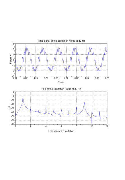
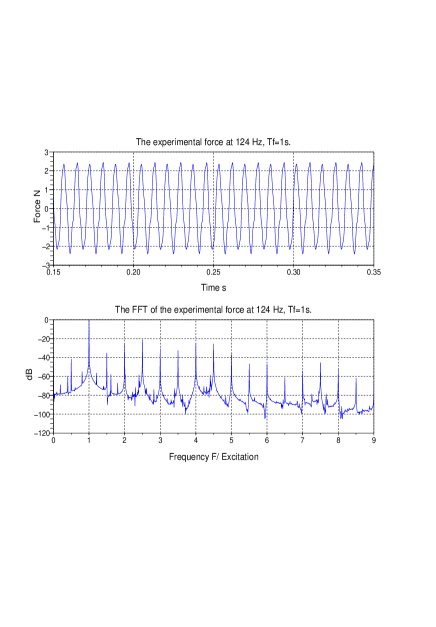
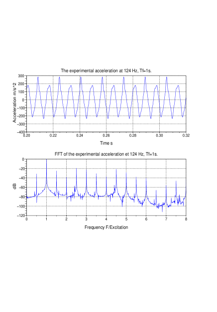
The use of a small electrodynamic shaker yields a technical problem due to the reaction of the beam, the input force can not be a simple sine wave. To deal with this problem, a force transducer is fixed between the shaker and the beam. The numerical codes use the actual force time signal coming from the acquisition system which is periodic. Figure shows the input force signals with its spectrum contents.
4 EXPERIMENTAL AND NUMERICAL RESULTS
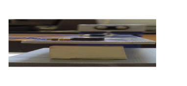
Figures [2] and [3] give a clear idea of the experiment setup. In the table, all the parameters used in the simulations and the experiments are shown as well as the first three predicted eigen frequencies of the linear beam without the spring. The integration time is fixed at for all the simulations and the experiment sequences which is five times the greater period of the system.
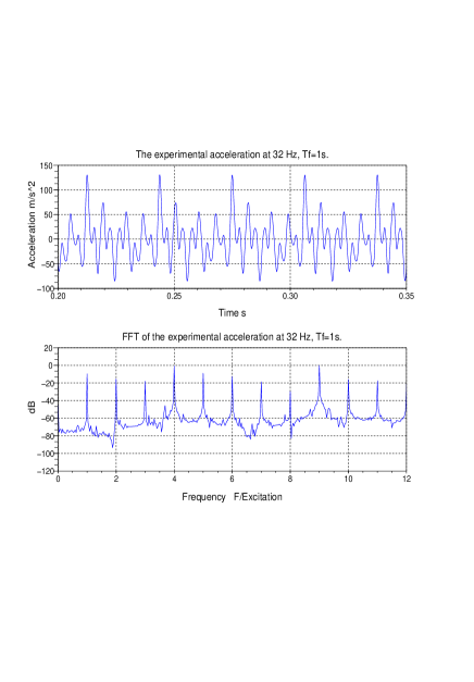
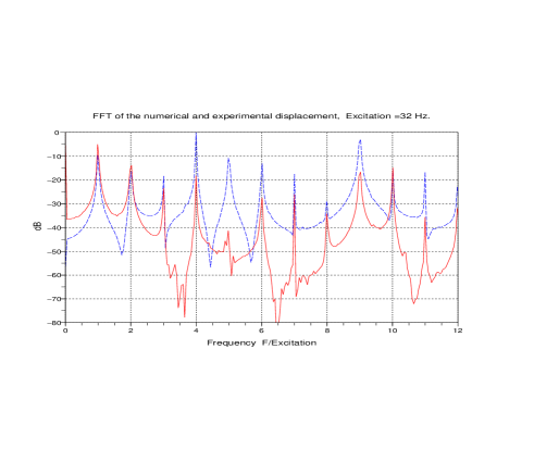
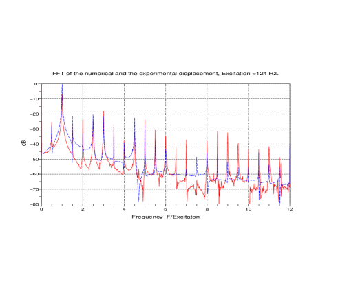
Figure shows the FFT of the numerical and the experimental displacements for and , the height of the peaks are normalized by the maximum; the predicted frequencies found are exactly the same measured for a large number of harmonics. However, a small shift in the height of these pikes appears from the fifth harmonic, this is maybe due to the low number of finite elements used to model the beam; some investigations are in progress to understand this aspect. Other tests with random excitations have shown good agreement. The effect of the unilateral contact is underlined, the input frequency is split into its all harmonics.
Figures and show the input excitation force, it is clear from the time signal and from its frequency content that this force is not a single sine wave, but it is periodic.
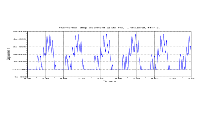
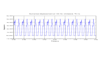
Figure shows the predicted displacement for an excitation of and , the displacement is almost positive, this is due to the high stiffness of the spring but the time response is still periodic.
Note that the frequencies and are chosen and presented herein because they represent the first two nonlinear normal modes of the nonlinear normal mode, they are computed numerically by a numerical sweep test. Non linear normal modes of a nonlinear differential systems are an extension of the well known linear normal modes,another interest of the authors with some papers in progress.
|
(4.1) |
References
- [1] J. H. Bonsel, R. H. B. Fey. and H. Nijmeirjer: Application of a Dynamic Vibration Absorber to a Piecewise Linear Beam System. Nonlinear Dynamics 37: 227-243, 2004.
- [3] D.Jiang,C.Pierre, S.W. Shaw: Large-amplitude non-linéar normal modes of piecewise linear systems. Journal of sound and vibration 272 (2004) 869-891
-
[3]
Rob H.B. Fey and Berend Winter, Jaap J. Wijker
Sine sweep and steady - state response of a simplified solar array model with nonlinear support. DETC99/VIB-8027, 1999 ASME Design Engineering Technical Conferences, Las Vegas, Nevada, USA. -
[4]
R.H.B. Fey and F.P.H. van Liempt :
Sine sweep and steady-state response of a simplified solar array model with nonlinear elements. International conference on Structural Dynamics Modelling, 3-5 june 2002, pp.201-210. - [5] M Géradin Théorie des vibrations: applications à la dynamique des structures. Masson Paris 2eme edition 1996
- [6] Stéphane Junca et Bernard Rousselet: Asymptotic Expansions of Vibrations with Unilateral Contact, proceeding of the GDR 2501-Anglet 2-6 Juin 2008.
- [7] Richard H. Rand:Lecture Notes on Nonlinear Vibrations, Dept. Theoretical Applied Mechanics Cornell University Ithaca NY 14853
- [8] Scilab [www.scilab.org]
- [9] E.L.B. Van De Vorst, M.F.Heertjes D.H. Van Campen and A. De Kraker and R.H. B. Fey: Experimental and numerical analysis of the steady state begavior of a beam system with impact. Journal of Sound and Vibration 1998 212(2), 210-225