Submarine neutrino communication
Abstract
We discuss the possibility to use a high energy neutrino beam from a muon storage ring to provide one way communication with a submerged submarine. Neutrino interactions produce muons which can be detected either, directly when they pass through the submarine or by their emission of Cerenkov light in sea water, which, in turn, can be exploited with sensitive photo detectors. Due to the very high neutrino flux from a muon storage ring, it is sufficient to mount either detection system directly onto the hull of the submersible. The achievable data transfer rates compare favorable with existing technologies and do allow for a communication at the usual speed and depth of submarines.
The use of neutrino beams for communication is an old idea and has been put forth by several authors for various purposes, like for e.g interstellar or even intergalactic communication Pasachoff and Kutner (1979); Subotowicz (1979); Learned et al. (2009); Silagadze (2008). Also the the use of neutrinos for communication with a submarine deep under the ocean has been previously considered Saenz et al. (1977); Callan et al. (1988), however the conclusion was that this does not provide a feasible approach222The use of hypothetical particles for this purpose is discussed in reference Jaeckel et al. (2009).. In this letter, we carefully reexamine the problem and will find that recent technological advances require to reconsider the earlier negative conclusion.
Nuclear powered submarines offer, practically, unlimited submerged endurance; they are only tied to the surface by their need to communicate. Therefore, communication at operational speed and depth is highly desirable. Currently, only radio transmission at extremely low frequency (elf) of is able provide communication at speed and depth. elf data rates are very low, of order one bit per minute because of the very low bandwidth, the high noise levels and the difficulty to generate high-powered signals Burrows and Niessen (1972). Instead radio transmission at frequencies of a few kHz (very low frequency, vlf) are used, providing data rates around Carter (1987); however, the sea water penetration of vlf is limited. This requires a wire antenna, floated close to the surface, which entails significant operational limitations.
The basic concept for submarine neutrino communication (snc), derives from the fact that neutrinos can traverse an entire planet. Neutrinos can be sent from one point on the surface of the earth to a submarine, irrespective of its location and depth. The feebleness of neutrino interactions implies a large detector and a very bright neutrino source. One of the currently most intense neutrino beams is used in the minos experiment Adamson et al. (2008), where a beam of neutrinos is sent from the Fermi National Accelerator Laboratory in Chicago to a mine in northern Minnesota over a distance of more than . During the 2 years duration of the experiment, the neutrino beam produced 730 muons in of detector. This is equivalent to one neutrino event every 12 hours. Obviously, an improvement of at least 6 orders of magnitude is required.
Muon storage rings have been proposed as source of highly collimated neutrino beams Geer (1998) in order to allow precision measurements of the neutrino mixing parameters Bandyopadhyay et al. (2007). In these facilities muons will be produced from pion decay and the pions are produced by proton irradiation of a target. Current designs for such a facility assume useful muon and useful anti-muon decays with muon energies in the range from . Such a facility also would constitute the first step towards a multi-TeV muon collider. The short lifetime of the muon and the high proton beam power are the main technical challenges. Currently, several R&D experiments are underway, for a recent review see Berg et al. (2008), in order to prove the feasibility of this concept.
The muon neutrino flux from a storage ring with unpolarized muons of energy is given by
| (1) |
where is the number of muon decays, , denotes the muon mass and is the Cartesian distance from the storage ring. The beam divergence, . These neutrinos will interact in sea water and produce muons in this process, with a cross section of , with , and . The cross section for anti-neutrinos is obtained by interchanging and . The range of a muon, , with energy in water can be parametrized Grieder (2001) as in the range . The resulting muon flux per unit area is obtained from
| (2) |
where is the density of sea water, is Avogadro’s number and is the smallest acceptable muon energy. The anti-muon flux is obtained by replacing the cross section and flux with the corresponding quantities for anti-neutrinos. The requirement that the muon direction is within less than a maximum angle of the original neutrino direction, translates, by simple kinematics, into a lower bound on the muon energy , . Also, we may set a minimum muon energy every muon should have, in which case . From equation 2 we obtain including both neutrinos and anti-neutrinos, with , , , , and , which is the area in which a muon can be detected, a muon rate of ; note, that . A neutrino source delivering muons at a rate of with an energy of would require about in proton beam power and acceleration power, which for a electrical efficiency translates into a total power consumption of roughly . In order to aim the beam, it is necessary to point the long straight section of the muon storage ring towards the submarine. The storage ring is relatively large, but also quite lightweight and thus one solution could be to suspend the storage ring in water, either in a lake or close to shore, and use buoyant forces to aim it. Also, stronger magnets combined with shorter straight sections, can reduce the size of the ring substantially. The aiming of the beam represents a considerable engineering challenge but hardly can be considered an insurmountable obstacle.
How many bits of information can be transmitted by one neutrino? snc, in this respect, is very similar to deep space optical communications, where very few photons need to carry the largest possible amount of information Hemmati (2006). This is achieved by using pulse position modulation (ppm), where one unit of time is divided into slots and we can freely chose in which of these slots we transmit the pulse. Of course, if enough photons/neutrinos are available we can decide to transmit a number, , of pulses per unit time. In the context of a muon storage ring, the number of slots is determined by the inverse of the duty factor. Duty factors of the order of seem feasible, therefore we will take . The optimum number of pulses will depend on the available muon event rate. In the context of information theory the above system corresponds, in the absence of backgrounds, to an -ary Poisson erasure channel. The capacity of an information channel is the theoretically maximal rate at which information can be transmitted with an arbitrarily small error probability. In practice, a coding scheme is required to achieve good performance. However, research in the last decade or so has produced a number of practical coding schemes which actually can perform very close to capacity, see e.g. McKay (2003). The capacity, in our case, given as a function of Georghiades (1994) is
| (5) | |||
| (10) |
where is the erasure probability, which for a Poisson process is with being the number of events per unit time. For a given value of and we can determine the optimum number of pulses which maximizes the capacity. For the maximum capacity, , can be parametrized as . Using the previous result on we obtain a capacity of even at the antipodes of the sender.
Muons from cosmic ray interactions in the atmosphere and muons produced by neutrinos from the same cosmic ray interactions are a source of irreducible background. The muon flux at a water depth of is Grieder (2001), which for yields a background of . This flux, however, is entirely down going, i.e. there are no atmospheric muons from below the horizon. Thus, this background is problematic only as far as muons coming from the upper hemisphere are erroneously reconstructed as coming from below. Neutrino telescopes, like antares or IceCube have demonstrated that the fraction of muons mis-reconstructed in this way is of the order Achterberg et al. (2007). Moreover, for neutrinos stemming from a beam, we require the resulting muons to lie within a cone with an opening angle of around the beam direction which yields another factor of 10 reduction. Thus, the resulting effective background rate, even close to the water surface is at most . The event rate from atmospheric neutrinos with energies above is a few events per day. Therefore, these backgrounds are at least 1000 times smaller than the signal and thus, can be safely neglected.
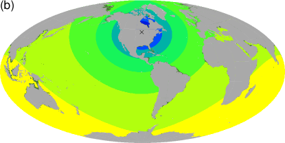
The most straightforward approach to muon detection is to convert the submarine itself into a muon detector: a modern submarine is approximately a cylinder of diameter and length, which allows an effective muon detection area of . We would use thin muon detector modules which can be used very much like wallpaper to cover the majority of the vessel’s hull333Note, that submarines have actually two hulls, a so called light hull, which defines the exterior, hydrodynamic shape and a pressure hull, which protects the crew and equipment from the hydrostatic pressure. All detectors we consider, would be either mounted onto the light hull or in the space between the light and pressure hull.. The muons would enter on one side of the submarine and leave it on the other side. The entry and exit points are measured and thus the the muon direction can be reconstructed quite precisely. Thin, flat and possibly flexible, large area muon detectors exist in various forms like plastic scintillators, gas electron multipliers, see e.g. Aune et al. (2009), resistive plate chambers, etc. The requirements in terms of timing and spatial resolution would be well within the bounds of existing technologies and large area muon detectors are part of many high energy physics experiments. By exploiting local coincidence and coincidence across the vessel non-muon backgrounds like local radioactivity, either in the water or on-board the submarine, can be effectively rejected. Random coincidences from two or more muons striking opposite walls of the submarine can be effectively controlled by requiring the timing of the events to match the timing of an actual, single beam muon444The rate of muon bundles, i.e. several muons originating from the same cosmic ray primary, is small enough not to affect our background estimates, see e.g. Abdallah et al. (2007).. This approach of muon detection which we will refer to as direct, has the advantage that the achievable and hence data transmission rate does not depend on environmental factors. The global distribution of data transmission rates for the direct detection scheme is shown in figure 1b, taking .
Muon detection in a transparent medium, like sea water, can be efficiently achieved by exploiting Cerenkov light, which is emitted along a cone with a constant opening angle, ; in water . The number of photons emitted per unit length of the muon track in the wavelength range , corresponding to the region of maximum transmission in sea water, is . The number of photons at the detector, , which is a distance, , away from the track is , where is the absorption length, is the detector area and is the quantum efficiency of the detector. Setting a trigger threshold of , we can solve for the distance up to which a muon will yield at least photons. The effective muon detection area is then . In order to allow track reconstruction, especially in the presence of backgrounds, it will be necessary to deploy a number, , of photon detectors, each with area . In this case, the total number of signal photons, will be and the total effective photon detection area, will be .
Before we delve in detail into photonic backgrounds, it is useful to summarize the properties of the signal:
-
1.
Cerenkov light is emitted on a cone surrounding the muon track and in absence of scattering will travel in a straight line. Therefore, the relation between the arrival time of a photon at the photo-detector and its point of origin is unique.
-
2.
The arrival directions at each detector must satisfy the Cerenkov condition, i.e. the angle between the direction of muon and the photon must be the Cerenkov angle . Furthermore, the arrival direction, when traced back must intersect the muon track at one point.
-
3.
The mean number of photons at each detector is determined by the distance between the detector and the track.
We will give a combinatorial argument for the approximate background rejection which can be obtained by exploiting these signatures. Assuming a timing resolution of each detector of we want each detector to be no larger than . Conversely, each detector sees the track for no longer than and thus we have a background suppression of . Obviously, the detector area, , can be no larger than . To keep the total number of photons detected constant it will be necessary to increase the number of detectors, , such that stays constant. Also, individual detectors should be spaced no closer than . At the same time, sets the scale down to which the components of a track vector be determined. If we assume a linear array of photo-detectors with a length , then the angular resolution of the array is approximately given by . Since we know that the muon must lie within of the beam direction, there can be, , different angles for a valid signal muon track . The photon detectors survey an area with a maximal resolution of , thus there can be different origins for the muon track . And finally, there can be different event starting times, . Altogether, there can be different valid muon tracks. For and , we obtain .
Along each, of these distinct, possible tracks there can be random fluctuation of stochastic backgrounds from either actual photons, radioactive decays or electronic noise. Irrespective of their origin they all share the property of being random and thus are neither correlated in space nor time. The total background is given by , where is the background rate in units of . The track is seen at each individual photo-detector for only , thus we need to be concerned only about background in the window , i.e. we obtain an immediate background suppression of and the effective background, . We next require that the probability of the effective background to fluctuate up to the signal is smaller than , thus ensuring that on average there are nor more than random coincidence events per second happen in the entire detector and we use . For large and , the probability can be approximated by a Gaußian and we can solve for as a function of and obtain with and where denotes the inverse of the complementary error function.
So far, we have not made use of the photon arrival direction as discussed in point 2. Reconstruction of the photon arrival directions with a resolution of will result in a background suppression, , of . A simple optical system like a lens or mirror can translate the arrival direction of a photon into the position in the focal plane. Finally, the photon background can be as large as
| (11) |
without causing a fake muon rate in excess of . For a given , we can set the trigger threshold such that is sufficiently large for equation 11 to hold. , in turn, determines, together with , how far out or at which maximal distance, , a muon can be seen above background and thus sets the size of .
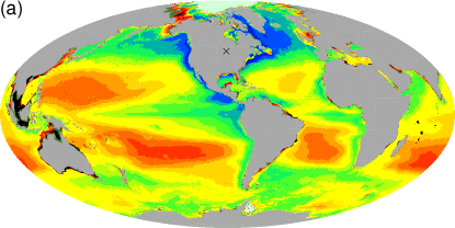
Next, we need to compare this rate to the various background light sources. The light produced by natural radioactivity, mainly from 40K, and the light from bio-luminescence is, at the depths we consider, negligible compared to the photons from the surface Escoffier (2007). Nonetheless, we include a random noise rate due to 40K and bio-luminescence of , this corresponds to 20 times the maximum noise reported in Escoffier (2007). At a water depth, , the photon flux, will be where is the attenuation length and the photon flux at the surface. The photon flux from the sun in the zenith, in the wavelength range , is . At night the surface photon flux will be at least times smaller. The larger the optical overburden the smaller can be chosen and the larger the resulting will be and vice versa.
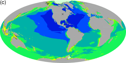
The optical properties of sea water play a crucial role for both the available target mass, and thus signal level as well as for the photon background. The attenuation length of sea water at a wavelength of can be determined in situ by spectroscopy of the upwelling sun light. There are currently two satellites, Aqua and Terra, which carry on board the Moderate Resolution Imaging Spectroradiometers (modis) and provide nearly global coverage. This method has been validated by surface measurements, but, essentially, is sensitive only to a depth down to one attenuation length. Therefore, we will make the assumption that the attenuation length close to the surface is representative of the one at greater depth. We use a data set which has been averaged over 7 years and which has a spatial resolution of Feldman and McClain (2009). In order to estimate the available overburden we use global bathymetry data Amante and Eakins (2008) with a horizontal resolution of . For our numerical results we assume a diving depth of and a photon detection area with , and . We predict the expected information capacity: the results are shown for day time in figure 1a and for night time in figure 1c.
How such a system would be used operationally is difficult to assess, since our knowledge of submarine operations is insufficient to provide a in depth discussion. Obviously, the position of a submarine is secret and ideally not known to anyone outside the vessel. However, in order to send messages using a neutrino beam we need know the position of the submarine within the width of the beam of . One solution, is to point the beam at prearranged times to prearranged locations within the patrol area of the submarine and the submarine will be at one of these points at the right time at least a certain number of times per day. Another possibility, is to artificially increase the beam spot size by sweeping the beam across the suspected course of the submarine. The resulting data rate is low, but all that needs to transmitted is the request to sail to a prearranged location for the reception of high speed communication. Assuming a reduced data rate corresponding to the elf data rate of 1 bit per minute, it follows from the expression for that a muon rate of is sufficient. This rate is more than 7000 times smaller than the rate for a fully focused beam. The fully focused beam has an opening angle of , corresponding to a beam spot area of about at distance of . Since we need only of the focused beam flux, we can sweep the beam over an area times larger than the beam spot area, which is , corresponding to a sweep radius of . Note, that the sweep radius scales like and we have assumed direct detection only, optical detection would yield significantly larger sweep radii. Finally, one could establish a neutrino mailbox, consisting of a string moored to the seafloor, which has photo detectors attached, very similar to a single string of a conventional neutrino telescope like antares. The mailbox can be filled at very high data rate due to the deep sea location and resulting very low noise. The message is stored locally and can be retrieved by the submarine using short range communications. Each mailbox would be relatively cheap and thus a sizable number can be distributed throughout the patrol area. If one requires that the submarine is never further than 1 hour away from a mailbox and that the speed of a submarine is 20 knots, one obtains that each mailbox serves an area of . At 8 hour travel time an area similar to the one obtained from sweeping the beam can be covered by a single string and about 1400 strings would cover all oceans. Note, that the message size, due to the long integration time of several hours combined with the high data rate, can reach many 100 kilobyte.
| day | direct | night | |
|---|---|---|---|
| 1 | 90 | 100 | 100 |
| 10 | 41 | 73 | 100 |
| 100 | 4 | 2 | 28 |
Table 1 summarizes our results succinctly. We have demonstrated that a neutrino beam from a muon storage ring can be detected by sensors mounted on the hull of a submarine. This in principle would allow to establish a one-way communication link at speed and depth with data rates in the range from which improves current elf data rates by 1-3 orders of magnitude and is similar to data rates offered by vlf.
Acknowledgements.
I am especially thankful to S. Kubrick and P. Sellers whose work served as inspiration. I also, would like to acknowledge useful conversations with J.M. Link and D. Mohapatra.References
- Learned et al. (2009) J. G. Learned, S. Pakvasa, and A. Zee, Phys. Lett. B671, 15 (2009), eprint 0805.2429.
- Silagadze (2008) Z. K. Silagadze, Acta Phys. Polon. B39, 2943 (2008), eprint 0803.0409.
- Pasachoff and Kutner (1979) J. M. Pasachoff and M. L. Kutner, Cosmic Search 1 (1979).
- Subotowicz (1979) M. Subotowicz, Acta Astronomica 6, 213 (1979).
- Saenz et al. (1977) A. W. Saenz, H. Uberall, F. J. Kelly, D. W. Padgett, and N. Seeman, Science 198, 295 (1977).
- Callan et al. (1988) C. Callan, F. Dyson, and S. Treiman (1988), JASON, The MITRE Corporation.
- Jaeckel et al. (2009) J. Jaeckel, J. Redondo, and A. Ringwald, Europhys. Lett. 87, 10010 (2009), eprint 0903.5300.
- Burrows and Niessen (1972) M. L. Burrows and W. C. Niessen, Oceans pp. 95–109 (1972).
- Carter (1987) A. B. Carter, in Managing nuclear options (The Brookings Institution, 1987).
- Adamson et al. (2008) P. Adamson et al. (MINOS), Phys. Rev. Lett. 101, 131802 (2008), eprint 0806.2237.
- Geer (1998) S. Geer, Phys. Rev. D57, 6989 (1998), eprint hep-ph/9712290.
- Bandyopadhyay et al. (2007) A. Bandyopadhyay et al. (ISS Physics Working Group) (2007), eprint 0710.4947.
- Berg et al. (2008) J. S. Berg et al. (ISS Accelerator Working Group) (2008), eprint 0802.4023.
- Grieder (2001) P. K. F. Grieder, Cosmic rays at earth (Elsevier, 2001).
- Hemmati (2006) H. Hemmati, ed., Deep space optical communication (Wiley-Interscience, 2006).
- McKay (2003) D. J. McKay, Information Theory, Inference, and Learning Algorithms (Cambridge University Press, 2003).
- Georghiades (1994) C. N. Georghiades, IEEE Transactions on Information Theory 40, 1313 (1994).
- Achterberg et al. (2007) A. Achterberg et al. (The IceCube), Phys. Rev. D76, 027101 (2007), eprint 0705.1781.
- Aune et al. (2009) S. Aune et al., Nucl. Instrum. Meth. A604, 53 (2009).
- Abdallah et al. (2007) J. Abdallah et al. (DELPHI), Astropart. Phys. 28, 273 (2007), eprint 0706.2561.
- Escoffier (2007) . S. Escoffier (ANTARES) (2007), eprint 0710.0527.
- Feldman and McClain (2009) G. C. Feldman and C. R. McClain, Ocean color web, http://oceancolor.gsfc.nasa.gov/ (2009), NASA Goddard Space Flight Center. Eds. Kuring, N., Bailey, S. W.
- Amante and Eakins (2008) C. Amante and B. W. Eakins (2008), national Geophysical Data Center, NESDIS, NOAA, U.S. Department of Commerce.