Giant Slow Wave Resonance for Light Amplification and Lasing
Abstract
We apply the idea of giant slow wave resonance associated with a degenerate photonic band edge to gain enhancement of active media. This approach allows to dramatically reduce the size of slow wave resonator while improving its performance as gain enhancer for light amplification and lasing. It also allows to reduce the lasing threshold of the slow wave optical resonator by at least an order of magnitude.
1 Introduction
Light-matter interactions play essential role in optics. Well-known effects caused by light-matter interactions include: nonreciprocal circular birefringence responsible for magnetic Faraday rotation, all kinds of nonlinear effects, gain in active media, etc. At optical frequencies, the above interactions are usually weak and can be further obscured by absorption, radiation losses, etc. A way to enhance those interactions is to place the optical material in a resonator. In cases of gain in active media or Faraday rotation, a simple intuitive explanation for the resonance enlacement of the respective effect invokes the idea that in a high-Q resonator filled with the proper optical material, each individual photon resides much longer compared to the same piece of material taken out of the resonator. Since all the mentioned above interactions are independent of the direction of light propagation, one can assume that their magnitude is proportional to the photon residence time in the optical material. With certain reservations, the above assumption does provide a hand-waving explanation of the phenomenon of resonance enhancement. The above qualitative picture may not directly apply to composite structures in which the size of individual uniform components is comparable to or lesser than the electromagnetic wavelength. At the same time, a number of popular methods of resonance enhancement of light-matter interactions involve some kind of composite dielectric structure, in which the typical feature size is comparable to the electromagnetic wavelength.
The majority of high-Q optical resonators fall into one of the following two categories: (a) cavity resonators, exemplified by optical microcavities in which light confinement is produced by Bragg reflectors or by total internal reflection (e.g., the whispering galery modes) and (b) slow wave resonators, exemplified by periodic stacks of dielectric layers and photonic crystals with two- and three-dimensional periodicity. Either kind of optical resonator has certain advantages and disadvantages. Detailed information on resonant microcavities can be found in numerous papers and monographs on photonics (see, for example, [20] and references therein). Further in this paper we will not discuss cavity resonators, focusing instead on slow wave resonators and their applications in gain enhancement. Gain enhancement is essential in light amplification and lasing. It can also be used to offset losses produced by other material components of the composite structure.
There can be two independent mechanisms of gain enhancement in a slow wave photonic structure. The first one is associated with slow wave resonance, which is often referred to as a Fabry-Perot resonance, or a transmission band edge resonance. This mechanism works the best in high-Q slow wave resonators where the amplitude of the oscillating electromagnetic field is much higher than that of the incident light (for more information see, for example, [21, 7, 8, 9, 22, 23, 24, 25, 26], and references therein). Another mechanism of gain enhancement in a photonic structure is associated with the microscopic field distribution inside the periodic dielectric array. Specifically, the oscillating electric component of light should be concentrated in the gain component of the composite structure, rather than in the other material component. This latter idea is very similar to that used in [1] for absorption suppression in magnetic photonic crystals.
The central idea of this paper is to use the so-called giant slow wave resonance [2, 3] for gain enhancement. This approach allows to reduce the size of slow wave resonator while dramatically improving its performance as gain enhancer. It could be particularly attractive for light amplification and lasing. In the latter case, not only it allows to reduce the size of the optical resonator, but it can also significantly lower the lasing threshold.
1.1 Giant slow wave resonance
Electromagnetic wave propagation in photonic crystals is qualitatively different from any uniform substance. The differences are particularly pronounced when the wavelength is comparable to the size of the unit [4, 5, 6, 7, 8, 9, 10]. The effects of strong spatial dispersion culminate at stationary points of the Bloch dispersion relation where the group velocity of at least one of the traveling Bloch wave vanishes
| (1) |
There are several reason for that. Firstly, vanishing group velocity always implies a dramatic increase in density of modes at the respective frequency. Secondly, vanishing group velocity implies certain qualitative changes in the eigenmode structure, which can be accompanied by some spectacular effects in light propagation. One such example is the frozen mode regime associated with a dramatic amplitude enhancement of the wave transmitted to the periodic medium [11, 12, 13, 14, 15, 16]. In this paper, we focus on a different slow-wave effect, namely, on slow wave resonance occurring in bounded photonic crystals at frequencies close to photonic band edges. This slow wave phenomenon is also referred to as the transmission band edge resonance. There are some similarities between the frozen mode regime and the slow-wave resonance in plane-parallel photonic crystals. Both effects are associated with vanishing group velocity at stationary point (1) of the Bloch dispersion relation. As a consequence, both effects are strongly dependent on specific type of spectral singularity (1). A fundamental difference though is that the frozen mode regime is not a resonance phenomenon in a sense that it is not particularly sensitive to the shape and size of the photonic crystal. For instance, the frozen mode regime can occur even in a semi-infinite periodic structure, where the incident plane wave is converted to a frozen mode slowly propagating through the periodic medium until it is absorbed [11, 12, 13, 14, 15, 16]. By contrast, in the case of a slow wave resonance, the entire bounded periodic structure acts as a resonator, resulting in strong sensitivity of the resonance behavior to the size and shape of the photonic crystal.
The idea of giant slow-wave resonator was proposed in [2, 3]. The giant transmission band-edge resonance is produced by slow waves associated with a degenerate band edge (DBE). The DBE related slow wave resonance is much more powerful compared to those achievable in common layered and other periodic arrays displaying only regular photonic band edges (RBE). Specifically, at the frequency of DBE related giant slow-wave resonance, the electromagnetic energy density inside the photonic-crystal can be estimated as
| (2) |
where is the energy density of the incident wave and is the total number of unit cells in the periodic stack. The respective Q-factor is
By comparison, the average EM energy density at a standard RBE related resonance is
| (3) |
The respective Q-factor is
And this a huge difference! Our goal is to find out how to use this advantage of the DBE-ralated giant slow wave resonance for light amplification and lasing.
2 Light propagation in periodic arrays of birefringent layers
In this section we introduce some basic definitions and notations of electrodynamics of stratified media composed of birefringent layers. Similar results can be obtained in photonic crystals with two- or three-dimensional periodicity, where the presence of birefringent optical materials is not required. Also, one could consider corrugated optical waveguides.
2.1 Transverse time-harmonic waves in stratified media
In a stratified medium, the second rank tensors and depend on a single Cartesian coordinate , normal to the layers. The Maxwell equations in this case can be recast as
| (4) |
Solutions for Eq. (4) are sought in the following form
| (5) |
The substitution (5) allows separation of the tangential components of the fields into a closed system of four linear ordinary differential equations
| (6) |
where
| (7) |
and the matrix is referred to as the (reduced) Maxwell operator. The normal field components and do not enter the reduced Maxwell equations (6) and can be expressed in terms of the tangential field components from Eq. (6) as
| (8) |
where
Waves propagating in the direction in transverse medium are referred to as transverse waves
| (9) |
The respective Maxwell operator has the following simple form
| (10) |
where we put .
The values of at any two different locations and are related by the transfer matrix defined by
| (11) |
The elements of the transfer matrix are expressed in terms of material tensors and other physical characteristics of the stratified medium.
Let , , and be the incident, reflected, and transmitted waves, respectively. To the left of the stack (at ), the electromagnetic field is a superposition of the incident and reflected waves. To the right of the stack (at ), there is only the transmitted wave. The field inside the periodic medium is denoted as . Since all four transverse field components in (7) are continuous functions of , we have the following boundary conditions at and
| (12) |
| (13) |
At any given frequency , the time-harmonic field inside the periodic stratified medium can be represented as a superposition of Bloch eigenmodes, each of which satisfies the following relation
| (14) |
or, equivalently,
| (15) |
The Bloch wave number is defined up to a multiple of . The correspondence between and is referred to as the Bloch dispersion relation. Real correspond to propagating (traveling) Bloch modes. Propagating modes belong to different spectral branches separated by frequency gaps. In reciprocal and/or centrosymmetric periodic structures, the Bloch dispersion relation is always symmetric with respect to the points and of the Brillouin zone
| (16) |
where
| (17) |
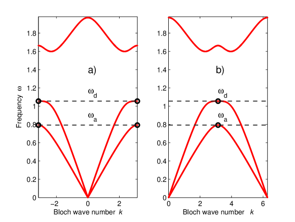
In periodic structures composed of non-birefringent layers, every Bloch wave is doubly degenerate with respect to polarization. If, on the other hand, some of the layers display an in-plane anisotropy or gyrotropy, the polarization degeneracy can be lifted. The respective diagrams are shown in Fig. 1.
The speed of a traveling wave in a periodic medium is determined by the group velocity . Normally, every spectral branch develops stationary points (1) where the group velocity of the corresponding propagating mode vanishes. Usually, such points are located at the center and at the boundary of the Brillouin zone
| (18) |
This is always the case in periodic layered structures composed of non-birefringent layers, where all stationary points coincide with photonic band edges. If, on the other hand, some of the layers in a unit cell are birefringent, then in addition to (18), some dispersion curves can also develop a reciprocal pair of stationary points corresponding to a general value of the Bloch wave number , as shown in Fig. 1. The respective portion of the diagram can be described as a split band edge (SBE). The dispersion relation can develop a DBE or a SBE only if the periodic layered array has birefringent layers with misaligned in-plane anisotropy [2, 16]. Examples of such layered structures can be found in [2, 16, 3].
Unlike propagating modes, evanescent Bloch modes are characterized by complex wave numbers . Under normal circumstances, evanescent modes decay exponentially with the distance from the periodic structure boundaries. In such cases, the evanescent contribution to can be significant only in close proximity of the surface or some other defects of the periodic structure. The situation can change dramatically in the vicinity of a stationary point (1) of the dispersion relation. At first sight, stationary points (1) relate only to propagating Bloch modes. But in fact, in the vicinity of every stationary point frequency , the imaginary part of the Bloch wave number of at least one of the evanescent modes also vanishes. As a consequence, the respective evanescent mode decays very slowly, and its role may extend far beyond the photonic crystal boundary. In addition, in some special cases, the electromagnetic field distribution in the coexisting propagating and/or evanescent eigenmodes becomes very similar, as approaches . This can result in a spectacular effect of coherent interference, such as the frozen mode regime [11, 12, 15, 16]. What exactly happens in the vicinity of a particular stationary point essentially depends on its character and appears to be very different for different types of singularity (1).
Using the transfer matrix (11), the Bloch relation (14) can be recast as
| (19) |
where is the transfer matrix of a unit cell
At any given frequency, there are four Bloch eigenmodes, propagating and/or evanescent, with different polarizations and wave numbers
| (20) |
In the presence of absorption and/or gain, all four Bloch wave numbers can be complex at any finite frequency.
2.2 EM energy flux in layered media
The real-valued energy flux (the Poynting vector) associated with time-harmonic field (7) is
| (21) |
Let , , and be the energy fluxes of the incident, reflected, and transmitted waves, respectively. The transmission/reflection coefficients and are defined as
| (22) |
In case of lossy medium, we should also introduce the absorption coefficient
| (23) |
In case of active media, instead of absorption we should introduce the gain coefficient
| (24) |
In isotropic material with absorption and/or gain, the dielectric permittivity is
Assuming that , in a lossy medium, the ratio is positive
| (25) |
while in a gain medium, the same ratio is negative
| (26) |
3 Conclusion.
In summary, let us reiterate the following basic questions. What happens to the giant slow wave resonance in the presence of moderate losses or moderate gain? How does the total gain defined in (24) behave in the vicinity of the resonance frequency. How do the above characteristics of the giant slow wave resonance compare to those of the standard slow wave resonance in the vicinity of a regular photonic band edge (RBE)?
Our analysis shows for small values of the ratio from (26), the total gain coefficient is proportional to , both in the case of giant slow wave resonance at DBE, and in the case of regular slow wave resonance at RBE. The difference, though, is that in the former case
while in the latter case
where is the incident light intensity and is the number of layers in the periodic stack. It means, for instance, that for , the giant slow wave resonance produces roughly times stronger gain, compared to that of the regular slow wave resonance in the same stack. To put it differently, to produce the same gain , the stack with a DBE needs by fewer layers, compared to the regular slow wave resonator. As the ratio further increases, it reaches the threshold value, which is the case of DBE-related slow wave resonator is lower by the factor . The above figures are rather impressive. They show that the giant slow wave resonance is overwhelmingly better than the regular slow wave resonance, when it comes to light amplification and lasing.
Acknowledgment and Disclaimer: Effort of A. Figotin and I. Vitebskiy is sponsored by the Air Force Office of Scientific Research, Air Force Materials Command, USAF, under grant number FA9550-04-1-0359. The authors are thankful to A. Chabanov for stimulating discussions.
References
- [1] A. Figotin and I. Vitebskiy. Absorption suppression in photonic crystals. Physical Review B77, 104421 (2008)
- [2] A. Figotin and I. Vitebskiy. Gigantic transmission band-edge resonance. Phys. Rev. E72, 036619 (2005).
- [3] A. Figotin and I. Vitebskiy. Slow-wave resonance in periodic stacks of anisotropic layers. Phys. Rev. A76, 053839 (2007)
- [4] L. Brillouin. Wave Propagation and Group Velocity. (Academic, New York, 1960).
- [5] L. D. Landau, E. M. Lifshitz, L. P. Pitaevskii. Electrodynamics of continuous media. (Pergamon, N.Y. 1984).
- [6] J. Joannopoulos, R. Meade, and J. Winn. Photonic Crystals. (Princeton University Press, 1995).
- [7] A. Yariv and Pochi Yeh. Optical Waves in Crystals. (”A Wiley-Interscience publication”, 1984).
- [8] Pochi Yeh. ”Optical Waves in Layered Media”, (Wiley, New York, 1988).
- [9] Weng Cho Chew. ”Waves and Fields in Inhomogeneous Media”, (Van Nostrand Reinhold, New York, 1990).
- [10] M. Notomi. Theory of light propagation in strongly modulated photonic crystals: Refractionlike behavior in the vicinity of the photonic band gap. Phys. Rev. B62, 10696 (2000)
- [11] A. Figotin, and I. Vitebskiy. Electromagnetic unidirectionality in magnetic photonic crystals. Phys. Rev. B67, 165210 (2003).
- [12] A. Figotin, and I. Vitebskiy. Oblique frozen modes in layered media. Phys. Rev. E68, 036609 (2003).
- [13] J. Ballato, A. Ballato, A. Figotin, and I. Vitebskiy. Frozen light in periodic stacks of anisotropic layers. Phys. Rev. E71, (2005).
- [14] A. Figotin and I. Vitebskiy. Electromagnetic unidirectionality and frozen modes in magnetic photonic crystals. JMMM, 300, 117 (2006).
- [15] A. Figotin and I. Vitebskiy. Slow light in photonic crystals (Topical Review). Waves in Random Media, Vol. 16, No. 3, 293–382 (2006).
- [16] A. Figotin and I. Vitebskiy. Frozen light in photonic crystals with degenerate band edge. Phys. Rev. E74, 066613 (2006).
- [17] A. Figotin, and I. Vitebsky. Nonreciprocal magnetic photonic crystals. Phys. Rev. E63, 066609 (2001).
- [18] A. Figotin and V. Gorentsveig. Localized electromagnetic waves in a layered periodic dielectric medium with a defect. Phys. Rev. B58, 180 (1998).
- [19] A. Vinogradov, A. Dorofeenko, S. Erokhin, M. Inoue, A. Lisyansky, A. Merzlikin, and A. Granovsky. Surface state peculiarities in one-dimensional photonic crystal interfaces. Phys. Rev. E74, 045128 (2006).
- [20] M. Selim Unlu and S. Strite. Resonant cavity enhanced photonic devices. J. Appl. Phys. 78, 608 - 639 (1995).
- [21] J. Dowling, M. Scalora, M. Bloemer, and Ch. Bowden. The photonic band edge laser: A new approach to gain enhancement. J. Appl. Phys. 75, 1896 (1994).
- [22] M. Scalora, J. Flynn, S. B. Reinhardt, R. L. Fork, M. J. Bloemer, M. D. Tocci, C. M. Bowden, H. S. Ledbetter, J. M. Bendickson, J. P. Dowling, R. P. Leavitt. Ultrashort pulse propagation at the photonic band edge: Large tunable group delay with minimal distortion and loss. Phys. Rev. E54, #2, R1078 (1996).
- [23] M. Bloemer, Myneni, M. Centini, M. Scalora, and G. D’Aguanno. Transit time of optical pulses propagating through a finite length medium. Phys. Rev. E65, 056615 (2002).
- [24] M. Soljacic, S. Johnson, S. Fan, M. Ibanescu, E. Ippen, and J. D. Joannopoulos. Photonic-crystal slow-light enhancement of nonlinear phase sensitivity. J. Opt. Soc. Am. B., 19, #9, 2052 (2002).
- [25] J. Poon, J. Scheuer, Y. Xu, and A. Yariv. Designing coupled-resonator optical waveguide delay lines. J. Opt. Soc. Am. B, Vol. 21, No. 9 (2004).
- [26] S. Yarga, G. Mumcu, K. Sertel, J. Volakis. Degenerate Band Edge Crystals and Periodic Assemblies for Antenna Applications. Antenna Technology Small Antennas and Novel Metamaterials, 2006 IEEE IWAT, March 6-8, 2006 Page(s): 408 - 411.