The phase diagram of vortex matter in layered superconductors with tilted columnar pinning centers
Abstract
We study the vortex matter phase diagram of a layered superconductor in the presence of columnar pinning defects, tilted with respect to the normal to the layers. We use numerical minimization of the free energy written as a functional of the time averaged vortex density of the Ramakrishnan-Yussouff form, supplemented by the appropriate pinning potential. We study the case where the pin density is smaller than the areal vortex density. At lower pin concentrations, we find, for temperatures of the order of the melting temperature of the unpinned lattice, a Bose glass type phase which at lower temperatures converts, via a first order transition, to a Bragg glass, while, at higher temperatures, it crosses over to an interstitial liquid. At somewhat higher concentrations, no transition to a Bragg glass is found even at the lowest temperatures studied. While qualitatively the behavior we find is similar to that obtained using the same procedures for columnar pins normal to the layers, there are important and observable quantitative differences, which we discuss.
pacs:
74.25.Qt, 74.72.Hs, 74.25.Ha, 74.78.BzI Introduction
Equilibrium and dynamic properties of vortex matter in highly anisotropic, layered, high-temperature superconductors are known review to be strongly affected by the presence of pinning. Effects of random columnar pinning produced by heavy-ion bombardment have been studied theoretically NV93 ; Radz95 , experimentally Banerjee04 and numerically TG03 ; NH04 ; usprl ; us2 ; us3 for the situation in which both the columnar pins and the magnetic field are perpendicular to the layers. In this geometry, if the areal concentration of columnar pins exceeds that of vortex lines (i.e. for , where is the matching field and is the magnetic induction), the vortex system exhibits a continuous Bose glass (BoG) to vortex liquid (VL) transition NV93 as the temperature is increased. If, on the other hand, the relative pin concentration is substantially smaller than unity, then the vortex system exhibits a first-order transition Radz95 ; Banerjee04 between a high-temperature VL and a low-temperature BoG phase that has a polycrystalline structure Banerjee04 ; usprl ; us2 with grain boundaries separating crystalline domains of different orientations. The VL into which the BoG melts has the characteristics of an “interstitial liquid” in which some of the vortices remain localized at the columnar pins, producing solid-like regions around them, whereas the remaining, interstitial vortices form liquid-like regions. The pinned vortices delocalize at a “depinning crossover” that occurs at a higher temperature. Numerical studies NH04 ; usprl ; us2 also indicate the occurrence of a topologically ordered phase, analogous to the Bragg glass (BrG) phase natt ; GLD95 in systems with random point pinning, at low temperatures if the relative concentration of columnar pins is sufficiently small.
The question of how the behavior described above is modified in the case of tilted columnar pinning, where the magnetic field is tilted away from the direction of the columnar pins, has also received considerable attention in the past. Theoretical studies NV93 ; Hwa93 have considered the geometry in which the columnar pins are perpendicular to the layers and the applied magnetic field makes an angle with the normal to the layers. These studies predict that for , the effects of the correlated nature of the columnar pins become less pronounced as the angle is increased. Specifically, the vortex lines are predicted to remain locked to the columnar pins if is sufficiently small, producing a “transverse Meissner effect”. For larger values of the angle , the vortices hop from one columnar pin to the next one, forming a staircase structure. As is increased further, the directional effect of columnar pinning is lost and the vortex lines follow the field direction. The low-temperature BoG phase phase persists for small values of , but disappears as is increased beyond a critical value. Some of these theoretical predictions have been verified in experiments Ammor04 .
The behavior of vortex systems with tilted columnar pinning and () has been investigated recently in experiments zeldov07 and simulations zeldov07 ; gl07 . The experiments were performed on a sample of (BSCCO) with a small concentration of random columnar pins tilted at an angle of 45∘ from the normal (-direction) to the copper oxide layers. The magnitude and direction of the applied magnetic field were varied and the location of the BoG to interstitial VL transition in the versus temperature () plane was determined for several values of the tilting angle between the directions of the magnetic induction and the columnar pins. The values of considered in the experiment were such that the number density of pancake vortices on the layers (determined by ) is higher than that of the columnar pins. The main result of this experiment is that the temperature at which the BoG to VL transition occurs for a fixed value of is independent of the tilt angle . The temperature at which the inhomogeneous VL (called “vortex nanoliquid” in Ref.zeldov07, ) crosses over to the depinned, homogeneous liquid was also found to be independent of for a fixed value of . The simulations were performed for a fixed number density of pancake vortices on the layers (fixed ) and different orientations of the columnar pins, keeping the number density of pinning centers on each layer fixed at a value lower than that of pancake vortices. Both Josephson and electromagnetic interactions between pancake vortices on different layers were included in the simulations. The results of the simulations were found to be consistent with the experimental observation that the locations of the thermodynamic transitions are independent of the angle between the columnar pins and the applied field if the number densities of pancake vortices and pinning centers on each layer (i.e. the values of and where is the angle between the layer normal and the direction of the columnar pins) are held fixed.
These results are surprising because tilting the columnar pins away from the direction of the layer normal introduces “frustration” in the system in the following sense. If the pinning potential of each pinning center is sufficiently strong and the temperature sufficiently low (these conditions are satisfied in the experiment and simulation described above), then nearly all the pinning centers on each layer would be occupied by pancake vortices. For columnar pins perpendicular to the layers, the pinned vortices on different layers would then be aligned directly on top of one another. This alignment of the pancake vortices in the direction of the layer normal minimizes both the Josephson and electromagnetic interactions between vortices on different layers. However, if the columnar pins are tilted away from the layer normal, then the pinned pancake vortices on different layers would not be aligned directly on top of one another, thereby increasing the energy associated with the interlayer interactions of these vortices. For (the case considered in Refs. zeldov07, ; gl07, ), interstitial pancake vortices that are not localized at pinning centers can relieve this frustration to some extent by forming a staircase-like structure in which they remain aligned in the direction of the layer normal for a few layers and then shift in the direction of the tilt. This, however, would increase the energy associated with the interaction of pancake vortices on the same layer because the positions of the interstitial vortices relative to those of the pinned ones, which shift in the direction of the tilt by a constant amount as one goes from one layer to the next one, would not be optimal on all the layers. Thus, tilting the columnar pins away from the direction of the layer normal should increase the frustration arising from the competition between the interaction of the vortices with the pinning centers and the intervortex interactions. This should have a measurable effect on the transition temperatures unless the energy associated with interlayer interactions among the pancake vortices is negligibly small compared to the other energy scales (the intralayer interactions and the pinning energy) of the problem. Since increased frustration tends to lower the temperature at which an ordering transition occurs, the transition temperatures of the vortex system are expected to decrease as the tilting angle is increased from zero.
To shed some light on this problem, we have studied the structural and thermodynamic properties of a system of pancake vortices in a strongly anisotropic, layered superconductor in the presence of tilted columnar pinning, using a mean-field, free-energy based numerical method developed in our earlier studies usprl ; us2 ; us3 ; prbv ; dv06 ; dv07 of vortex matter with different kinds of pinning. In this method, the free energy of a system of pancake vortices interacting among themselves and with pinning centers is written as a functional of the time-averaged local areal density of the vortices. Only the electromagnetic interaction between pancake vortices on different layers is considered. Different phases, represented by different local minima of the free energy, are obtained by numerically minimizing the free energy, starting from different initial configurations of the local density. In this description, a first order phase transition between two phases corresponds to a crossing of the free energies of two distinct minima representing the two phases. Here, we use parameters appropriate for BSCCO and fix the areal density of pancake vortices at a value corresponding to = 2 kG for the component of the magnetic induction normal to the layers. This corresponds to the experimental situation where the applied magnetic field is in the -direction and its magnitude is such that equals 2 kG. We consider different concentrations of columnar pinning centers, keeping their areal density smaller than that of the pancake vortices, so that the relative pin concentration is much smaller than unity. The columnar nature of the pins is modeled by repeating the positions of the pinning centers on successive layers with a constant shift in the case of tilted pins. We then compare the results obtained for tilted pins with different tilting angles with those obtained for the same in-plane configuration of pinning centers, but without any tilt (without any shift for pins oriented in the direction of the layer normal) to analyze the effects of tilting the columnar pins. The main results of our study are summarized below.
The structural and thermodynamic properties of the systems with tilted columnar pins are found to be very similar to those found in our earlier studies usprl ; us2 of vortex systems in which both the magnetic field and a small concentration of random columnar pins are perpendicular to the layers. Specifically, for small values of the relative pin concentration defined above, we find, at low temperatures, two distinct minima of the free energy. At both these minima, nearly all the pinning centers are occupied by vortices, and both the pinned and the interstitial vortices form lines that are tilted in the direction of the columnar pins. The degree of alignment of the vortices in the direction of the tilt is nearly perfect. One of these two minima corresponds to the BoG phase in which the vortices on each layer exhibit substantial short-range translational and bond-orientational order, but topological defects such as dislocations are present in small concentrations. The other minimum is almost perfectly crystalline over the length scale of our finite samples and exhibits features characteristic of the topologically ordered BrG phase of systems with weak point pinning. At temperatures close to the melting temperature of the vortex system without any pinning, the BoG phase is the thermodynamically stable one with lower free energy. As the temperature is decreased, the free energy of the more ordered phase crosses that of the BoG phase at a first order phase transition, so that the BrG-like phase becomes the thermodynamically stable one at low temperatures. The minimum representing the BoG phase evolves continuously to the high-temperature, depinned VL as the temperature is increased – we do not find a first-order transition to the VL for the pin concentrations considered in this study. Using a criterion based on percolation of liquid-like regions us2 ; us3 , we define a crossover temperature for the transformation of the BoG to the interstitial VL. This crossover occurs at a temperature higher than the melting temperature of the vortex lattice in pristine samples without any pinning. For larger values of the relative pin concentration , the low-temperature BrG-like phase is absent and only the crossover between the BoG and VL phases is found.
Although the general behavior found for tilted columnar pins is qualitatively similar to that of systems with “vertical” columnar pins normal to the layers, a detailed comparison between the results for the same vortex system with tilted and vertical columnar pins with the same in-plane arrangement of the pinning centers reveals, in contrast with some previous studies,zeldov07 ; gl07 a significant differences between the two cases. First, the temperature of the first-order transition between the BrG and BoG phases for small values of is found to be lower by over 5% (about one degree) in the case of tilted pins. The temperature of the BoG to VL crossover for tilted pins is also decreased by a similar amount from that for vertical columnar pins. Thus, the expected reduction in the transition temperatures due to increased frustration in the tilted pin case is observed in our calculation. Second, the degree of localization of the pancake vortices, measured by the heights of the local density peaks that represent vortex positions at the free-energy minima, is always slightly lower when the pins are tilted. This is true for both the vortices trapped at the pinning centers and the interstitial ones. This is a consequence of the additional tilting-induced competition between the pinning potential and interlayer vortex interactions mentioned above. This competition makes the pinning centers less effective in trapping vortices and reduces the extent of in-plane order by decreasing the degree of localization of the interstitial vortices.
The rest of the paper is organized as follows. The model considered and the numerical methods used in our study are described in section II. The results obtained in this study are described in detail in section III. We conclude in section IV with a discussion of our main results in the context of those of earlier studies.
II Model and Methods
The general method we use here is that of minimizing a mean-field free energy functional with respect to the time-averaged local vortex density , where is a two dimensional vector denoting a location in the layer . The free energy includes both intrinsic and pinning terms:
| (1) |
For the first term, we take the Ramakrishnan-Yussouffry form:
| (2) |
where is the inverse temperature and the integrals are two-dimensional. This free energy is defined with respect to that of a vortex liquid with uniform density where is the component of the magnetic induction in the direction ( direction) normal to the layers and the superconducting flux quantum. In the above expression, is the deviation of from and is the direct pair correlation function of the layered vortex liquid hansen at density . This static correlation function depends on the layer separation and on the distance in the layer plane, and it contains all the required information about the interactions in the system. As in previous work on columnar pinsusprl ; us2 ; us3 normal to the layers, we use here the obtained from a calculation menon1 via the hypernetted chain approximation hansen for parameter values appropriate for the layered material BSCCO. Within these premises, two material parameters enter the calculations: the London penetration depth and the dimensionless parameter :
| (3) |
where is the interplanar distance. We will take here values appropriate to BSCCO; thus .
The second term in the right side of Eq. (1) is the pinning term and we write it in the form:
| (4) |
where the pinning potential is computed by summing over the positions of the th pinning center in the th plane:
| (5) |
The potential corresponding to a single pinning center is taken to be of the usual truncated parabolic form:daf
| (6) |
where is the range. In terms of our unit of length , defined by , we take . For the strength , which is a dimensionless number, we take the value () at whichprbv each pinning center pins slightly less than one vortex in the temperature range studied. This is the same value used in the previous studiesusprl ; us2 ; us3 of vertical columnar pins. The number of vortices is determined by and we will consider here a fixed value =2 kG. As in the numerical studies of Refs. zeldov07, ; gl07, , the magnitude and direction of the applied magnetic field do not appear explicitly in our calculation. The situation we consider here may be realized experimentally by applying a magnetic field in the -direction and adjusting its magnitude to yield the value of 2 kG for the -component of the magnetic induction in the superconductor. The pinning columns make an angle with the direction. The relative pin concentration is (equivalently with the definition given above) the ratio of the number of columnar pins to the number of vortices in the system.
To study the phase diagram we discretize the position variable and numerically minimize the free energy with respect to the discrete set of variables where the index denotes a position in the layer of the discretized triangular lattice. We have where is the area of the in-plane computational cell of lattice constant . The computational lattice is of size . As in previous workusprl ; us2 ; us3 ; prbv ; dv06 ; dv07 we take where is the equilibrium valueprbv of the lattice constant of the system in the absence of pinning at the chosen value of . The minimization procedure we usecdo ensures the non-negativity of the variables .
There are some computational issues in solving this problem which must be explained here. We wish to consider the case where the pin concentration is much smaller than unity. We also want to consider values of the tilt angle in the reasonable experimental range. The value of must be large enough so that the number of vortices present is not too small. The value of the number of layers in the computational lattice has to bedv06 at least several hundred. There are of course computational limitations: in our recentdv07 work on point pinning the total number of computational lattice sites attainable was . But the main problem here is that the periodic boundary conditions in the direction impose, computationally, an effective “quantization condition” on the values of that can be used and, indirectly, on the range of that can be studied. This occurs for the following reason: implementation of periodic boundary conditions is only possible if, after layers, the pinning potential repeats itself. Assume that the potential due to one of the tilted columnar pins is such that after an integer number of layers it has shifted horizontally by another integer of in-plane computational lattice sites. The two integers and determine the tilt angle via . In order to implement the periodic boundary conditions in the direction, the total horizontal shift (in units of ) after layers, which is , has to equal so that . Thus one also has . This implies, since for the chosen value of , that one needs a large value of in order to keep from being too large. But one cannot increase arbitrarily, since the total number of computational sites must remain within feasible bounds. The value of must nevertheless be taken as large as possible, but, given and , one must still have a number of vortices large enough. One has to note also that the value of puts a lower bound on the values of that can be studied, since after all one cannot put less than one pin in the system. Thus a complicated series of compromises must be made to optimize the parameter values for which data are obtained.
With the above in mind, the data presented here have been obtained with . Two values of have been used: most of the data have been obtained for (which means ) and additional results will be presented for (). In the first case and we have taken or while in the second case and we have taken and the somewhat larger concentration . The number of vortices in our samples is larger that that used in other computational work.gl07 At therefore, we have while at we have a larger angle, .
III Results
We can now discuss the results obtained using the methods described above. The accuracy of these procedures has been repeatedly discussed in previous workusprl ; us2 ; us3 and this issue and other technicalities need not be further elaborated upon here. The iteration process continues until the system reaches a local free energy minimum. The structure of the system at that minimum is then inferred by analyzing the vortex density structure, i.e., the set of variables . One needs some initial condition to start the minimization procedure. If one starts with perfectly disordered initial conditions, () and one quenches to a sufficiently high temperature, one obtains a disordered minimum structure. The resulting values of can then be used as the initial condition set at a nearby . Ordered structures can be then obtained upon cooling the system to a lower sufficiently slowly. Ordered states can also be obtained by using a crystalline structure (we take that which minimizes the pinning energy with respect to all the symmetry operations of the lattice) as the initial configuration. These ordered configurations can then be warmed up and of course, they eventually become disordered. In general, the ordered configurations are to be identified, as we will explain below, with BrG states while the disordered ones are BoG at lower , becoming eventually liquid upon warming. At certain temperatures, more than one local minimum may be found, and the values of the free energy then establish which is the stable configuration and which are only metastable.
III.1 Structure of minima at
We have studied three random pin configurations at , (as explained above). The behavior for all three configurations is extremely consistent. For each pin configuration, we have studied also, for comparison purposes, the behavior of the system with the same pin configuration in the top layer but with the pinning columns being normal to the layers, that is, parallel to the crystal axis, instead of tilted (). In so doing, we consider the same pin configuration at the same value of to avoid sample to sample variation or finite size effects tainting the comparison.old The value of is immaterial for vertical columns, since the problem should be quasi two-dimensional in this case, but we have explicitly verified that the results do not change when is reduced from 1024 to eight.
It is important and very useful to visualize the structure of the free energy minima from the values of the variables . One way of doing so is by considering the vortex lattice itself, as opposed to the computational lattice. From the set of values, we can locate the position of a vortex at site in the layer if the value of at that site is larger that the value of at any site within a distance of site . The position of these locations can then be directly plotted. This allows a clear visualization of the arrangement of the vortices at different minima of the free energy.
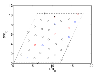
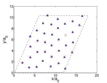
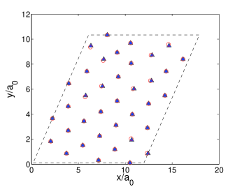
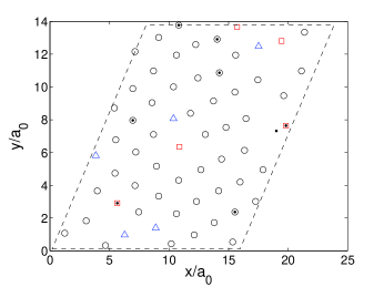
We first address the question of the degree of alignment of the vortices along the tilted columnar pins. In our samples, the pin locations shift in the -direction by spacings of the computational lattice across layers. Therefore, there is a shift of 3 spacings of the computational lattice after every 32 layers. If the vortices are aligned with the columnar pins, then their positions would also shift by 3 spacings of the computational lattice after every 32 layers. We can check whether this happens by showing in the same plot the vortex positions on layers where is an arbitrary integer between 1 and 32 and . To compensate for the expected shift due to the presence of the tilted columns, we shift the vortex positions on layer by spacings of the computational lattice in the negative -direction. Then, the plotted vortex positions after the shifts on all the different layers, , for any should lie on top of one another if the vortices are aligned with the tilted pins. In Fig.1, we show two such plots for two distinct local minima of the free energy at K. As discussed below (see Fig. 6) in detail, these two minima correspond to the BoG (top panel) and BrG (bottom panel) states at a temperature close to the transition temperature at which their free energies cross. We emphasize that each plot shows the vortex positions on 32 different layers, corresponding to , shifted appropriately to compensate for a tilt in the direction of the columnar pins. The dots in the plot are the pin positions. All other symbols are vortex lattice sites, the precise meaning of their shapes and colors is explained below. The vortex positions on these different layers are found to fall directly on top of one another after the shifts in both panels of Fig. 1, so that only one symbol per site can be seen. This observation indicates that the vortices are almost perfectly aligned in the tilt direction.
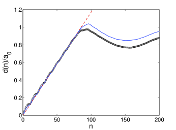
To examine the degree of alignment of the vortices with the tilted pins for other values (not multiples of 32) of layer separation, we consider the quantity which is defined as the average distance between a vortex site and its nearest neighbor in an adjacent plane separated by layers. This is plotted in Fig. 2 as a function the separation between planes for the same BrG and BoG minima and temperature as in Fig. 1. If the vortex lines are perfectly tilted, then, from the geometrical considerations in Sec. II and the numerical values given there, it follows that a plot of vs. should be a straight line with slope for smaller values of . Departure from a straight line is to be expected if exceeds the value for which reaches a value close to , since is (as previously mentioned) approximately half of the average spacing between nearest-neighboring vortices on a layer. This is because for such larger values of , the vortex in layer that has the smallest lateral separation from a vortex on layer is not the one located at a position shifted by in the direction of the tilt from the position of the vortex in layer . Thus, since measures the smallest lateral separation between two vortices located on planes separated by layer spacings, the linear increase of with should be observed only for or . One can see from Fig. 2 that a straight line with the expected slope fits the results perfectly well in the relevant range and this, together with the argument in the previous paragraph shows that as stated in the Introduction, the vortex lines are indeed nearly perfectly tilted along the direction of the pinning columns. This behavior is a consequence of the dominance of the pinning energy over interlayer vortex interactions for the realistic parameter values used in our calculation.
Turning now to the structure in the plane, we have analyzed the structure of the vortex arrangement in each plane by means of a Voronoi construction. A Voronoi construction in any lattice is performed by dividing it into cells, one cell per lattice point, each cell consisting of the region of space which is closest to a certain lattice point than to any other. For a crystalline lattice, this is the Wigner-Seitz cell. In general, the number of sides of the Voronoi cell surrounding a lattice point is the number of neighbors of the lattice point. The Voronoi analysis then reflects directly the defect structure. The use of different symbols in Fig. 1 is meant to show examples of such Voronoi plots for the shifted lattice. We see that from the point of view of the Voronoi construction there is a contrast between the two cases shown, at the same where two phases are locally stable and have approximately the same free energy. The state in the top panel contains a considerable number of defects, as can be seen by the adjacent site pairs with five or seven neighbors, while the state in the bottom panel contains none. Hence the first state can at least tentatively be identified as a BoG state while the phase in the bottom panel, which in the spatial scale of the computation looks like a perfect crystal, can be identified as a BrG with a more ordered structure than the BoG.
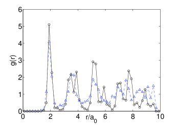
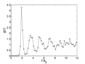
One can alternatively describe the structure and verify the above identifications by studying the density correlation functions. It is straightforward to extract from the vortex positions the in-plane angularly averaged two-point correlation function of the vortex positions, defined as
| (7) |
where if the computational lattice site on layer corresponds to a vortex position (i.e. if the local density peaks at this computational lattice site), and otherwise, is the area of the sample in the -plane, and if the distance between the lattice sites and lies between and (we use in our calculation), and otherwise. The normalization of is such that it should approach unity in the large- limit if there is no long-range translation order in the planes. For a perfect triangular lattice, the first 5 peaks of should occur at , , , and . This is different from the more familiar pair distribution function that measures the two-point correlation of the local density. In particular, information about the degree of localization of the local density peaks corresponding to the vortex positions is not contained in because only the positions of these peaks are used in its calculation. Examples of are plotted in Fig. 3 for the same two cases as in Fig. 1. Again, we see the contrast between the two cases. Although the relatively small size of the system precludes studying the very long behavior, one can see that the correlation function for the state which in Fig. 1 exhibited no defects has a more ordered structure (higher and better defined peaks at the values of for which sharp peaks are expected for a triangular lattice) than the one we tentatively identified as a BoG state based on the Voronoi constructions of Fig. 1. Thus, this analysis if confirms the identifications made based on direct visualization and the Voronoi construction.
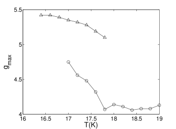
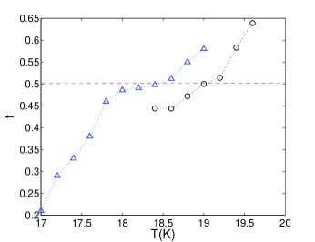
Next, in Figure 4 we consider a measure of the order as a function of temperature. There are a number of ways in which one can define an “order parameter” and here we choose the value of at its first peak. This quantity, which we call , is plotted as a function of for the same configuration presented in the previous figures. We do this for both the BrG phase and the BoG one. As we shall see below in the discussion associated with Fig. 6, the BrG does not exist, even as a metastable, state for and the same holds for the BoG at , hence the ranges plotted. We see that this quantity decreases with in either case but that it is considerably larger in the BrG than in the BoG, as one would expect. At where, as we shall see below, the free energies of the two states cross, there is a marked discontinuity in the equilibrium value of . The nearly constant value of for the BoG phase at temperatures higher than 17.8K is a reflection of the above mentioned fact that the considered here does not take into account the broadening of the local density peaks with increasing temperature.
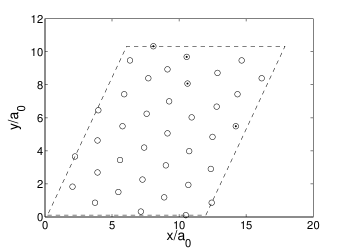
We end this section with a comparison of the structures of the BoG and BrG minima obtained for the same in-plane pin configuration, but for tilted pins in one case and vertical pins in the other case. In Fig. 5, we show vortex position plots similar to those in Fig.1 except that no Voronoi analysis is performed. The top panel shows the data for the BoG phase at K and the bottom panel shows the results for the BrG phase at K. It is clear from these plots that the in-plane structure for tilted and vertical pins are very similar in both the BrG and BoG phases. The degree of alignment with the pins is also found to be very similar for tilted and vertical pins. There are differences, however, between the vertical and tilted cases, as we will see below.
III.2 Free energy and phase transitions
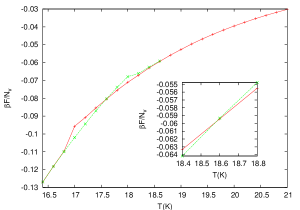
The minimization procedure yields, of course, the value of the free energy at each local minimum. By considering the free energy values as a function of the possible phase transitions in the system can be studied. In Fig. 6 we show typical results at . The main plot is for the tilted case with in which case, as explained above, . The free energy per vortex is plotted as a function of temperature. At high temperatures only one state is stable. The corresponding free energy is plotted as the (red) crosses. By analyzing the results at each as explained in the previous subsection, we find that this state is disordered, a BoG. It exists down to K, where, as one can see in the figure, it becomes unstable to the other state. This other state, the free energy of which is denoted by the (green) signs connected by dotted lines, is found in the same way to be the BrG state. At temperatures in the range both states can be found, one being of course only metastable. The crossing of the free energies occurs at where therefore a first order transition occurs, as seen by the difference in slopes of the free energy and the discontinuity of the order parameter in Fig. 4.
The insert shows, in a reduced temperature range, similar results for the same pin configuration but at (vertical pins). We see that in that case the first order transition occurs near , about one degree higher than in the tilted case. This one degree shift occurs for all pin configurations investigated at this value of : although the values of the individual transition temperatures show some sample-to-sample variation, the one degree shift always occurs. We see then that for increasing the angle leads to a notable decrease of the temperature at which the BrG transforms to the BoG.
At higher temperatures the BoG crosses over to an interstitial liquid phase. As we have seen in the vertical pin caseusprl ; us2 ; us3 this transition coincides with the onset of percolation of the liquid phase. The determination of this transition is shown in Fig. 7. The quantity plotted there is the fraction of the liquid-like local density peaks as a function of temperature. A vortex lattice site is assumed to be liquid-like ifus2 the local value of does not exceed (excluding of course the pinning sites). This fraction of liquid-like sites is small at lower and it rises rapidly up to temperatures higher than the first order transition. Then it flattens somewhat and it crosses the value of (the threshold value for site percolation on a triangular lattice) at a higher temperature K. We take this to be the temperature of crossing over from the BoG to the IL region. In Fig. 7 results are also plotted for the vertical pins case. The percolation crossover is found to occur at a slightly higher temperature, K, for vertical pins.
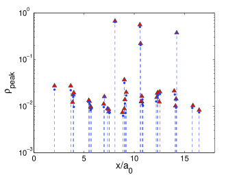
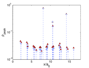
There are some additional noteworthy differences between the tilted pin results and the results for vertical pins. We have already seen that the transition temperatures from BrG to BoG (Fig. 6) and from Bog to IL (Fig. 7) are higher for vertical pins. In the Fig. 6 plots one can also observe that the difference in the slopes at the crossing, which is a measure of the latent heat per vortex, is smaller in the vertical pin case, as compared to the tilted situation. An additional difference is plotted in Fig. 8. There we plot, in a semilog scale, the local density peak height as a function of coordinate in the direction, for both the tilted case (plotted with lines ending with dots) and the vertical one (triangles). This is done in one panel at in the BoG phase and at (BrG) in the other panel. It is striking that in both cases the peak heights for vertical pins are always higher.
The free energy per vortex is somewhat lower (at the same ) in the vertical case at lower values of but the difference becomes negligible at sufficiently high temperatures where the stable state is the BoG in both cases. This occurs, we think, for the following reason: in Fig. 8 and similar data, the integrated vortex densities with values close to unity correspond to pin locations, indicating that the pins are almost fully occupied by vortices. Therefore the portion of the free energy arising from inter-plane electromagnetic interactions will tend to be higher in the tilted case. However, Fig. 8 also shows that the smaller peak densities away from the pinning columns are also higher for vertical pinning columns. This means that the density distribution in the vertical case is more localized, which is consistent with the higher transition temperature. At or above the melting temperature of the pure vortex system without pins, a more localized density distribution will tend to have larger contributions to the free energy arising from entropy and in-plane interactions. At temperatures above the free energy gain arising from the lower localization in the tilted case basically cancels the free energy cost from the inter-plane vortex interaction.
III.3 Results at
We have also studied a somewhat higher concentration, at . This corresponds to a somewhat larger tilt angle, . Results for the obtained equilibrium structure are given in Fig. 9. The top panel of this figure shows the vortex lattice structure along with the results of a Voronoi analysis (completely analogous to Fig. 1). Despite the very low value of the temperature () we find that a good number of defects remain and that the structure is the same as the BoG one in the top panel of Fig. 1. This is confirmed in the bottom panel of Fig. 9 where we plot, at the same , the correlation function as in Fig. 3. We see (compare with Fig. 3) that the correlation function structure is of the BoG type. This remains the situation down to the lowest temperatures reached (). The free energy per vortex is not too different from that in the case (Fig. 5) but no instability to a more ordered state is found, down to the lowest attained. It is possible to obtain BrG like structures by quenching to low temperatures with initial conditions corresponding to a crystal: we have done so by quenching to but the resulting free energy values are considerably higher than those for the BoG at the same . Thus in this case only the BoG is found as an equilibrium state.
We conclude that at these values of and no transition to a BrG occurs except possibly at much lower temperatures. We have also studied the same pin configuration, at this value of , for vertical pins. We have again found no BoG to BrG transition upon cooling. We conclude then that the change in , not the different value of , is responsible for the different behavior found in the two cases studied here. The high sensitivity of the possible BoG to BrG transition to should not come as a surprise. In previous work (see in particular Fig. 1 of Ref. us3, ) for vertical columns and a much larger value of , where because the problem is quasi two-dimensional we were able to map the phase diagram in the plane at constant field, we found that the line in the plane separating the BrG from the BoG, while nearly vertical at small , eventually curves sharply and then becomes nearly horizontal, reflecting a very strong dependence of the transition temperature on and leading in fact to the disappearance of this first order transition at somewhat larger . This is quite consistent with what we find here. There are however small quantitative differences with the results of Ref. us3, . Here, we find that the BrG phase is still present at low temperatures for , whereas Ref. us3, reported this phase absent for . The transition and crossover temperatures found here are also slightly different from the values reported in our earlier work. We believe that this is due to the large difference between the sizes of the systems considered. Since the system with vertical columnar pins is effectively two-dimensional, it was possible to study much larger systems (with , about 100 times larger than those considered here) in our earlier studies. The smallness of the system size in the present study makes the results quantitatively less reliable: this is clear from the observed sample-to-sample variations of the transition and crossover temperatures. Our earlier results obtained for much larger samples, would be more reliable for vertical pins. The purpose of considering vertical pins in the present work was to make a direct comparison with the behavior for tilted columnar pins without having to worry about sample to sample variations or finite size effects.
IV Summary and discussions
Our detailed comparison of the results for the thermodynamic behavior of the vortex system in the presence of a dilute array of tilted columnar pinning centers reveals significant quantitative differences between this system and a smilar system with vertical pinning columns, normal to the layers, in the same in-plane configuration. The thermodynamic behavior of the tilted pins system is however qualitatively similar to that found in our earlier studies usprl ; us2 ; us3 of the vortex system with columnar pins perpendicular to the layers. In both cases, all the pins are occupied by vortices if the relative concentration of the pinning centers is small. In the tilted case, we find that the interstitial vortices are well-aligned in the tilt direction. If the relative pin concentration is low (), the low-temperature phase exhibits the characteristics of a Bragg glass. As the temperature is increased, this phase transforms, via a first order transition, to a more disordered BoG phase which crosses over to an interstitial liquid at a slightly higher temperature. For a higher pin concentration (), the Bragg glass phase is absent and the system exhibits only the crossover from the low-temperature BoG to the interstitial liquid phase as the temperature is increased. This is qualitatively similar to what occurs in the vertical pins case.
Quantitatively, the temperatures at which the transition from the BrG phase to the BoG phase and the crossover from the BoG to the interstitial liquid occur are found to be appreciably higher (by about one degree, or over 5%) in the vertical pin case. The degree of localization of the vortices in the low temperature, solid-like phases is also significantly higher for vertical pins. We attribute these differences to the “frustration” in the tilted case, arising from a competition between the interlayer vortex interaction, which is minimized when the pancake vortices on different layers are stacked in the vertical direction, and the pinning energy which is minimized when the vortices are aligned in the direction of the tilt. This competition also makes the free energy in the tilted case slightly higher than that for vertical pins at low temperatures, as we have seen. These physical effects of tilting the columnar pins away from the layer normal should be observable in experiments.
The differences we find between the results for vertical and tilted pins seem to contradict some experimental zeldov07 studies which concluded that the thermodynamic behavior of the vortex system is independent of the angle between the magnetic field and the tilt direction if the areal densities of pancake vortices and pinning centers on each layer are held fixed. It is important to understand the reasons for this apparent disagreement. In the experiment of Ref. zeldov07, , the effects of changing the angle between the magnetic field and the direction of columnar pins were explored by changing the field direction for a sample with columnar pins tilted by 45∘ from the layer normal. This is not the same as the situation considered in our study. In an isotropic superconductor, the individual directions of the field and the columnar pins are not important: the behavior of the vortex system is determined by the angle between the two directions. But for highly anisotropic layered materials such as high- superconductors, the directions of both the field and the columnar pins are important. The experiment of Ref. zeldov07, did not present any comparison between the results obtained for the two cases considered in our study: one in which the pins are tilted away from the layer normal, and the other in which the pins are perpendicular to the layers, but the areal densities of the pins and pancake vortices on each layer are the same as those in the first case. Since the measurements for different orientations of the field were carried out for the same sample with the columnar pins tilted away from the direction of the layer normal, the frustration effects mentioned above, arising from the competition between interlayer interactions and pinning, were present in all the measurements. In contrast, these frustration effects are not present in one of the cases (vertical pins) considered in our study. Thus there is no real contradiction. In view of our results, an experiment that makes a comparison between the thermodynamic behavior in the two cases considered in our study would be very interesting.
It is more difficult to understand the reason for the difference between our results and those of Langevin simulations zeldov07 ; gl07 performed on systems very similar to those considered in our study. The simulations described in these papers were carried out for both vertical and tilted columnar pins, keeping the areal densities of pinning centers and pancake vortices fixed. Both electromagnetic and Josephson interactions between pancake vortices on different layers were included. Since both these interactions prefer vortices on different layers to stack up in the direction of the layer normal, the frustration arising from the competition between these interactions and the pinning potential for tilted columnar pins is expected to be stronger in these simulations in comparison to that in our study which considers only the electromagnetic interaction. However, these simulations did not find any significant difference between the results for vertical and tilted pins. This disagreement with the results of our study may be a consequence of differences in system parameters. The values of used in the simulations ( and ) are substantially higher that those (1/9 and 1/8) considered here. A large concentration of pinning centers has the effect of reducing the relative importance of the interlayer interactions by making the pinning energy the dominant term in the total energy of the vortex system. In fact, it is argued in Refs. zeldov07, ; gl07, that the cost in Josephson and electromagnetic energies due to the tilting of the vortices is negligibly small compared to the gain in pinning energy for the parameters used in the simulations. If this is so, then it is not surprising that the simulations did not find any difference between the thermodynamic behavior for tilted and vertical pins. It is also possible that the simulations are not sufficiently accurate to capture the fairly small differences between the results for the two cases found in our study. The relatively small size of the simulated systems (, and a number of layers , which is substantially smaller than that considered in our study) implies that there would be large fluctuations in the quantities measured in the simulations. This would lead to substantial uncertainties in the determination of transition temperatures – it is well-known that it is very difficult to determine transition temperatures accurately from simulations of small systems. The authors mention in Ref .gl07, that their simulation is not accurate enough to determine transition temperatures with an accuracy of . Since the differences between the transition and crossover temperatures for tilted and vertical pins found in our study are of the order of , these differences would not be detected in the simulation. Some of the detailed comparisons between the results for the two cases, shown in Fig. 8 of Ref. gl07, , are actually in agreement with our observations. For example, it is shown in panel (c) of Fig. 8 of Ref. gl07, that the mean-square displacement of the vortices from their equilibrium positions is slightly higher in the tilted case. This is very similar to the results shown in Fig. 8 above. We expect that the other differences between the results for vertical and tilted columnar pins found in our study will also be observed in simulations if the measurements are done with sufficient accuracy at the same values of and other relevant parameters.
Acknowledgements.
This work was supported in part by NSF (OISE-0352598) and by DST (India).References
- (1) G. Blatter, M.V. Feigelman, V. B. Geshkenbein, A. I. Larkin, and V. M. Vinokur, Rev. Mod. Phys. 66, 1125 (1994).
- (2) D. R. Nelson and V. M. Vinokur, Phys. Rev. B 48, 13060 (1993).
- (3) L. Radzihovsky, Phys. Rev. Lett. 74, 4923 (1995).
- (4) S. S. Banerjee, S. Goldberg, A. Soibel, Y. Myasoedov, M. Rappaport, E. Zeldov, F. de la Cruz, C. J. van der Beek, M. Konczykowski, T. Tamegai, and V. M. Vinokur, Phys. Rev. Lett. 93, 097002 (2004), and references therein.
- (5) S. Tyagi and Y. Y. Goldschmidt, Phys. Rev. B 67, 214501 (2003).
- (6) Y. Nonomura and X. Hu, Europhys. Lett. 65, 533 (2004).
- (7) C. Dasgupta and O.T. Valls, Phys. Rev. Lett. 91, 127002 (2003).
- (8) C. Dasgupta and O. T. Valls, Phys. Rev. B 69, 214520 (2004).
- (9) C. Dasgupta and O. T. Valls, Phys. Rev. B 72, 094501 (2005).
- (10) T. Nattermann, Phys. Rev. Lett. 64, 2454 (1990).
- (11) T. Giamarchi and P. Le Doussal, Phys. Rev. B 52, 1242 (1995).
- (12) T. Hwa, D. R. Nelson and V. M. Vinokur, Phys. Rev. B 48, 1167 (1993).
- (13) L. Ammor, B. Pignon, N. H. Hong and A. Ruyter, Phys. Rev. B 69, 224511 (2004), and references therein.
- (14) N. Avraham, Y. Y. Goldschmidt, J. T. Liu, M. Myasoedov, M. Rappaport, E. Zeldov, C. J. van der Beek, M. Konczylowski, and T. Tamegai, Phys. Rev. Lett. 99, 087001 (2007).
- (15) Y. Y. Goldschmidt and J. T. Liu, Phys. Rev. B 76, 174508 (2007).
- (16) C. Dasgupta and O.T. Valls, Phys. Rev. B66, 064518 (2002).
- (17) C. Dasgupta and O.T. Valls, Phys. Rev. B74, 184513 (2006).
- (18) C. Dasgupta and O.T. Valls, Phys. Rev. B76, 184309 (2007).
- (19) T. V. Ramakrishnan T.V. and M. Yussouff, Phys. Rev. B 19 (1979).
- (20) J. P. Hansen and I.R. McDonald, Theory of simple liquids, (Academic Press, London, 1986).
- (21) G. I. Menon, C. Dasgupta, H. R. Krishnamurthy, T. V. Ramakrishnan and S. Sengupta, Phys. Rev. B 54, 16192 (1996).
- (22) C. Dasgupta and D. Feinberg Phys. Rev. B57, 11730 (1998).
- (23) C. Dasgupta, Europhysics Lett, 20, 131 (1992).
- (24) Thus, we cannot compare with the different configurations from Ref. us3, , where a much larger was used.