Conoscopic patterns in photonic band gap of cholesteric liquid crystal cells with twist defects
Abstract
We theoretically investigate into the effects of the incidence angles in light transmission of cholesteric liquid crystal two-layer sandwich structures with a twist defect created by rotation of the one layer about the helical axis. The conoscopic images and polarization resolved patterns are obtained for thick layers by computing the intensity and the polarization parameters as a function of the incidence angles. In addition to the defect angle induced rotation of the pictures as a whole, the rings of defect mode resonances are found to shrink to the central point and disappear as the defect twist angle varies from zero to its limiting value and beyond.
pacs:
45.25.Ja, 78.20.Fm, 42.70.Df, 42.25.BsI Introduction
Equilibrium orientational structures in cholesteric liquid crystals (CLC) are represented by helical twisting patterns where molecules on average rotate in a helical fashion about a uniform twist axis. These chirality induced helical structures are responsible for distinctive optical properties of CLCs that have been the subject of intense studies over the last few decades.
It is well known that, similar to one dimensional (1D) photonic crystals, the ideal CLC helix (the planar Grandjean structure) is characterized by a photonic band gap (an optical stop band) where the circular polarized light with the helicity identical to the handedness of the helix cannot propagate and the selective reflection takes place Belyakov:bk:1989 .
In the most studied case of normal incidence, where the light is propagating along the twist axis (the axis) of the CLC helix, which is characterized by the director field, , (the unit vector giving the direction of preferred orientation of CLC molecules) and the CLC pitch, , the Maxwell equations can be solved analytically Belyakov:bk:1992 ; Good:josa:1994 . The well-known result is that the wavelength of light falls between and in the stop band, where and are the ordinary and extraordinary indices, respectively.
Similar to the case of isotropic photonic materials Joannop:bk:2002 , when the one dimensional (1D) periodicity of anisotropic helical structures in CLCs is disrupted, there are a number of physical effects arising due to the presence of localized modes. For instance, in the reflection/transmittance spectral curves of CLCs, the localized modes manifest themselves as peaks and dips that take place for both circular polarizations of incident light and located within the selective reflection band gap.
These modes can be produced within the photonic band gap by a variety of defects such as isotropic defect layers Yang:pre:1999 ; Belyakov:mclc:2008 , twist defects Kopp:prl:2002 ; Kopp:optl:2003 ; Wang:prsa:2005 ; Chen:jpd:2005 , variations of the CLC pitch Stille:epje:2003 ; Ozaki:jap:2006 and local deformations of the CLC helix Matsui:pre:2004 .
Defect modes in CLCs have received much attention because they are known to play the key part in photonic devices such as low-threshold lasers Kopp:prqe:2003 ; Fuh:optex:2004 ; Song:advmat:2006 ; Palto:jetp:2006 and polarization dependent filters Chen:jopa:2005 . But, in the bulk of studies, a major focus of interest is the case of normal incidence where the waves propagate along the helical axis, whereas effects due to oblique incidence (off-axis propagation) have not yet been adequately explored. In the very recent paper Arkhipkin:jetp:2008 , it was found that the defect modes in 1D isotropic photonic crystal with a defect layer represented by a planar oriented nematic liquid crystal film are very sensitive to the variations of the angle of incidence.
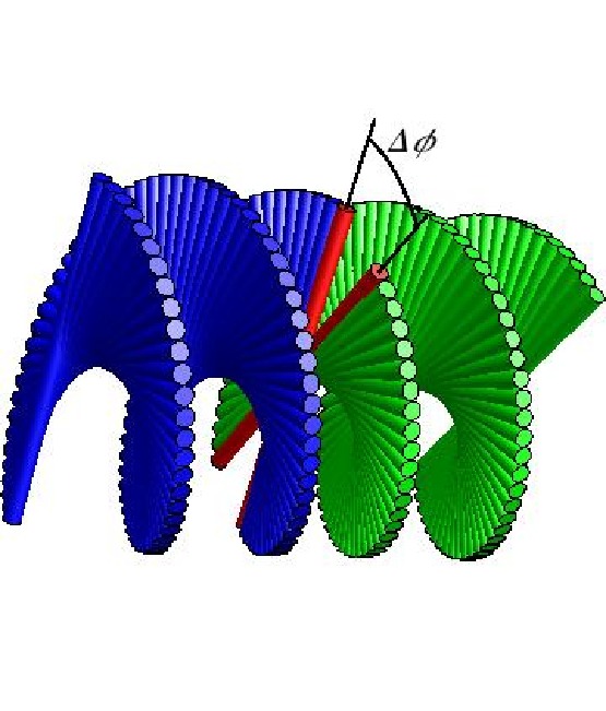
In this Letter we intend to fill the gap and theoretically examine the optical properties of the CLC two-layer sandwich structure with a twist defect created by rotation of the one layer about the helical axis by the defect angle (see Fig. 1). The characteristics of the transmitted light within the photonic band gap at varying incidence angles and polarization of incident wave will be of our primary interest. In particular, we present the results on both the standard conoscopic images (intensity patterns) Bjorknas:lc:2003 ; Song:josa:2008 and the polarization-resolved angular patterns Kis:jpcm:2007 ; Kiselev:pra:2008 .
II CLC layer with twist defect
In our calculations, we assume that the surrounding medium is isotropic and its refractive index is unity (air), whereas the refractive indices of CLC, and , are typical of chirally doped liquid crystal mixtures E7 (commercially available from Merck). The value of the CLC pitch, , where , is taken to be at the centre of the photonic band gap for normally incident irradiation with a He-Ne laser of the wavelength nm.
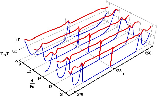
We also restrict ourselves to the symmetric case where the CLC layers are identical in thickness, . According to Refs. Kopp:prl:2002 ; Wang:prsa:2005 , when the thickness changes, the defect modes resonances in the transmission spectra of normally incident light transform giving rise to the crossover phenomenon related to the two limiting structures: peaks and dips that occur in the regimes of thin and thick layers, respectively. This phenomenon is illustrated in Fig. 2a which shows the spectral curves for the diagonal elements of the transmission matrix, and ,
| (1) |
where is the identity matrix; the superscript indicates the matrix transposition; () is the transmission (reflection) matrix of the th layer, linking the circular components of the incident and transmitted light, .
Referring to Fig. 2a, the co-polarized transmission amplitude for right-handed circular polarized light, , undergoes the peak-to-dip transition as the thickness increases reaching the regime of thick cells, where the defect mode manifests itself as the pronounced dip in spectral curves for the coefficient . Since this regime is less studied as compared to the case of thin cells, in this work, it will be of our primary concern. So, we deal with sufficiently thick CLC layers of the thickness m.
Our computational procedure is based on the theoretical approach developed in Refs. Kis:jpcm:2007 ; Kiselev:pra:2008 . In this method, the transfer and reflection matrices, and , are expressed in terms of the evolution operator of the Maxwell’s equations rewritten in the matrix form giving the system for the in-plane components of the electric and magnetic fields combined into the vector : , where and stands for the derivative with respect to . So, the first step involves computing the evolution operator, , as the solution to the initial-value problem
| (2) |
where is the matrix determined by the CLC dielectric tensor, the incidence angle, , and the azimuthal angle of the incidence plane, (the general expression for can be found, e.g., in Kis:jpcm:2007 ; Kiselev:pra:2008 ).
For normally incident light with , it can be shown that the rotating wave ansatz makes the matrix of the system (2) independent of and thus the evolution operator can be found in the closed form. The transmission matrix (1) then can be readily calculated by using the relation for the block structure of the linking matrix Kis:jpcm:2007 ; Kiselev:pra:2008
| (3) |
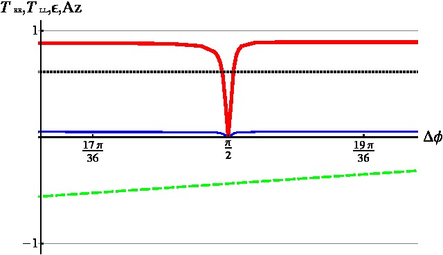
where and is the matrix of eigenvectors for the ambient medium. In Fig. 2a, we used the analytical results to plot the transmission amplitudes, and , in relation to the wavelength, . Dependence of both amplitudes on the defect twist angle depicted in Fig. 2b demonstrates a pronounced dip at . This figure additionally shows the ellipticity, , and polarization azimuth, , of the transmitted wave computed for the left-handed circular polarized incident light, so that and .
As demonstrated in Fig. 2b, in thick CLC cells, the ellipticity remains unchanged, whereas the azimuth varies linearly with the defect angle: . This behaviour results from the fact that, in this regime, the polarization characteristics of the transmitted light are independent of the incident wave polarization. From the analytical expressions (1), it can also be inferred that orientation of the polarization ellipse is determined by the azimuthal angle of the CLC director at the exit face, .
III Results and discussion
The case of oblique incidence (off-axis propagation) with is not exactly solvable and the system (2) has to be solved numerically. In Fig. 3, we present the results of calculations in the form of the traditional intensity conoscopic patterns representing the angular distributions of the co-polarized transmission amplitude in the plane of observation where the polar coordinates, are determined by the incidence angles: and Bjorknas:lc:2003 ; Song:josa:2008 ; Kiselev:pra:2008 . Note that the dominating contribution to the transmittance comes from this amplitude because, as is evident from Fig. 2, .
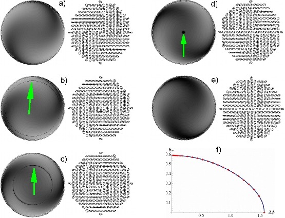
The conoscopic patterns for the defectless sandwich structure with representing the CLC layer of the thickness are shown in Fig. 3a. It is well known that the selective reflection region shifts to shorter wavelengths (blue shift) as the incidence angle increases Bjorknas:lc:2003 . In our case where nm and , the points are found to fall outside the photonic band gap provided the incidence angle is above deg. So, the patterns are computed for the solid angle with deg so as to have the images for the distributions within the photonic band gap.
Without the defect there are several known features Bjorknas:lc:2003 such as Airy spirals that are visible in Fig. 3a. In the corresponding polarization-resolved pattern depicted as the field of polarization ellipses, the ellipticity varies smoothly and its value ranges from to . By contrast, the polarization azimuth undergoes noticeable changes with the azimuthal angle of the incidence plane, , giving rise to the Airy spirals formed due to rotation of the polarizatiion ellipses.
Note that the above discussed case of normal incidence corresponds to the centre of images. Referring to Fig. 3a-e it can be seen that, for the central polarization ellipse, counterclockwise rotation is the only effect caused by the increase in the defect twist angle. Clearly, this effect is in agreement with the results presented in Fig. 2b. Fig. 3a-e show that, as opposed to the central ellipse, the conoscopic images and the polarization resolved patterns as a whole rotate clockwise with the defect angle, .
In addition to the rotation effect, there are defect mode sharp resonance dips in the distribution of the transmission amplitude. These dips form the dark thin rings (circles) which are indicated by arrows in the conoscopic images 3b-d. It can be seen that, at small defect angles, the defect mode ring develops near the band gap edge (see Fig. 3b) and it shrinks to the point located at the origin when the defect angle increases reaching its limiting value deg. (see Fig. 3d). As is shown in Fig. 3e, the defect mode resonances disappear at deg. This effect is additionally illustrated in Fig. 3f where the incidence angle giving the radius of the defect mode ring is plotted against the defect twist angle, . The radius is shown to be a monotonically decreasing function of the defect angle that vanishes at .
By contrast to the intensity conoscopic images, the polarization resolved patterns appear to be insensitive to the presence of the defect mode resonances. So, in these patterns, we have the defect induced rotation as the only significant effect. Note that, for normally incident incoming light, the analogous results on insensitivity of the polarization characteristics immediately follow from the curves shown in Fig. 2b.
So, we may conclude that, in the conoscopic patterns of thick CLC cells with twist defects at varying defect angle, the most important effects are: (a) the defect angle induced rotation of the pictures as a whole and (b) the defect mode ring shrinking to the origin with the defect twist angle.
It should be emphasized that, in thin layers, the patterns are expected to reveal more intricate behaviour as their structure will be complicated by additional interference effects. These results along with the comprehensive theoretical analysis omitted in this work will be published elsewhere.
References
- (1) V. A. Belyakov and V. E. Dmitrienko, Optics of Chiral Liquid Crystals, vol. 13 of Soviet scientific reviews (Harwood Academic Pub., Chur, Switzeland, 1989).
- (2) V. A. Belyakov, Diffraction Optics of Complex Structured Periodic Media (Springer-Verlag, Berlin, 1992).
- (3) R. H. Good and A. Karali, J. Opt. Soc. Am. A 11, 2145 (1994).
- (4) J. D. Joannopoulos, R. D. Meade, and J. M. Winn, Photonic Crystals: Molding the Flow of Light (Princeton Univ. Press, Chichester, 2002).
- (5) Y.-C. Yang, C.-S. Kee, J.-E. Kim, H. Y. Park, J.-C. Lee, and Y.-J. Jeon, Phys. Rev. E 60, 6852 (1999).
- (6) V. A. Belyakov, Mol. Cryst. Liq. Cryst. 494, 127 (2008).
- (7) V. I. Kopp and A. Z. Genack, Phys. Rev. Lett. 89, 033901 (2002).
- (8) V. I. Kopp, R. Bose, and A. Z. Genack, Opt. Lett. 28, 349 (2003).
- (9) F. Wang and A. Lakhtakia, Proc. R. Soc. A 461, 2985 (2005).
- (10) J.-Y. Chen and L.-W. Chen, J. Phys. D: Appl. Phys 38, 1118 (2005).
- (11) J. Schmidtke and W. Stille, Eur. Phys. J. E 12, 553 (2003).
- (12) R. Ozaki, Y. Matsuhisa, H. Yoshida, K. Yoshino, and M. Ozaki, J. Appl. Phys. 100, 023102 (2006).
- (13) T. Matsui, M. Ozaki, and K. Yoshino, Phys. Rev. E 69, 061715 (2004).
- (14) V. I. Kopp, Z.-Q. Zhang, and A. Z. Genack, Progress in Quantum Electronics 27, 369 (2003).
- (15) A. Y.-G. Fuh and T.-H. Lin, Opt. Express 12, 1857 (2004).
- (16) M. H. Song, H. Y. Ha, K. Amemiya, B. Park, Y. Takanishi, K. Ishikawa, J. W. Wu, S. Nishimura, T. Toyooka, and H. Takezoe, Adv. Mater. 18, 193 (2006).
- (17) S. P. Palto, JETP 103, 472 (2006).
- (18) J.-Y. Chen and L.-W. Chen, J. Opt. A: Pure Appl. Opt. 7, 558 (2005).
- (19) V. G. Arkhipkin, V. A. Gunyakov, S. A. Myslivets, V. P. G. dnd V. Ya. Zyryanov, S. Y. Vetrov, and V. F. Shabanov, JETP 106, 388 (2008).
- (20) K. Bjorknas, M. A. Geday, and E. P. Raynes, Liq. Cryst. 30, 889 (2003).
- (21) J.-K. Song, J. K. Vji, and K. Sadashiva, J. Opt. Soc. Am. A 25, 1820 (2008).
- (22) A. D. Kiselev, J. Phys.: Condens. Matter 19, 246102 (2007).
- (23) A. D. Kiselev, R. G. Vovk, R. I. Egorov, and V. G. Chigrinov, Phys. Rev. A 78, 033815 (2008).