Practical Way to Measure Large-Scale 2D Surfaces Using Repositioning on Coordinate-Measuring Machines
Abstract
In many situations it is required to perform an inspection of large flat parts on a coordinate-measuring machine (CMM) when it is impossible to probe all necessary surfaces from one position of the part. Or it is necessary to measure a large part which dimensions exceed the volume of an available CMM. For this purpose one needs to merge the data measured in two different positions of the workpiece into one coordinate system. Though most of geodesic software has out-of-the-box functionality to do that, a lot of popular CMM software lacks it. In this paper a practical approach is described to bring a repositioning functionality into a CMM software. The Calypso metrology software was studied. The proposed inspection method can be used both for the measurements of linear dimensions and location tolerances as common practice in Calypso.
type:
Note1 Introduction
Repositioning on CMMs using reference spheres was first analyzed by M.G. Cox [1]. By designing tapped holes into the workpiece where reference spheres can be attached, measurements from the two positions can be stitched into one coordinate system. A FORTRAN software implementation for that method was provided by Butler, Forbes and Kenward in [2]. But it is too complex for practical everyday usage with proprietary CMM software and requires strong mathematical and programming skills from end users.
Here we propose a practical method to reposition flat parts which does not require any design changes to the part to be made. We will implement it using Calypso metrology software.
For clarity let us start directly with an application of this method and describe the procedure on a concrete example. Imagine a rectangular plate with four in-line holes (fig. 1).
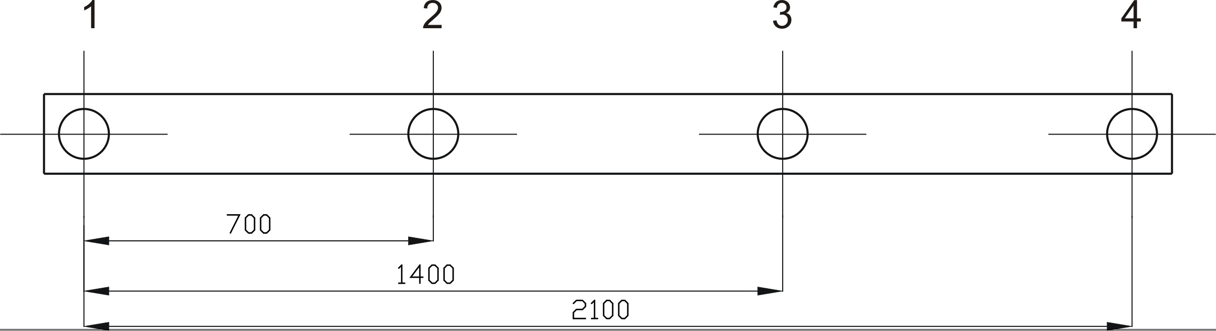
Let us consider it is necessary to measure distances between the center of the first hole and the centers of every other hole. Taking into consideration that measuring range of our particular CMM along the longest axis111We don’t consider diagonal clamping of the part since it requires additional fixtures to be designed. is limited to 1500 mm, it is impossible to do the measurement without moving the part because CMM cannot probe all the holes in one position. Most of the geodesic software can do it [3], [4], but typical CMM software does not have out-of-the-box solution for this task.
We assume that the reader is not only familiar with the Calypso metrology software, but also has some experience with parametric coded measurements: Calypso PCM. For a detailed specification of Calypso please refer to the user guide [5], and for a description of parametric coded measurements see the PCM training manual [6].
2 Manual approach
We have to bring the coordinates of every hole center into one coordinate
system in order to solve the abovementioned problem. For this purpose we
use centers of the holes 2 and 3 as registration points to merge data from
two positions of the part. Initially, we need to
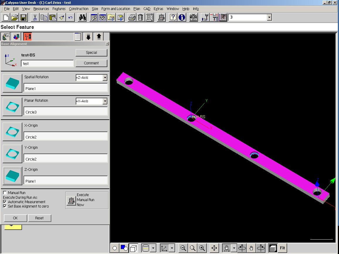
create a Base alignment for the part in Calypso. Let us use the workpiece’s
top plane (plane of the drawing fig. 1) for spatial rotation. We move origin
of the reference frame to the center of hole 2. Hole 3 is used for the
planar rotation to define the direction of X axis. So the Base alignment
looks as follows (fig. 2):
-
•
X axis passes through the centers of the holes 2 and 3, from left to right;
-
•
Z axis is orthogonal to the top plane of the workpiece, pointing to the viewer;
-
•
Y axis is orthogonal to X and Z, pointing down;
-
•
XY planar origin is at the center of hole 2;
-
•
Z planar origin is at the top plane of the workpiece.
Let us put the workpiece inside the CMM measuring range so, that we will be able to measure holes 1, 2 and 3 directly. This is possible considering the CMM measuring range is limited to 1500 mm.
We can measure the first three holes in CNC mode. We have to exclude the fourth holes from CNC run by manually selecting only the features related to the first three holes (BaseAlignment and Position1 groups) and specifying “Current Selection” before CNC start. After this measurement we write down the coordinates of the first hole into a notepad — we will need them later.
Now we are ready to reposition the workpiece and measure the fourth hole. First, let us move the workpiece so that the holes 2, 3 and 4 become accessible by the probing system. Exclude hole 1 from measurement (by selection of BaseAlignment and Position2 groups) and restart CNC run with manual alignment. After alignment is done the fourth hole is measured in CNC mode.
Unfortunately, Calypso purged the measured coordinates of the feature “Circle1”. But we can easily restore them222Since the stored coordinates are in Base Alignment we don’t need to perform any additional transformations. from the notepad and place into a theoretical feature (Circle1’).
We can now use the created theoretical feature to create all the characteristics we need to determine the required distances. Calypso evaluates them as if all the measurements had been done in one measurement run.
This method successfully measures almost any flat workpiece, in which the number of features for realignment is one or two.
3 PCM approach
If there are a lot of features to be converted from one alignment to another the amount of manual work will be incredibly large and the manual approach described above becomes impractical. Besides, the manual stage of the method is prone to operator’s errors. It is a good idea to make the realignment process fully-automatic.
We can use Calypso’s parametric coded measurement functionality333Users without the Calypso PCM option will be unable to perform actions described in this section. to pass the results between two alignments. The general workflow remains the same; the only difference is that we use a disk file instead of a notepad. We write and read data to and from this file using a tiny PCM program.
Three following functions from the Calypso PCM programming
language are necessary to meet our demands for file access:
-
•
deleteFile( ”file name” ) — delete a file
-
•
addToFile( ”file name”, ”text line” ) — add a line to a text file; if the file does not exist it will be created
-
•
readPCMFile( ”file name” ) — read values of PCM variables from a text file into Calypso444Those familiar with C/C++ programming languages will find it similiar to include-files..
The operational sequence of our PCM program will be as follows: delete the file during the first CNC run and write the coordinates of the first hole into it; read the file during the second CNC run and apply the stored values to a theoretical feature. First and second CNC runs refer to first and second position of the workpiece respectively.
The PCM program to be executed after the first CNC run is:
   deleteFile( "C:\TempFile.param" )

   XStr = format(getActual("Circle1").x)
   YStr = format(getActual("Circle1").y)

   PosXStr = "PositionX = " + XStr
   PosYStr = "PositionY = " + YStr

   addToFile( "C:\TempFile.param", PosXStr )
   addToFile( "C:\TempFile.param", PosYStr )
Content of the temporary file after this run is:
   PositionX = -699.9657d
   PositionY = -0.0138d
The PCM program to be executed before the second CNC run is simpler and consists of the only line:
readPCMFile( "C:\TempFile.param" )
We have to use variables PositionX and PositionY as an X and Y parameters of the theoretical feature Circle1’ respectively. Finally the manual part of the work has been eliminated — all the reading now is done automatically.
4 Registration points
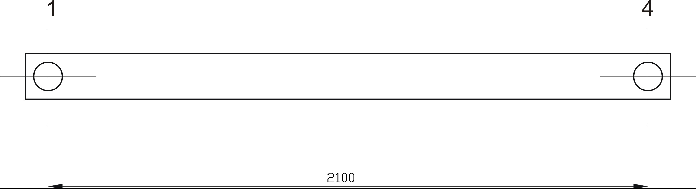
In some workpieces there are no features that can be used for registration points (same way like holes 2 and 3 were used). An example for such a workpiece can be obtained by a simple modification of our original sketch (fig. 3).
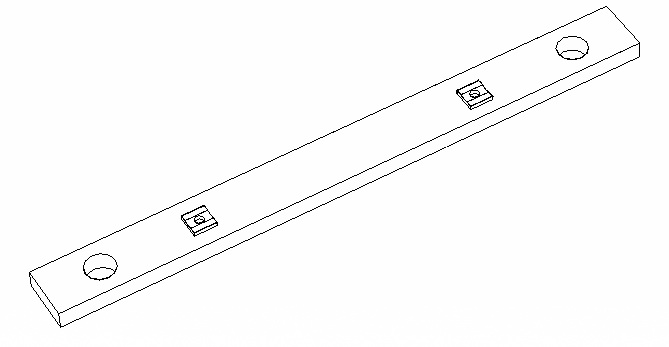
Artificial registration points should be created to overcome that difficulty. Cox [1] suggests usage of zirconium spheres for this purpose. In case of flat parts a simple artifact can be used (fig. 4).
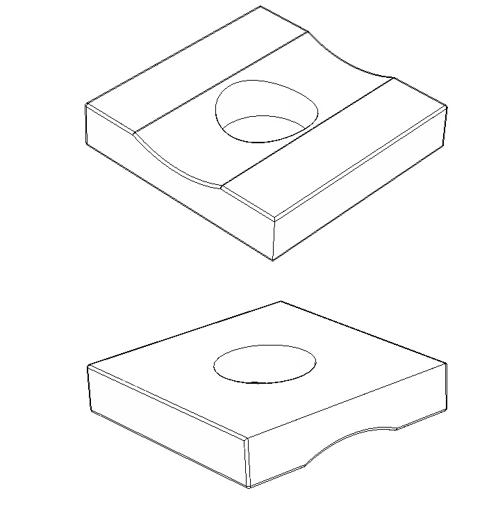
Two of these plates can be attached (i.e. glued or clamped) to the most of planar or radial surfaces of a workpiece to create an artificial datum which moves rigidly with the workpiece, i.e. as in fig. 5. Two-sided scotch tape can be efficiently used as a fixture if uncertainty of 0.01 mm is enough.
The distance between the two plates on the workpiece should be kept maximal (it is limited to the size of the workpiece and the measuring range of CMM) to prevent creation of a degenerate datum. Both plates should actually remain intact during both CNC runs. This solution allows complex parts with freeform surfaces and without any regular geometry features to be measured.
5 Reliability of the method
Though we do not know how to obtain reliable uncertainty estimates from Calypso, it is easy to see that our procedure does not introduce significant additional errors. Indeed, we can check it by means of comparison. We measured a small block with holes, similar to that at fig. 1, but its length was only 100 mm. It was measured with and without repositioning. Deviation of these two results was within 0.01 mm555Cox claims [1] that in the “step gauge experiment” using ten zirconia reference spheres with sphericity the maximum standart uncertainty of was achived.. Each result was obtained by 10 measurements on the Carl Zeiss Prismo 10 S-ACC with = .
The author will appreciate any third party help or ideas, especially ones from developers of the Calypso software, to move this experiment to a good theoretical ground. See [7] for an in-depth assessment of the evaluation of coordinate-measuring machines uncertainties.
6 Limitations
Since two points on a plane define rotation and planar origin, the proposed method can be applied directly only to the planar repositioning of workpieces. To do three dimensional repositioning at least three registration points should be used. Reference spheres [1] or cylinders will be preferable for this task instead of plates (fig. 4). Spheres also can be probed from any direction and cylindrical holes only from a direction parallel to their axis. Repositioning with the usage of reference spheres in Calypso can be automated the same way.
Nevertheless, the described method of repositioning is significantly simpler and does not require any design changes to be done. Also it is possible to take advantage of available features on a part to create an intermediate datum.
7 Conclusions
It is easy to pass any number of parameters from one alignment to another using the proposed method. The number of alignments is not constrained by two and can be as high as required to fulfill the measurement task completely. Coordinates, saved to the file, are in Base alignment. They can be loaded from file at any time after the original base alignment was changed due to repositioning of the workpiece.
The author was able to measure radii of large circular parts using this method. Dimensions of the parts were large enough to prevent them from arranging inside the CMM volume. It would be impossible to perform this measurement on the available CMM without using the proposed method.
Application of this method is not limited to the flat large-scale parts only. It can be applied to small ones if such parts have complex surfaces and require repositioning to be measured. No design changes to the parts are required.
The PCM approach is very easy to implement and it could be efficiently used as common practice in Calypso measurements.
References
References
- [1] M. Cox, “Measurement of artefacts using repositioning methods,” NPL, Tech. Rep. CLM2, November 1997.
- [2] B. Butler, A. Forbes, and P. Kenward, “Position calibration software: Fortran implementation of algorithms to determine frame of reference from measurements of registration points,” CISE, vol. 14, February 1998.
- [3] AXYZ - Mathematics for Users. Product documentation, Leica Geosystems AG, November 1997.
- [4] AXYZ Software, Integration, Processes and Scripting. Renton WA: Boeing Laser Tracker Seminar, January 1997.
- [5] Calypso Metrology Software. User Guide. Rev.4.0, Carl Zeiss IMT GmbH, 2004.
- [6] Schulungsunterlage Calypso PCM 3.8, Carl Zeiss IMT GmbH, 2003.
- [7] Guide to the Expression of Uncertainty in Measurement. BIPM, IEC, IFCC, ISO, IUPAC and OIML, 1995, second Edition.