Direct Numerical Confirmation of Pinning Induced Sign Change in Superconducting Hall Effect in Type-II Superconductors
Abstract
Using the time-dependent Ginzburg-Landau equation with the complex relaxation time and the Maxwell equation, we systematically examine transverse motion of vortex dynamics in the presence of pinning disorders. Consequently, in a plastic flow phase in which moving and pinned vortices coexist, we find that the Hall voltage generally changes its sign. The origin of the sign change is ascribed to a fact that moving vortices are strongly drifted by circular current of pinned vortices and the enforced transverse moving direction becomes opposite to that by transport current. This suggests that the Hall sign change is a behavior common in all disordered type-II superconductors.
pacs:
74.25.Qt, 74.20.De, 74.25.Fy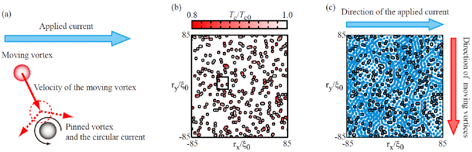
Since the discovery of cuprate high- superconductors, much attention has been devoted to vortex dynamics in not only superconductors but also various superfluids from liquid Helium to atomic gas. In particular, vortex pinning dynamics under disorders inevitable in superconducting materials is a central issue of vortex physics because of deep relations to its industrial applications. In this paper, we numerically examine the vortex pinning dynamics and give a clear explanation to a controversial topic in vortex physics, i.e., sign change in the superconducting Hall effect hagen ; matsuda ; nagaoka ; kokubo ; ping-ao .
The equation of motion for a moving vortex in superfluids has been highly controversial ping-ao . The heart of the problem is the non-dissipative transverse force (or the vortex velocity part of Magnus force) volovik96 ; ao-kopnin-prlcomrep ; hall-wexler-prlcomrep ; zhu , which brings about the superconducting Hall effect. In BCS superfluids, the transverse component is generally subtle, and therefore, various theoretical proposals remain unexamined fully. Among those theories, one of the most controversial struggles is whether pinning or disorder can be an origin of the sign change in the superconducting Hall effect vinokur-1993 ; wang ; ao-1998 ; kopnin-1999 ; ikeda ; b-y-zhu ; ghenim . If it is true, it then indicates that the sign reversal is not limited in particular superconductors, but universal for all disordered type-II superconductors. In this paper, we clarify that the idea is really true by numerically solving the time-dependent Ginzburg-Landau (TDGL) equation with complex relaxation time and the Maxwell equation. This is a direct and clear confirmation of the pinning induced sign change without simplification and modeling.
The vortex dynamical phases under disorders are roughly classified into two types, i.e., plastic and collective flow phases olson . In the former phase, moving and pinned stationary vortices coexist. Then, it is found that moving vortices are strongly drifted by the circular current of pinned vortices and its inducing transverse moving-direction can become opposite to that by transport current. Such a feature is schematically displayed in Fig. 1(a). Thus, the averaged transverse moving direction in the plastic flow phase can be different from that in the collective one. This is an origin of the Hall sign change confirmed in this paper.
Let us present the system setup to confirm the pinning induced sign change. We prepare a two dimensional system in the plane. The external magnetic field is applied perpendicular to the plane. To simulate vortex dynamics, we numerically solve the the TDGL equation coupled with the Maxwell one written as kato ; machida ; crabtree ; nakai08
| (1) | |||||
| (2) | |||||
Here, we introduce local suppressions of the transition temperature , which act as vortex pinning sites. The order parameter is normalized by its mean field value at the zero temperature without the magnetic field, , and time , vector potential , and magnetic field are done by , , and , respectively, where , , , , and are the zero-temperature coherence length, the Ginzburg-Landau parameter, the normal-state longitudinal conductance, the light velocity, and the flux quantum, respectively. To keep the gauge invariance of Eqs. (1) and (2) on numerical grids, we use the link variable , where stands for or kato ; machida ; crabtree ; nakai08 . The magnetic field is given by the Stokes’ theorem , and the electric field is calculated by , where is the unit plaquette surrounded by link variables. We evaluate the longitudinal and the Hall voltage from . In order to concentrate on the vortex contribution to the Hall voltage, we neglect the normal-state Hall conductivity in Eq. (2) for clarity. Instead, the dimensionless relaxation rate in Eq. (1) is set to a complex number. According to Ref. dorsey , is related to the forces acting on each moving vortex. If we set pure real, the transverse force and the resulting Hall voltage are zero. On the other hand, a finite imaginary part of brings about a transverse force, and the sign of the imaginary part controls the sign of the Hall effect dorsey ; fukuyama ; kopnin-TDGL ; aronov ; matsuda . We keep the imaginary part positive and never change its value throughout this study, i.e., the transverse force is always positive and unchanged. Under the condition of the fixed complex relaxation rate, we find that the Hall voltage amplitude diminishes and a sign reversal occurs in the plastic flow regime owing to moving vortices affected by the circular current around pinned vortices.
In the present simulation, the system size is , which is discretized by the square grid whose unit dimension is . The external current is applied along the direction, and a periodic boundary condition is imposed in this direction to eliminate edge boundary effects on the vortex motion. The remaining boundary edge perpendicular to the direction relevant to vortex entry and escape is modeled as an interface between a superconductor and a normal metal. Around this interface, is set , where is the distance from the interface and is the bulk value of . The number of vortex pinning centers is 500 inside the present system . The size of each pinning center is , inside which is randomly suppressed in the range . The locations of pinning centers are randomly distributed, e.g., as shown in Fig. 1(b).
In the TDGL dynamical simulation, we prepare an initial state in the absence of both the applied current and external field, and then start to apply a current and a target external field at . The applied current density is always set as , where is the depairing current. The GL parameter is , and the minimal time step is . We fix , which leads to a substantial ratio of the Hall voltage to the longitudinal one , i.e., , in the uniform current under no pinnings. Such a large imaginary value can give a striking contrast in the sign change of the Hall voltage. To avoid counting an interface influence on the voltage, e.g., an effect of the diamagnetic current, we take an average of the electric field within the region . The time average of the Hall voltage is taken over the time interval , during which vortex motions are steady.
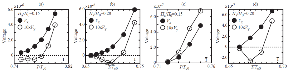
Let us present simulation results. First, the temperature () dependences of the longitudinal and Hall voltages under the applied fields and are displayed in Figs. 2(a) and 2(b), respectively. The longitudinal voltage monotonically decreases with decreasing in both cases. Although the Hall voltage exhibits non-monotonic behavior, both the signs become negative in the region of the small longitudinal voltage . Here, one might imagine that this negative transverse voltage occurs because of guided vortex flow lines kopnin-1999 formed accidentally by clustering of pinned sites. However, it is not always the case. In order to confirm it, we repeat the simulation by just reversing the magnetic field direction only. While the sign reversal disappears for the field (Fig. 2(c)), it is kept for another field (Fig. 2(d)). This suggests that there must be an intrinsic origin of the sign reversal beyond the guiding effects. We further perform simulations (not shown) under other random vortex-pinning distributions (II)–(IV) and repeat the simulations with the field direction reversal ()–(). These results are summarized in Table I. The guiding vortex flow state is found to indeed cause the sign change under the distributions II and III, because the Hall sign does not change on the field inversion cases in both II and III. However, the sign reversal is kept on the field direction reversal for the other distributions I and IV. From these results, it is deduced that the intrinsic sign reversal effect always coexists with the guiding one in the plastic flow phase. One naturally expects that the intrinsic mechanism dominates in sufficiently large samples. The following analysis attributes the intrinsic mechanism to an effect of the circular currents around pinned vortices.
| I | II | III | IV | ||||||
|---|---|---|---|---|---|---|---|---|---|
| Y | N | Y | N | N | Y | Y | Y | ||
| Y | Y | Y | N | N | Y | Y | Y |
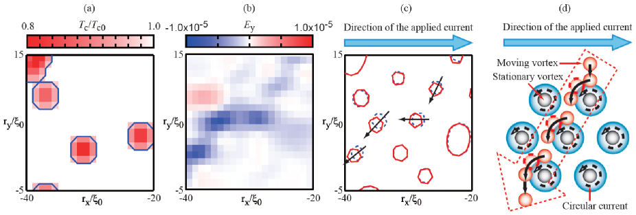
Let us focus on detailed vortex dynamics around vortex-pinning sites. Figure 3(a) is an enlarged figure of a small area whose location is marked in Fig. 1(b). The distribution of the transverse electric field averaged over is shown in Fig. 3(b), where the sign of the transverse field is negative near the vortex pining sites. In addition, by monitoring the vortex position at and in the displayed area, the focused vortices are found to flow against the applied transport current [Fig. 3(c)]. These observed results signify the following. The pinned vortex has a circular current flow around its core. The flow direction is opposite to that of the transport current in its top half as schematically shown in Fig. 3(d), where locally the Lorentz force (or the superfluid velocity part of Magnus force) is directed from bottom to top. Then, the moving vortex penetrating into the circular-current flow range is drifted into the opposite direction to the transport current. This is because the positive imaginary part of fixed in this paper always drives the moving vortex into the downstream side of the current flow as usual. Thus, the moving vortex exhibits a motion directed opposite to the transport current.
Finally, let us discuss the present results through a comparison with experiments. The present calculations have revealed that when the vortex dynamics change from the collective flow to the plastic flow phase the moving vortex frequently reverses its transverse moving direction. This directional reversal principally requires the plastic flow phase as a vortex dynamical phase. In other words, this effect is universal for all type-II superconductors as long as disorders or pinning sites enough to keep the plastic flow phase are introduced inside the sample. In high- cuprate superconductors, double sign change in addition to single one have been frequently observed depending on the sample double-sign-change . These experimental results can be explained on the basis of the present result as follows. When the current carrying phase changes from the normal to the flux flow phase, the first sign change occurs. This can be interpreted by an idea that there is a difference between the Hall effect in the normal phase and the fluctuation Hall effect near the superconducting transition via the relaxation of the order parameter matsuda ; dorsey ; fukuyama ; kopnin-TDGL ; aronov . This is a microscopic sign change mechanism depending on the electronic structure. On the other hand, it has been observed that the final reversals strongly depend on the sample quality or the rate of artificial damage to enrich pinning centers artificial damage . Thus, the final sign change is attributed to the pinning induced one as confirmed by the present simulation. Moreover, such a sign change is also well-known to be sensitively dependent on the sample quality in conventional type-II superconductors.
In conclusion, we performed TDGL simulations with the complex relaxation time to confirm the pinning induced sign reversal of the superconducting Hall effect. Consequently, the simulation revealed that the sign change can occur when the current carrying state enters the plastic flow phase from the collective flux flow one. Moreover, the detailed analysis on the vortex motions successfully explained that, when the circular current of the pinned vortex strongly drifts the moving vortex in the plastic flow phase, the moving vortex feels the transverse force causing the Hall sign change. These results suggest that the Hall sign change is an indicator of vortex dynamical phases in disordered type-II superconductors.
References
- (1) S. J. Hagen et al., Phys. Rev. B 47, 1064 (1993).
- (2) Y. Matsuda et al., Phys. Rev. B 52, R15749 (1995).
- (3) T. Nagaoka et al., Phys. Rev. Lett. 80, 3594 (1998).
- (4) N. Kokubo et al., Phys. Rev. B 64, 014507 (2001).
- (5) P. Ao, arXiv:cond-mat/0404009; arXiv:cond-mat/0407007; arXiv:cond-mat/0504222; arXiv:cond-mat/0610753; arXiv:0706.2650; and references therein.
- (6) G. E. Volovik, Phys. Rev. Lett. 77, 4687 (1996).
- (7) P. Ao, Phys. Rev. Lett. 80, 5025 (1998); N. B. Kopnin and G. E. Volovik, Phys. Rev. Lett. 80, 5026 (1998).
- (8) H. E. Hall and J. R. Hook, Phys. Rev. Lett. 80, 4356 (1998); C. Wexler et al., Phys. Rev. Lett. 80, 4357 (1998).
- (9) X.-M. Zhu et al., Phys. Rev. Lett. 78, 122 (1997); K. Mochizuki et al., Physica C 388-389, 705 (2003).
- (10) V. M. Vinokur et al., Phys. Rev. Lett. 71, 1242 (1993).
- (11) Z. D. Wang et al., Phys. Rev. Lett. 72, 3875 (1994).
- (12) P. Ao, J. Phys.: Condens. Matt. 10, L677 (1998).
- (13) N. B. Kopnin and V. M. Vinokur, Phys. Rev. Lett. 83, 4864 (1999).
- (14) R. Ikeda, Physica C 316, 189 (1999).
- (15) B. Y. Zhu et al., Phys. Rev. B 60, 3080 (1999).
- (16) L. Ghenim et al., Phys. Rev. B 69, 064513 (2004).
- (17) C. J. Olson et al., Phys. Rev. Lett. 81, 3757 (1998).
- (18) R. Kato et al., Phys. Rev. B 47, 8016 (1993).
- (19) M. Machida and H. Kaburaki, Phys. Rev. Lett. 75, 3178 (1995).
- (20) G. W. Crabtree et al., Phys. Rev. B 61, 1446 (2000).
- (21) N. Nakai et al., Physica C 468, 1270 (2008).
- (22) A. T. Dorsey, Phys. Rev. B 46, 8376 (1992).
- (23) H. Fukuyama et al., Prog. Theor. Phys. 46, 1028 (1971).
- (24) N. B. Kopnin et al., J. Low Temp. Phys. 90, 1 (1993).
- (25) A. G. Aronov et al., Phys. Rev. B 51, 3880 (1995).
- (26) W. Göb et al., Phys. Rev. B 62, 9780 (2000), and references therein.
- (27) See Table I in Ref. hagen . Two limiting cases of the dirty and clean does not show the sign change of the Hall voltage in V and Nb.