Broad-band polarization-independent absorption of electromagnetic waves by an overdense plasma
Abstract
Surface plasmon-polaritons can be efficiently excited on a plasma-vacuum interface by an electromagnetic wave when a subwavelength diffraction grating is placed in front of the plasma boundary. The excitation efficiency depends strongly on the wave frequency (or plasma density, when the frequency is fixed) and polarization. We show both experimentally and theoretically that this sensitivity can be essentially suppressed. A non-zero angle of incidence and an axially-symmetric diffraction grating ensure near-total absorption of the incident wave in a broad range of wave frequencies (or plasma densities, when the frequency is fixed). Direct detection of surface plasmon-polaritons has been achieved for the first time using a miniature antenna imbedded in the plasma. A new absorption mechanism which is not associated with surface plasma waves excitation is revealed.
pacs:
52.40.Db, 73.20.Mf, 42.25.FxI Introduction
Surface plasma waves – surface plasmon-polaritons (SPP) – discovered more than fifty years ago Ritchie , are now attracting an increased attention due to their numerous realized or promising applications. Intensive investigations of SPP in the optical frequency range have led to appearance of a new field of physics – plasmonics Zia ; Ozbay . Resonant excitation of SPP is responsible for such effects as the extraordinary transparency of optically thick perforated metal films Ebbesen , resonant transmission of electromagnetic waves through overdense-plasma structures Sternberg , frustrated total internal reflection Otto ; Kretschmann , and superresolution of Veselago-Pendry’s “perfect” lens Veselago ; Pendry ; Ruppin .
A freely propagating electromagnetic wave cannot excite SPP because of the mismatch between their phase velocities along the medium-vacuum interface. The coupling between the electromagnetic wave and SPP can be achieved either in the total internal reflection configuration Otto ; Kretschmann or due to the interface corrugation (periodic, random corrugation, film perforation, etc.). It is worth to notice that it is a question of propagating surface waves. Localized (non-propagating) plasmon-polaritons can be excited by an electromagnetic wave on the surface of subwavelength-size objects Pillai ; Teperik .
Both these methods are acceptable when SPP are excited at a metal interface, and are difficult for realization for SPP excitation at a plasma interface. In the latter case the most convenient is the use of a subwavelength diffraction grating as a matching element Bliokh_1 ; Bliokh_opt ; Tripathi . It has been shown both theoretically and experimentally in Bliokh_1 that the SPP excitation with the use of the diffraction grating properly placed in front of the plasma surface leads to total absorption of the incident electromagnetic wave by an overdense plasma, i.e. by a plasma whose Langmuir frequency, , exceeds the wave frequency . This effect has been observed in a plasma with other parameters Plasma ; Chen and in a solid state plasma Solid .
Due to its resonant nature, the SPP excitation is possible in a relatively narrow range of parameters (plasma density, wave frequency and polarization, angle of incidence, etc.). This property may be utilized in a set of applications such as frequency and angle-resolved filters, for example. On the contrary, other problems like, for example, plasma heating, development of a non-reflecting coating, and enhancement of photovoltaic cells efficiency, need broadening of the parameters region where SPP are effectively excited. Here, we propose and study both theoretically and experimentally some methods of the parameters region broadening. The operation in the microwave frequency range allowed us to achieve (for the first time, as far as we know) direct detection of surface plasma waves by a miniature antenna imbedded in the plasma. It is also shown that the total absorption of an electromagnetic wave by an overdense plasma can also be achieved without SPP excitation.
II Physical background
The phase velocity of SPP propagating along the plasma-vacuum interface is smaller than the speed of light , whereas the projection of the incident wave phase velocity on the interface plane, (where is the angle of incidence), exceeds the speed of light. This mismatch makes impossible direct excitation of SPP by a freely propagating electromagnetic wave.
When a diffraction grating is placed in front of the plasma surface, the scattered electromagnetic field becomes richer by new spatial harmonics whose wave vectors are , where is the grating reciprocal vector, is the incident wave vector, , and . Some of these harmonics can be in resonance with SPP and excite them when the following resonance condition is satisfied:
| (1) |
where is the plasma density, is the plasma permittivity, is the plasma Langmuir frequency, is the wave vector of SPP whose frequency is , and is the tangential component of wave vector . If the incident wave frequency and the angle of incidence are fixed, equation (1) determines the resonant plasma density . The resonant plasma densities (below we will consider the strongest, , harmonics only) are given by the following relation:
| (2) |
where is the critical density defined by the condition .
Besides the resonance condition (1), the incident wave must be properly polarized. Decomposing an arbitrarily polarized incident wave into two linearly polarized waves whose magnetic fields have tangential projections directed along and perpendicular to the grating strips (wave-1 and wave-2 thereafter), one can see that only wave-1 being scattered on the grating excites SPP when the resonant condition (1) is satisfied.
The SPP electromagnetic fields are concentrated in the vicinity of the plasma-vacuum interface and can be much stronger than the incident wave fields. Due to this enhancement of the electromagnetic energy density, even small dissipation in the plasma can lead to a significant absorption of the incident wave energy. In this case electromagnetic wave reflection from the grating-plasma system is small or even equal to zero. The reflection coefficient drops to zero, , under certain conditions which can be easily understood considering a surface wave as a resonator Bliokh_1 ; Bliokh_2 . The Q-factor of this resonator, as the Q-factor of any resonator, is determined by two factors: dissipative and radiative losses. The first one is connected with all kinds of dissipative processes (collisions in plasma, ohmic losses in the grating, etc.). The second one is determined by the efficiency of the transformation of the surface (evanescent) wave into the freely propagating wave under scattering on the grating. These losses are characterized by corresponding Q-factors, and . When both Q-factors are equal one another, , the reflection coefficient vanishes. This phenomenon is well-known in microwave electronics as critical coupling (see, e.g., Slater ; Adler ).
Due to the resonant nature of this phenomenon, the reflection is small either in a narrow frequency band near the resonant frequency (when the plasma density and the angle of incidence are fixed) or in a narrow region of the plasma density values (when the wave frequency and the angle of incidence are fixed). Using equation (1) it is easy to calculate when is known and vice versa. Taking into account the experimental conditions (fixed and , and varying ) we will consider as the resonance width.
Thus, the SPP excitation is sensitive to the deviation of the system parameters from their resonant values as well as to the relative polarization of the incident wave with respect to the grating. There is a set of problems where this sensitivity plays a positive role and can be utilized, for instance, as frequency, angular or polarization filters. On the other hand, the set of applications such as electromagnetic cloaking Alu ; Alitalo , solar cells Pillai ; Akimov , etc., needs suppression of this sensitivity.
The resonance can be broadened in the following way. Under a normal incidence on a 1D grating (grating that is characterized by one vector ) the electromagnetic wave excites two equal SPPs propagating in opposite directions. The resonant plasma density is the same for both SPPs. Strong absorption is observed in a certain region around . If the angle of incidence deviates from zero, two SPPs, whose wave vectors are , can be excited. Now there are two different resonant plasma densities, , and the reflection is suppressed in the regions around them (when the plasma density is fixed, there are two frequency bands for which reflectivity is suppressed). When the difference between the two resonant densities is of the order of the widths , the resonances overlap and the resulting resonant region is broadened.
The above-mentioned sensitivity of the SPP excitation to the incident wave polarization can be suppressed when the 1D grating is replaced by a 2D grating. It can be a periodic grating which is characterized by two mutually orthogonal reciprocal vectors and . If the lengths of these vectors are close to one another, , two components of the incident wave, wave-1 and wave-2, excite surface plasmon-polaritons simultaneously and the reflection coefficient can be small independently of the wave polarization Popov . More complex aperiodic gratings characterized by many reciprocal vectors can also be used Matsui . When the angle of incidence is not equal to zero but small, , every resonance splits into two ones. Overlapping of these resonances can lead to the broadening of the parameters region where reflection is suppressed.
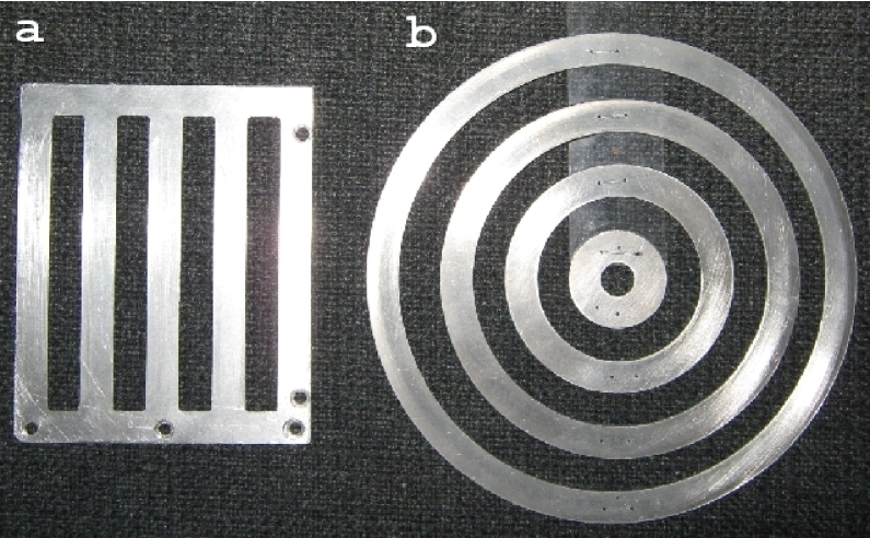
In order to eliminate a priori the dependence on the polarization for normally incident wave we suggest a circular diffraction grating as depicted in figure 1. A qualitative argument for this choice is the following. When the grating radius is large as compared with the wavelength , , the grating can be characterized by a local grating vector , whose length is constant and its direction depends on the polar angle . The local efficiency of the surface wave excitation by a linearly polarized incident wave depends on the angle between the local grating vector and the tangential component of the wave electric field, . There are regions where the efficiency is small or even equal to zero. Reflection from these regions is large and all the energy of the incident wave cannot be absorbed by the plasma. However, when the grating radius does not exceed several wavelengths, this conclusion is not valid. The reason is that the conception of the local characteristics of the grating is applicable to regions whose dimension is comparable with the wavelength and is small as compared with the grating dimension. When the grating dimension is not so large, the grating surface cannot be separated into regions with low and high efficiency . In this case the whole grating is characterized by a unified efficiency and a wave beam focused on the grating can be totally absorbed independently of polarization. When the angle of incidence is not equal to zero but small, , the dependence on the wave polarization is strongly suppressed. It is possible to suppose that a wide wave beam can be absorbed using a superlattice composed of circular gratings.
All the above-mentioned statements related to the resonance broadening and polarization-independent efficiency of the electromagnetic wave absorption have been verified experimentally and results of the experiments are presented in the following sections.
III Experimental results
III.1 Experimental setup
A sketch of the experimental setup is shown in figure 2.
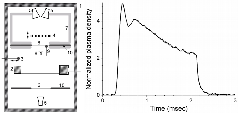
A uniform 20 cm diameter plasma “dish” was formed by a ferromagnetic inductively coupled plasma source, driven by a pulsed (2 ms) 10 kW rf oscillator (not shown in the sketch). The plasma appeared between planar plasma forming plates (PFP). The plasma parameters (density and electron temperature ) were measured by movable and surface Langmuir probes. All the probe measurements were verified by the microwave cut-off method which provides low tolerance (%) of the density measurements. For more details on the plasma source and plasma parameter measurements see Plasma_Ex . The experiments were carried out in a vacuum chamber of 1.2 m length and 0.7 m diameter filled with Xe gas in the pressure range (0.7 - 2.4) mTorr. The electron temperature was found to be (2 - 4) eV. As a microwave source we used a klystron oscillator whose operating frequency was 8.45 GHz (wavelength cm). The plasma density in the vicinity of the PFP decreases monotonically during the pulse from to . The characteristic waveform of the plasma density variation is depicted in figure 2. In the center of each PFP there was made a rectangular ( cm) window of thin (0.1 mm) plastic film providing negligible microwave reflection. The transmitting microwave horn and the one receiving the reflected signal were placed tightly together in the outer side of one of the PFP at 17 cm distance from it by such a way that the main lobe would cover the window. The small angle between these two horns ( from the central axis) was adjusted so as to maximize the microwave signal reflected from the plasma. This PFP as well as the chamber walls in this chamber section were covered by microwave absorber to prevent parasitic reflections. A single horn, placed in the opposite section of the chamber was used for microwave calibration of the plasma density. In between the above pair of horns and the window we placed a thin movable metal grating (see figure 1a,b) which served to excite SPP. The distance between the window and the grating could be smoothly varied from 0 to 45 mm. Also we had an option to change the mutual polarization of the incident wave and the grating.
We used several 1D gratings (figure 1a) having the same outer size ( cm) and the same spatial period cm but with different slit widths : from 0.3 cm to 1.96 cm. In addition to the ordinary grating with linear slits we could also use a two-dimensional circular grating (figure 1b) having the same period and cm.
III.2 1D grating, short distance
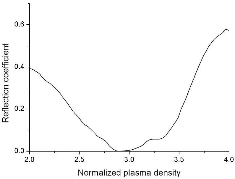
A set of movable 1D gratings with different periods and “duty ratios” have been used in our experiments. When the electric field of the incident wave was directed perpendicular to the grating slits, the reflection reached zero for some distance between the grating and the plasma surface, independently of the value of . An example of the measured dependencies of the reflected signal on the normalized plasma density is shown in figure 3a. This dependence of the reflection coefficient on the normalized plasma density, , can be presented as the dependence of the reflection coefficient on the incident wave frequency, (figure 3b). Indeed, assuming that the angle of incidence is small, , the resonance condition (1) can be presented as follows:
| (3) |
Here is the klystron operating frequency and is the critical plasma density for this frequency. The solution of equation (3) has the form:
| (4) |
where and .
Equation (4) allows presentation of the experimentally measured dependence for the fixed frequency GHz as the dependence of the reflection coefficient on the incident wave frequency, , for a fixed plasma density .
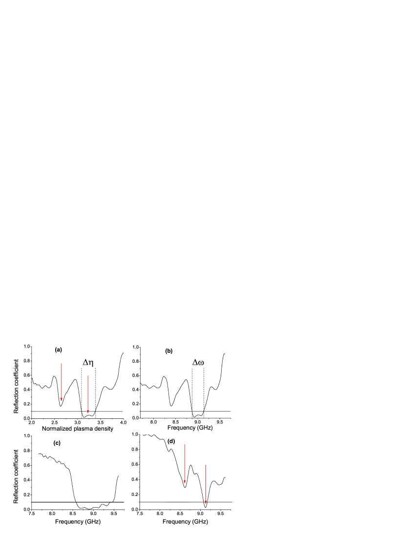
The dependencies presented in Figs. 3b-d for gratings with different duty ratios are characterized by a set of peculiarities which can be explained theoretically in what follows. First, the resonant plasma densities corresponding to the reflection minima were found close to the values and , which follows from equation (2), but did not coincide with them (see figure 3a). The resonant frequencies (resonant plasma densities) depend on the duty ratio whereas this dependence is absent in equation (2). Second, the dependencies have a similar shape for the small () and the large () values of the grating duty ratio . This shape is characterized by two relatively narrow minima (marked by red arrows in figure 3), one of which reaches zero. In contrast, in the grating with the middle-value duty ratio (), the dependence is characterized by a very broad single minimum. The range of frequency (plasma density) variation, which corresponds to the small reflectivity, overlaps the regions of the two minima mentioned above.
The dependencies depicted in figure 3 correspond to the distances between the grating and the plasma surface when the reflection drops to zero. These distances are different for gratings with different duty ratio : . An example of the dependence of the minimal value of the reflection coefficient on the distance for a given grating is shown in figure 4. The existence of a certain distance when the reflected signal reaches zero is the manifestation of the critical coupling effect.

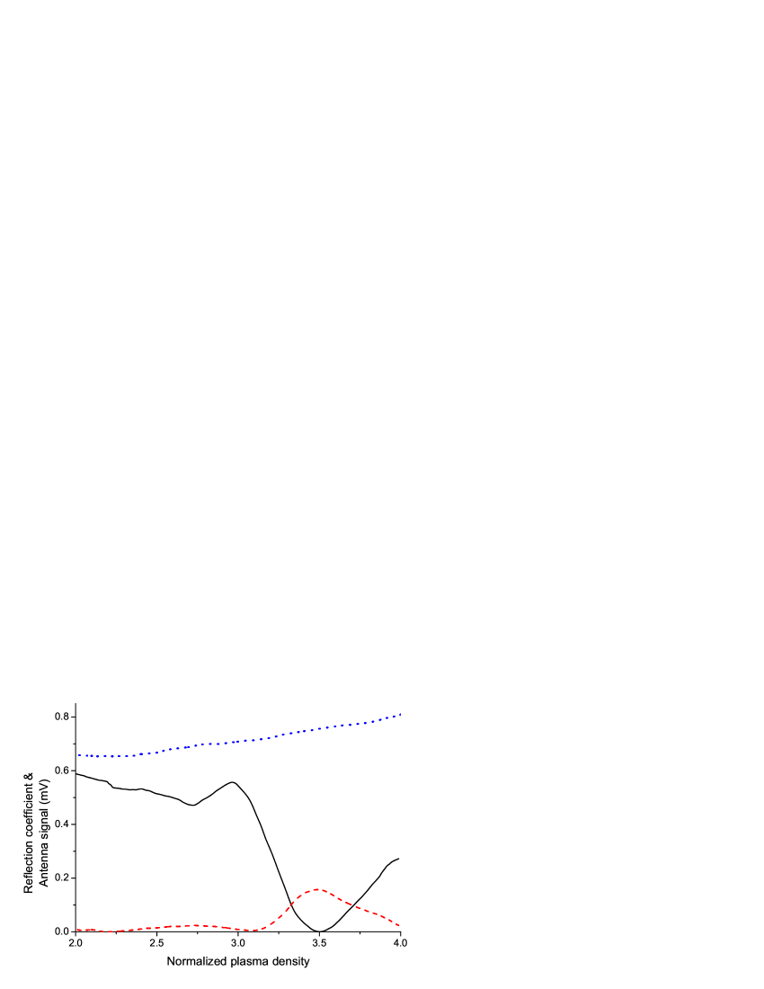
The results described above have been obtained when the distance is small, mm. In this case the SPP excitation is responsible for the incident wave absorption. This is confirmed by the detection by a miniature antenna of a significant rise of the electric field under the plasma surface (see figure 5). The absorption and the antenna signal disappear when the wave electric field is directed along the grating slits and the SPP can not be excited (dotted blue line in figure 5).
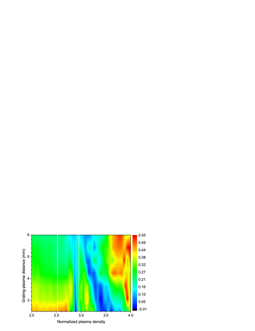
The dependence of the reflection coefficient on the normalized plasma density and the grating-plasma distance is shown in figure 6. The reflection is suppressed in two regions that correspond to excitation of surface plasmon-polaritons propagating in opposite directions. The deviation of the positions of these experimentally determined regions from those calculated using equation (3) (vertical white lines in figure 6) and the dependence of the positions on the distance , which is absent in equation (3), will be discussed in what follows.
III.3 1D grating, large distance
Another region of the reflection coefficient suppression has been found at large distances . A significant decrease of the reflection has been observed for gratings with low duty ratio only. Under the increase of the distance , the reflectivity minimum appears at low plasma density and moves fast to higher density (see figure 7). The incident wave absorption in this region of distances is not connected with the SPP excitation. The absorption is caused by the excitation of the resonator formed between the grating and plasma surface. It was confirmed experimentally when a copper plate was used instead of plasma surface. Results of this experiment are presented in figure 8.
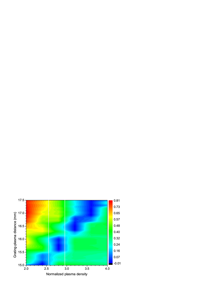

Note that the distance that corresponds to the reflection minimum coincides with in the experiment with the copper plate and is smaller than in the experiments with plasma. This distinction between the two experiments will also be explained theoretically in the next section.
III.4 2D circular grating
The qualitative analysis presented in section II has been successfully confirmed experimentally. In figure 9 the dependence of the reflected signal on the plasma density is shown. The reflection is characterized by a broad minimum and reaches zero at the resonant plasma density. Recalculating the dependence as the dependence , one can see that the reflection coefficient does not exceed 10% in the frequency band GHz, i.e. the relative half-width reaches 4%. This value essentially exceeds the relative half-width % obtained in the Ref. 22 with the use of a doubly periodic grating with square symmetry. This difference can be explained qualitative in the following way.
The circular grating can be conventionally characterized by a radial reciprocal vector whose direction is varied continuously with the angular coordinate . When the angle of incidence differs from zero ( in the experiment), the scattered field is characterized by a continuous set of wave vectors . It is worth to note once more that in this case the reflection coefficient is independent of the wave polarization.
IV Theoretical model
The diffraction grating is semitransparent for propagating waves, therefore the space between the overdense plasma (which reflects propagating waves) and the grating forms a resonator which will be marked below as a resonator-2 whereas SPP will be marked as resonator-1. An eigenfrequency of the resonator-2 is determined by the condition that the wave accumulates the phase by multiples of along the round trip between the grating and the plasma surface. It is necessary to note that reflection from a plasma whose density is large but finite, is accompanied by a non-zero phase shift . As a result, the distance between the grating and the plasma for which the wave frequency coincides with the resonator-2 eigenfrequency depends on the plasma density:
| (5) |
The resonant distance tends to (where is the wavelength) asymptotically when the plasma density tends to infinity, when . This explains why the experimentally measured distance which corresponds to the reflection minima is smaller than and depends on the plasma density as it is shown in figure 7. The dependence in equation (5) of the resonant distance on the plasma density is depicted in figure 10. The density in this figure is varied in the range that corresponds to the experimental conditions.

Resonator-2 also possesses radiative and dissipative Q-factors. The first one is determined by the grating transparency, i.e. by the grating duty ratio , whereas the second one is determined by the dissipation in the plasma skin layer.
When the distance between the grating and the plasma surface coincides with (or the wave frequency coincides with the resonator-2 eigenfrequency) and the critical coupling condition is satisfied, the reflection coefficient vanishes. This mechanism of the wave absorption by the overdense plasma is not connected with the excitation of surface waves.
Thus, there are two separate domains of the system parameters where reflection can be strongly suppressed. They are connected with excitation of either resonator-1 or resonator-2. The critical coupling condition, , can be achieved for resonator-1 by a proper fitting of the distance which determines the radiative Q-factor. In contrast, this can not be done for resonator-2, because the distance determines not the radiative Q-factor but the eigenfrequency of this resonator. The radiative Q-factor of resonator-2 depends on the grating transparency, i.e. on the grating duty factor and the mutual orientation of the wave polarization vector and the grating reciprocal vector .
The above-mentioned peculiarities of the experimental results can be explained using the following simple model of coupled resonators, two resonators-1 (when the angle of incidence is not equal to zero) and one resonator-2. The monochromatic incident wave penetrating through a semitransparent wall (diffraction grating) excites resonator-2. The scattering of the resonator-2 wave field on the grating produces the evanescent waves which excite the SPPs (two resonators-1) at the plasma surface. This process can be modeled by the following equations:
| (6) |
Here are the resonators-1 eigenfrequencies, is the resonator-2 eigenfrequency, are the corresponding resonators dissipation coefficients, is proportional to the incident wave amplitude, and is the coupling coefficient which describes mutual transformation of the propagating and evanescent waves on the grating surface. The functions and represent the resonators-1 and resonator-2 fields, respectively.
The eigenfrequaencies and are defined by the dispersion equations (1) and (5) which should be solved for as a function of the normalized plasma density and the grating-plasma distance . Note, that a real solution of equation (5) exists only when . The coupling coefficient depends on the distance as , where is the evanescent wave spatial decrement. The dissipation coefficient is associated with the plasma electron collision frequency : . The coefficient is defined by the grating transparency, i.e., by the grating duty ratio , and the field leaking through the open lateral surface of resonator-2.
The suppression of the incident wave reflection is associated with an enhanced dissipation rate of the electromagnetic energy in the plasma. This dissipation, in turn, is proportional to the energy density of the electromagnetic field in the plasma skin layer, i.e., it is proportional to the energy density of the fields of all three resonators: . The energy density is maximal near the resonant frequencies of the system which are shifted from their non-perturbed values , , and due to the coupling between the resonators. Thus, the solution of Eqs. (IV) allows determination of the regions in the -plane where the reflection coefficient can be small. The relative distribution of the electromagnetic energy obtained by numerical solution of equation (IV) is shown in figure 11 as a color map. The reflection is suppressed in the red-yellow-colored regions. Solutions of equation (IV) with various values of the parameters , , and showed that the position of the regions where the energy density is large depends mainly on the value of the coupling coefficient , whereas the dissipative coefficients determine the regions width. Some parameters like the operating frequency and the grating period are exactly determined by the experimental conditions, while other parameters can be estimated using the plasma parameters and the geometry of resonator-2 as follows: , .
Let us compare now the experimental results presented in figures 6 and 7 with the theoretical results depicted in figure 11.
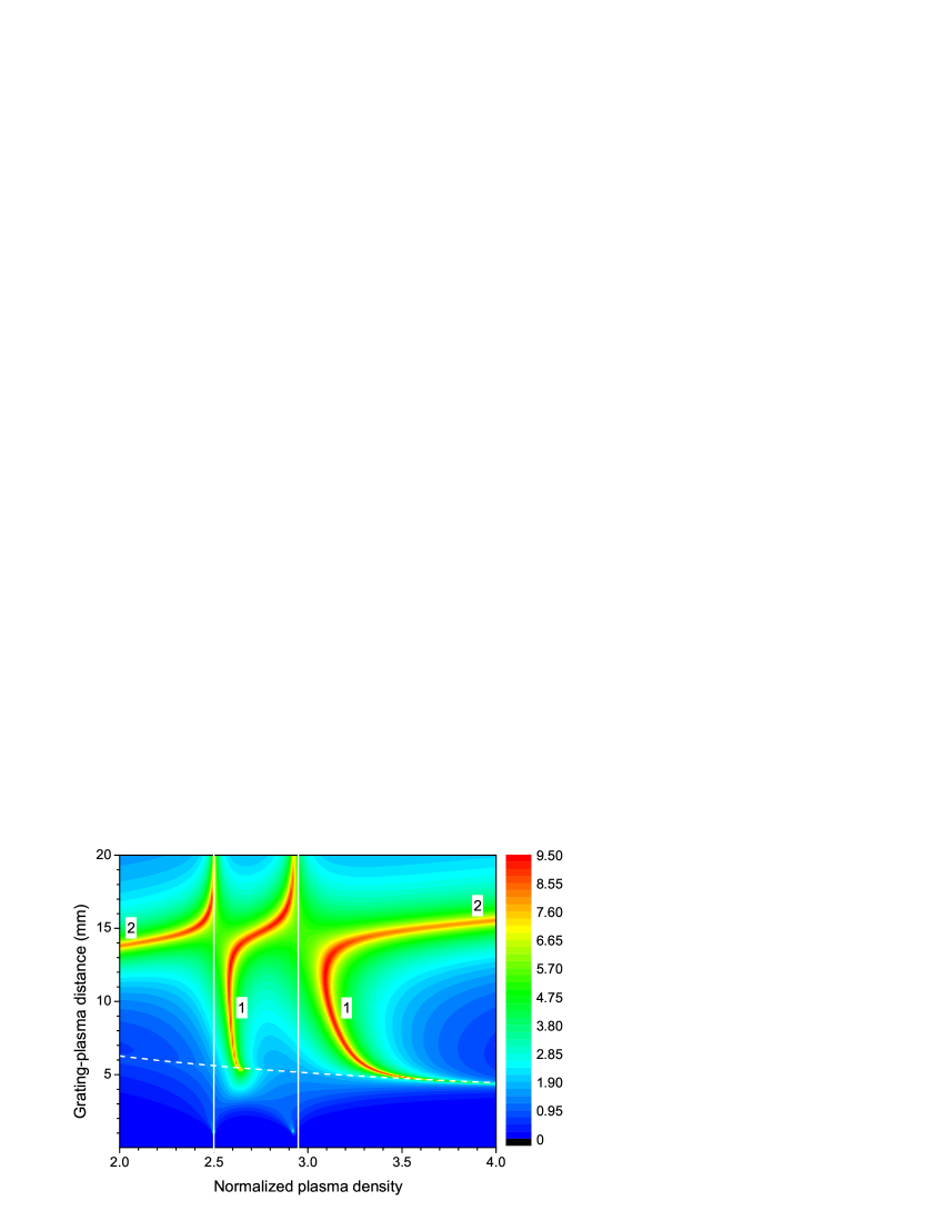
The minima of the reflection coefficient coincide with the maxima of . Figure 11 shows, first, that for small distances when the reflection suppression is associated with the SPP excitation, the plasma density corresponding to the reflection coefficient minima is higher than the resonant plasma densities defined by equation (1). This is in agreement with the experimentally measured dependencies of the reflection coefficient on the plasma density. Second, upon increasing the distance , the difference between the resonant densities defined by equation (1) and the densities corresponding to the reflection minima decreases both in the experiment and in the theory. Third, the dependence of the lower resonant density on the distance is much weaker than it is for the higher resonant density, both in figures 6 and 11.
As regards to the large distances, the experimental as well as the theoretical data demonstrate the same behavior: the resonant distance where the reflection is small, depends weakly on the normalized plasma density and grows when the density increases (compare figure 7 and regions ”2” in figure 11). Moreover, two gaps in the reflection minima which are located in the vicinity of the unperturbed resonant densities (white lines in the figures), are clearly visible in the experimental and the theoretical figures.
Thus, the simple theoretical model of coupled resonators explains qualitatively all the peculiarities of the experimentally measured dependencies.
V Summary
We have shown both experimentally and theoretically that the range of parameters where surface plasmon-polaritons are effectively excited by a freely propagating electromagnetic wave can be essentially broadened due to combination of two factors: a non-zero angle of incidence and a two-dimensional circular diffraction grating. The usage of axially-symmetrical grating makes the SPP excitation entirely independent of the wave polarization. In our experiments we used a wave beam whose transversal cross section coincided with the grating aperture. The 2D superlattice composed of circular gratings used in the experiments is able to utilize completely a wide wave beam for SPP excitation. This statement can be verified in the infrared or visible frequency range with a solid state plasma.
There are two sets of problems where the total absorption of electromagnetic waves is a desired result. The first one is cloaking – making an object invisible in a reflected signal (making invisible for radar, for instance). There is no difference for this purpose where the incident wave energy disappears. For the second set of problems (plasma heating, enhancement of photovoltaic cells efficiency, etc.) the dissipation mechanism plays the key role. Depending on the aim, either localized or propagating surface waves can be used the most effectively. Indeed, localized plasmon-polaritons are eigenmodes of subwavelength resonators (voids Teperik , silver microparticles Pillai ) and dissipation of an incident wave occurs mainly due to the energy loss in these resonators. Part of the wave energy can be used for intensification (due to enhancement of electromagnetic fields in the vicinity of these resonators) of some processes (photoeffect, for instance) in a substrate. In contrast to localized modes, propagating plasmon-polaritons provide spatially homogeneous coupling with the substrate (or even being eigenmodes of the substrate interface, as it occurs with plasma) and the energy dissipation can be caused mainly by processes in the substrate.
Thus, the merits of localized plasmon-polaritons are low sensitivity to the electromagnetic wave angle of incidence and polarization. A disadvantage is their relatively weak and spatially inhomogeneous coupling with a substrate. When the goal is reflectivity suppression only, this disadvantage is of no significance. On the contrary, propagating (delocalized) plasmon-polaritons are sensitive to the wave polarization and angle of incidence, but can be rather strongly coupled with the substrate. The results presented in this paper show how this sensitivity can be essentially suppressed.
References
- (1) R.H. Ritchie, Phys. Rev. 106, 874 (1957).
- (2) R. Zia, J.A. Schuller, A. Chandran, and M.L. Brongersma, Materials Today 9, 20 (2008).
- (3) E. Ozbay, Science 311, 189 (2006).
- (4) T.W. Ebbesen, H.J Lezec, H.F. Ghaemi, T. Thio, and P.A. Wolff, Nature 391, 667 (1998).
- (5) N. Sternberg and A.I. Smolyakov, IEEE Trans. Plasma Sci. 37, 1251 (2009).
- (6) A. Otto, Z. Phys. 216, 398 (1968).
- (7) E. Kretschmann E and H. Raether, Z. Naturforsch. A 23, 2135 (1968).
- (8) V.G. Veselago, Usp. Fiz. Nauk 92, 517 (1967); V.G. Veselago and E.E. Narimanov, Nature Materials 5, 759 (2006).
- (9) J.B. Pendry, Phys. Rev. Lett. 85, 3966 (2000).
- (10) R. Ruppin, Phys. Lett. A 277, 61 (2000 ).
- (11) S. Pillai, K.R. Catchpole, T. Trupke, and M.A. Green, J. Appl. Phys. 101, 093105 (2007).
- (12) T.V. Teperik, F.J. Garcia de Abajo, A.G. Borisov, M. Abdelsalam, P.N. Barlett, Y. Sugawara, and J.J. Baumberg, Nature Photonics 2, 299 (2008).
- (13) Y.P. Bliokh, Opt. Commun. 259, 436 (2006).
- (14) Y.P. Bliokh, J. Felsteiner, and Y.Z. Slutsker Phys. Rev. Lett. 95, 165003 (2005).
- (15) C.S. Liu, V.K. Tripathi, and R. Annou, Phys. Plasmas 15, 062103 (2008).
- (16) Y. Wang, J.-X. Cao, G. Wang, L. Wang, Y. Zhu, and T.-Y. Niu, Phys. Plasmas 13, 073301 (2006).
- (17) Z. Chen, M. Liu, L. Tang, J. Lv, W. Yuanfang, and X. Hu, J. Appl. Phys. 106, 063304 (2009); Z. Chen, M. Liu, L. Tang, P. Hu, and X. Hu, J. Appl. Phys. 106, 013314 (2009).
- (18) L. Lin, R.J. Reeves, and R.J. Blaikie Phys. Rev. B 74, 155407 (2006).
- (19) K.Y. Bliokh, Y.P. Bliokh, V. Freilikher, S. Savel’ev, and F. Nori, Rev. Mod. Phys. 80, 1201 (2008).
- (20) J.C. Slater, Microwave Electronics (Princeton: Van Nostrand, 1950).
- (21) R. Adler, L.J. Chu, and R.M. Fano, Electromagnetic Energy Transmission and Radiation (New York: Wiley and Sons, 1960).
- (22) A. Alù and N. Engheta, J. Opt. A, Pure Appl. Opt. 10, 093002 (2008).
- (23) P. Alitalo and S. Tretyakov, Materials Today 12, 22 (2009).
- (24) Yu.A. Akimov, K. Ostrikov, and E.P. Li, Plasmonics 4, 107 (2009).
- (25) E. Popov, D. Maystre, R.C. McPhedran, M. Nevière, M.C. Hutley, and G.H. Derrick, Opt. Express 16, 6146 (2008).
- (26) T. Matsui, A. Agraval, A. Nahata, and Z.V. Vardeny, Nature 446, 517 (2007).
- (27) Y.P. Bliokh, J. Felsteiner, Ya.Z. Slutsker, and P.M. Vaisberg, Appl. Phys. Lett. 85, 1484 (2004); Y.P. Bliokh, Yu.L. Brodsky, Kh.B. Chashka, J. Felsteiner, and Ya.Z. Slutsker, J. Appl. Phys. 103, 053303 (2008); Y.P. Bliokh, Yu.L. Brodsky, Kh.B. Chashka, J. Felsteiner, and Ya.Z. Slutsker, Plasma Sources Sci. Technol. 18, 015009 (2009); Y.P. Bliokh, Yu.L. Brodsky, Kh.B. Chashka, J. Felsteiner, and Ya.Z. Slutsker, J. Appl. Phys. 107, 013302 (2010).