∎
Greenbelt, Md 20071 USA
Tel.: (301)286-6546
22email: gehrels@milkyway.gsfc.nasa.gov 33institutetext: J. K. Cannizzo 44institutetext: CRESST/UMBC/NASA/GSFC/ASD/Code 661
Greenbelt, Md 20071 USA
Gamma-Ray Telescopes
Abstract
The last half-century has seen dramatic developments in ray telescopes, from their initial conception and development through to their blossoming into full maturity as a potent research tool in astronomy. Gamma-ray telescopes are leading research in diverse areas such as ray bursts, blazars, Galactic transients, and the Galactic distribution of 26Al.
Keywords:
Gamma rays: general - telescopes - bursts - blazars - Galactic transients1 Introduction
The current panoply of high-energy astronomical observatories is impressive: INTEGRAL, Swift, Fermi-GLAST, RHESSI, Suzaku, and AGILE. These satellites have made fundamental contributions to their fields and in fact have had broad impact beyond their immediate purviews. These areas of study include ray bursts (Swift, INTEGRAL, Fermi-GLAST), solar physics (RHESSI), supernovae (Swift), Galactic astronomy (INTEGRAL, Fermi-GLAST), Galactic transients (Swift, Suzaku), and AGN (Suzaku).
2 Background
A basic consideration of the theory of photon interaction as a function of energy divides naturally into three regimes: photoelectric interactions at MeV, Compton scattering for MeV, and pair production for MeV (Figure 1).
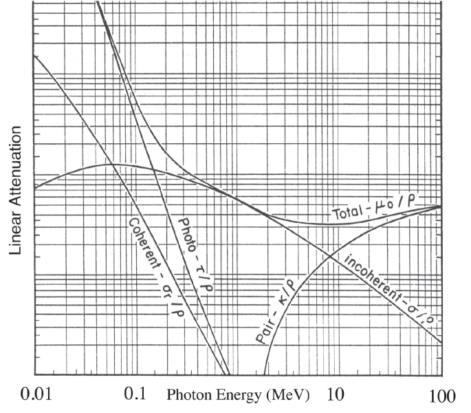
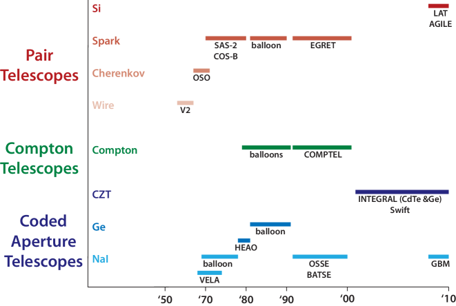
This natural ordering has provided the impetus for three basic telescope designs, (i) coded aperture mask for low energies, in which the illumination of a non-redundant array grid casts a shadow on a detector, thereby giving a sky position (e.g., the BAT on Swift), (ii) a Compton telescope for medium energies (e.g., COMPTEL on CGRO, and (iii) pair telescope in which an incident high-energy ray interacts with a medium and produces a pair. The secondary phase consists of signal detection, which for the three cases is carried out by (i) scintillators (e.g., NaI, BGO, CsI, LaBr3, and GSO), (ii) solid state detectors (e.g., Si, CdZnTe, Ge, HgI2), and (iii) pair trackers (e.g., spark chamber, Si). Figure 2 shows the history of ray technology, with examples of observatories based on these 3 strategies.
3 Telescope Technologies
3.1 Low Energy Gamma Ray Telescopes
The earliest astronomical spacecraft (actually - unintentionally astronomical) to utilize collimated detectors were the Vela satellites (Klebesadel, Strong, & Olson 1973). Each carried six 10 cm3 CsI scintillation counters distributed so as to achieve optimal nearly isotropic sensitivity. The detectors were sensitive in the energy range between and MeV for Vela 5 and MeV for Vela 6, with a detector efficiency . The scintillators were shielded against direct penetration by electrons below MeV and protons below MeV. A high shield (i.e., a shield to protect against nuclei with large atomic number) attenuated photons with energies below that of the counting threshold. No active anti-coincidence 111In anticoincidence counting, two counters are connected so that a pulse is recorded by one of them only if there is no simultaneous pulse in the other. This is useful in rejecting particles that do not originate from the source being studied. shielding was provided. The accumulated data included a background component due to cosmic particles and their secondary effects. The observed background rate was c s-1 for Vela 5 and c s-1 for Vela 6.
HEAO-I (1977-1979) had gas-proportional counters, with each counter possessing a multigrid collimator (Wood et al 1984). Each collimator was composed of a stack of etched Mo sheets interleaved with spacer frames. To maintain thermal stability a heat shield made of 2 m Kimfol polycarbonate film and coated with 80 nm of Al was put in front of each collimator. Incident X-rays passed through the heat shield and Mylar film, with the net transmission of the two layers determining the response to soft X-rays.
Collimation of rays and background reduction for the OSSE instrument (Johnson et al. 1993) aboard CGRO (1991-2000) were achieved via active shielding and a passive W collimator. Each of the four OSSE detectors consisted of a NaI scintillation crystal shielded behind by an optically coupled 7.6 cm thick CsI scintillation crystal in a “phoswich” (phosphor sandwich) configuration. Each phoswich was enclosed in an annular shield of NaI scintillation crystals providing anticoincidence for ray interactions in the phoswich. The annular shield also enclosed a W slat collimator which sets the FWHM ray FOV of the phoswich detector.
The BAT instrument on Swift (2004-) has a D-shaped coded mask222 The concept of the coded mask was discovered by Aristotle. As he was walking under some trees, he noticed that patches of sunlight on the ground were in the shape of the Sun and not of the gap between the branches. The trees acted in the same way as a coded mask. made of Pb tiles ( mm) mounted on a 5 cm thick composite honeycomb panel which is mounted by composite fiber struts 1 m above the detector plane (Gehrels et al. 2004). The BAT coded mask uses a random 50% open/50% closed pattern rather than the more common uniformly redundant array pattern. The mask area is 2.7 m2, which yields a half-coded FOV of 1.4 sr.
3.2 Pair Telescopes
OSO-3 (1967-1968) achieved the first extensive ray observation in space, using a Cerenkov scintillator detector (Badhwar, Kaplon, & Valentine 1974), and showed the Galactic disk to be a strong source of high-energy rays. The detector consisted of 0.64 cm thick plastic scintillators and a 1 in thick lucite Cerenkov radiator over a 0.16 cm thick Pb sheet to convert rays into pairs. The discriminator thresholds on all detectors were set using sea level muons. The energy threshold was 50 MeV (1%), rising to 13.5% at 200 MeV, and 17% at 1 GeV, where the percentages indicate the fraction of the total geometric area. The false alarm rate for singly charged particles was about 0.15%.
The ray telescope flown on SAS-2 (1972-1973) consisted of an assembly with 16 spark chamber modules above a set of four plastic scintillators, with another 16 modules below the scintillators (Fichtel, Kniffen, & Hartman 1973). Thin W plates (which had a thickness of radiation lengths) were interleaved between the spark chamber modules, with an area cm2. The large number of W plates and spark chambers provided material for an incoming ray to be converted into a pair, which could then be identified and used to provide a direction for the incoming ray, and a way of determining the energy of the electrons in the pair by measuring the Coulomb scattering. The sensitivity range of the instrument was about MeV.
After Vela, COS-B (1975-1982) was the primary workhorse for studying ray bursts (Boella et al. 1976). COS-B consisted of a dome-shaped 1.1mmm thick plastic scintillator viewed by nine photomultipliers for rejection of charged particles (the anti-coincidence counter, or ACO). The ACO maximum sensitivity was at 700 KeV.
The EGRET instrument (Kanbach et al. 1988) on CGRO consisted of an anticoincidence system, a spark chamber with interspersed conversion material to materialize the incident photons and determine the trajectory of the secondary pair, a triggering device to detect the presence of charged particles with the correct direction, and an energy measuring device - a total-absorption spectrometer NaI crystal. The 2-cm-thick plastic scintillators were viewed by 24 photomultiplier tubes coupled to the lower perimeter so as to keep the EGRET FOV free of irregular mass distributions. The conversion of the incoming rays into pairs occurred in an upper stack of 28 spark chambers interleaved with Ta foils with an average thickness of 90 m ( radiation lengths). The total depth for on-axis radiation was hence about 0.54 radiation lengths, leading to a conversion efficiency of about 30% at 100 MeV. The volume of the upper chamber was cm3, so that an effective area cm2 resulted for the center of the FOV.
The LAT (Atwood et al. 2009) on board Fermi-GLAST (2008-) is a pair conversion telescope with a precision converter-tracker and calorimeter, each consisting of a array of 16 modules supported by a low-mass Al grid structure. A segmented anticoincidence detector covers the tracker array, and a programmable trigger and data acquisition system uses prompt signals from the tracker, calorimeter, and anticoincidence detector subsystems to form a trigger. The precision converter-tracker has 16 planes of high-Z material in which rays incident on the LAT can convert to an pair. The converter planes are interleaved with position-sensitive detectors that record the passage of charged particles, thus measuring the tracks resulting from pair conversion. This information is used to reconstruct the directions of the incident rays, Each tracker module has 18 , tracking planes, consisting of two layers ( and ) of single-sided Si strip detectors. The 16 planes at the top of the tracker are interleaved with high-Z convert material (W), i.e., material capable of generating interactions with nuclei of high atomic number.
3.3 Compton Telescopes
The COMPTEL instrument (Schönfelder 1991) on CGRO combined a large FOV with imaging. It consisted of two detector arrays, and upper one of low-Z material and a lower one of high-Z material. In the upper detector an incoming ray was Compton scattered, and the scattered photon subsequently made a second interaction in the lower detector. A time-of-flight measurement was utilized to confirm the causal relation. The locations and energy losses of both interactions were monitored. For events that were completely absorbed, the arrival direction of the ray had to lie within a known angle of the direction of the scattered ray, which allowed a determination of its original direction on the sky. Incompletely absorbed events yielded uncertainty cones that did not constrain the source position.
3.4 Focusing Telescopes
Actual imaging of hard X-rays ( keV) can be achieved using multilayer mirrors. The technology has been proven with the InFOCS balloon instrument, which obtained a 2.6 arcmin resolution image of 4U 0115 (Tueller et al 2005). The Pt/C reflector surface multilayer mirror had a diameter of 40 cm and a focal length of 8 m. The incident angle could lie in the range deg. There were 255 nestings and 2040 reflectors. The overall telescope had an effective area of 49 cm2 at 30 keV, an angular resolution of 2.4 arcmin (half-power diameter), and a field of view of 11 arcmin.
Currently under development is the NuSTAR instrument, a NASA SMEX mission slated for launch in which will contain an extensible boom for its multilayer mirrors, and CdZnTe detectors (Harrison et al. 2005). HEFT, a proof-of-concept balloon payload, contains three co-aligned conical-approximation Wolter I mirrors, each of which focuses hard X-rays/soft rays onto a shielded solid-state CsZnTe focal plane. Each of the three optics has 70 shells, with radii between 4 and 12 cm. The reflectors are coated with W/Si multilayers, providing good reflectance up to the W K-edge at 69.5 keV. The total collecting area on-axis at 30 keV is 100 cm2. NuSTAR consists of three co-aligned telescope modules with a 10-m focal length, and the optics and detectors are placed at either end of an extensible mast. The optics consist of 130 shells each, with radii between 5.5 and 16.9 cm. The shells are coated with a combination of W/SiC and Pt/SiC multilayers. Combined with low graze angles, the smooth response goes up to 80 keV. NuSTAR will achieve angular resolution of 40 arcsec (half-power diameter). The NuSTAR and HEFT focal plane detectors have the same dimensions, but the NuSTAR detectors are surrounded by an active CsI shield rather than graded-Z/plastic shield.
Looking further into the future, new methods are being discussed that could in principle take advantage of the very short wavelength of rays to achieve ultra-high resolution imaging. The diffraction-limited angular resolution
| (1) |
where is the lens diameter. This ultra-high resolution could be applied to directly image the event horizons of black holes. One technique for accomplishing direct, high-resolution imaging is through Fresnel lenses (Skinner et al. 2004). Fresnel zone plates (FZPs) focus radiation by blocking with opaque annuli the photons contributing to spatial frequencies that would arrive at the image plane non-optimally. This technique is similar in spirit to “apodization” (literally - “reducing the feet” - referring to the diffraction pattern) used by optical astronomers in which a PSF is enhanced by minimizing the higher order maxima of the diffraction pattern, effectively by throwing more of the light into the central, on-axis maximum. Phase Zone Plates (PZPs) go one step better by replacing the opaque annuli with media possessing a thickness of refractive material which imposes a phase shift of . The final step in improvement consists of Phase Fresnel Lenses (PFLs) in which the refractive material has a profile that is radial with respect to the central optical axis, so that all the radiation arrives at the focal point with exactly the correct phase. This is an exact analog of the optical astronomers’ apodization. The use of PFLs for high-energy photons is achievable because all materials have a refractive index that differs from unity. For X-rays and rays the refractive index , where is a small positive number, leading to a value slightly less than unity.
Another possibility for direct imaging is through the use of Laue concentrators (von Ballmoos et al. 2004). This method takes advantage of the phase information carried within the high-energy photons by using Bragg diffraction, which refers to the interference between the periodic (wave) nature of light and the periodic structure of matter in a crystal lattice. In a Laue diffraction lens, a large number of crystals are oriented in an annular configuration so that incident photons are imaged onto a common focal spot. The background noise is kept low because of the resultant small detector volume. In a Laue-type crystal diffraction lens the crystals are positioned along concentric rings. In order to be diffracted the wavelength and incident angle of the incoming photon must obey the Bragg relation
| (2) |
where is the crystal plane spacing, the incident angle of the photon, the reflection order, and the photon wavelength. A crystal at a distance from the optical axis is oriented such that the angle between the incident beam and the crystalline planes is the Bragg angle . For a given focal distance of the lens, the radius of the th ring is given by
| (3) |
where is the crystalline plane spacing of the th ring. The bandwidth
| (4) |
where is the angular range over which the crystals reflect monochromatic radiation, and Ge[111] refers to the germanium crystalline plane.
4 History
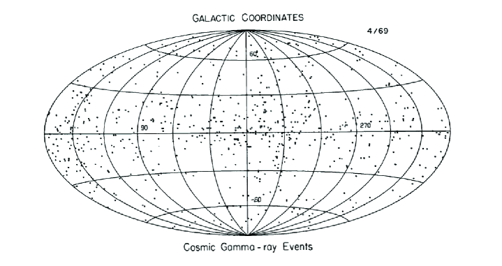
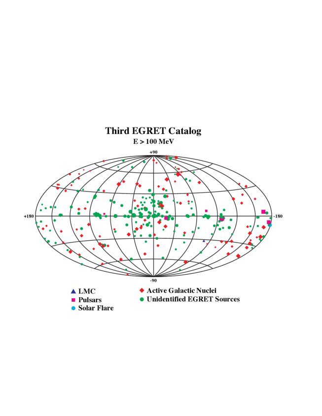
The first ray detector was launched on a V2 rocket as a suborbital flight. It was sensitive in the range MeV and used wire ionization detectors. The astrophysical findings were upper limits (Perlow & Kissinger 1951ab). The first ray maps were made by Explorer-11 and OSO-3. The high-energy instruments on these satellites were of the cathode-ray type, and their design foreshadowed future directions in their use of converter, calorimeter, and plastic anticoincidence (Kraushaar, Clark, & Garmire 1968). Figure 3 shows the first ray map, a distribution characterized by a broad maximum toward the Galactic center, and an isotropic component with a softer energy spectrum. The spark-chamber era, spanning 20 MeV 10 GeV, was dominated by COS-B from 1975 to 1981, and by EGRET on CGRO from 1991 to 2000. The current instrument continuing this thread is the LAT on Fermi-GLAST, with channels and 70 m2 of Si surface. The Galactic map obtained by EGRET has yielded a plethora of Galactic sources and enriched our knowledge of their high-energy behavior. The third EGRET catalog (Figure 4), which contains data from 1991 April 22 to 1995 October 3, has 271 sources ( MeV). The list includes a solar flare, the LMC, five pulsars, one probable radio galaxy detection (Cen A), 66 blazars, and 170 unidentified EGRET sources (Hartman et al. 1999). Model predictions indicate that Fermi-LAT should be able to detect 9900 sources at in a one-year all-sky survey.
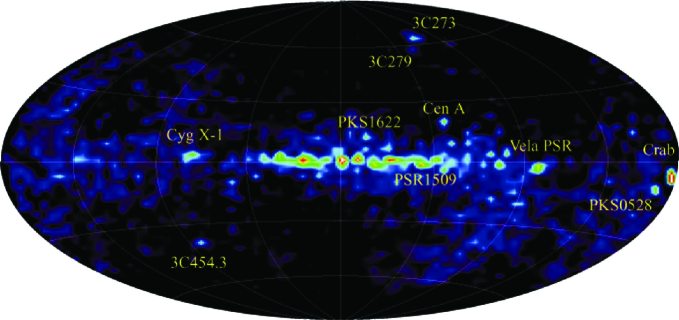
Early Compton telescopes ( MeV) were flown on balloon programs at MPE in Germany, and UC Riverside and UNH in the US. This unexplored energy range is technically challenging due to scattering, and localizations on the sky are typically to . A major advance was the COMPTEL instrument on CGRO which operated from 1991 to 2000 (Schönfelder et al. 1993). A new window to astronomy was hereby opened: COMPTEL produced a reliable MeV sky map, shown in Figure 5. (Schönfelder et al. 2000). This was the first complete MeV all-sky survey, which found 32 non-variable sources and 31 ray bursters. Among the continuum sources were pulsars that had spun down, stellar black-hole candidates, supernova remnants, interstellar clouds, AGN, ray bursters, and the Sun during solar flares. Line detections were also made: 1.809 MeV (26Al), 1.157 MeV (44Ti), 0.847 and 1.238 MeV (56Co), 2.223 MeV (neutron capture).
The history of GRB research has been almost entirely written by high-energy, space-borne instruments. GRBs were discovered as a phenomenon in 1967 by the Vela satellites (Klebesadel, Strong, & Olson 1973), which were initially launched to verify the atmospheric nuclear test ban treaty. For many years GRB research was strongly impeded by the fact that the distances to the sources were completely unknown. This began to change with the launch of CGRO in 1991 and the use of BATSE and OSSE (Kurfess et al. 1992, 1997). Within a few months, the uniform sky distribution of GRBs made it clear that there was no concentration of sources to the Galactic plane, and therefore GRBs had to lie at either much smaller (solar system), or much larger (cosmological) distances. The tradition of outstanding GRB research begun by BATSE has been continued with the BAT on Swift, which is yielding arcmin localizations using a shadow mask design with CdZnTe detectors (Barthelmy et al. 2005). One of Swift’s major successes has been the first position determination of a short GRB (Gehrels et al. 2005).
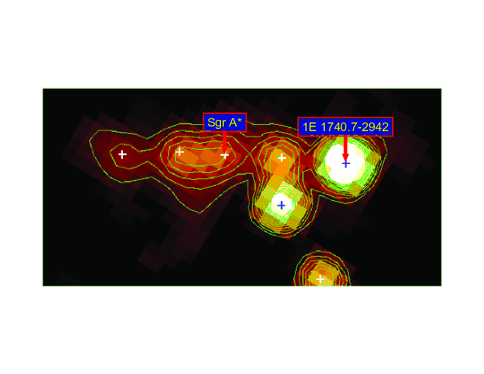
The INTEGRAL sky as seen by the IBIS instrument has built upon the previous COMPTEL results. An all-sky map was produced which represented the first complete scan of the entire central equatorial zone of the Galactic plane at energies above 20 keV with a limiting sensitivity of mCrab. in the central radian (Bird et al. 2006). The resultant catalog also included a substantial coverage of extragalactic fields, and contained more than 200 high-energy sources. The mean position error for sources detected with significance above was arcsec, enough to identify most of them with a known X-ray counterpart (Bird et al. 2006). This is important given the high Galactic aborption inherent in most earlier surveys. Lebrun et al. (2004) found that the keV Galactic emission is resolved into compact sources. High resolution imaging ( arcmin) of the Galactic center at high energies is a very recent development in the field of high-energy astrophysics. Bélanger et al. (2006) studied the persistent high-energy flux from the Galactic center using the the IBIS/ISGRI imager on INTEGRAL (Figure 6). For the first time they detected a hard X-ray source, IGR J17456-2901, located within arcmin of Sagittarius A* (Sgr A*) in the energy range keV. By combining the ISGRI spectrum with an X-ray spectrum corresponding to the same physical region around Sgr A* from XMM-Newton taken during part of the INTEGRAL observations, they inferred a keV luminosity at 8 kpc of erg s-1. They also set a upper limit on the flux at the electron-positron () annihilation energy of 511 keV from the direction of Sgr A* at photons cm-2 s-1.
5 Conclusion
Gamma-ray astronomy has taken enormous strides in the last few decades. Dramatic improvements in both spectral and imaging capabilities have thrust ray telescopes into the forefront of astronomical research. For about a decade the prompt localizations so essential to GRB research were carried out largely by CGRO; now the torch has been passed to Swift. The Galactic center has now been explored in a new and interesting way, via rays, and our knowledge of transient sources in the Galactic bulge and the diffuse Galactic background has deepened. Future missions that seek to take advantage of the ultra-high resolution potential of ray observing at the diffraction limit offer the hope of direct imaging of nearby black hole event horizons - which would allow us to probe directly General Relativity in the strong field limit.
References
- (1) Atwood, W. B. et al.: ApJ 697, 1071 (2009)
- (2) Badhwar, G. D., Kaplon, M. F., & Valentine, D. A.: Astrophys. Space Sci. 27, 147 (1974)
- (3) Barthelmy, S. D., et al.: Space Sci. Rev. 120, 143 (2005)
- (4) Bélanger, G., Goldwurm, A., Renaud, M., Terrier, R., Melia, F., Lund, N., Paul, J., Skinner, G., & Yusef-Zadeh, F.: ApJ 636, 275 (2006)
- (5) Bird, A. J., et al.: ApJ 636, 765 (2006)
- (6) Boella, G., Gorisse, M., Paul, J., Taylor, B. G., & Wills, R. D.: Astrophys. Space Sci. 42, 103 (1976)
- (7) Fichtel, C. E., Kniffen, D. A., & Hartman, R. C.: ApJ 186, L99 (1973)
- (8) Gehrels, N., et al.: ApJ 611, 1005 (2004)
- (9) Gehrels, N., et al.: Nature 437, 851 (2005)
- (10) Harrison, F. A., et al.: Exp. Astron. 20, 131 (2005)
- (11) Hartman, R. C., et al. ApJS 123, 79 (1999)
- (12) Johnson, W. N., Kinzer, R. L., Kurfess, J. D., Strickman, M. S., Purcell, W. R., Grabelsky, D. A., Ulmer, M. P., Hillis, D. A., Jung, G. V., Cameron, R. A.: ApJS 86, 693 (1993)
- (13) Kanbach, G., et al.: Space Sci. Rev. 49, 69 (1988)
- (14) Klebesadel, R. W., Strong, I. B. & Olson, R. A.: ApJL 182, 85 (1973)
- (15) Kraushaar, W. L., Clark, G. W., & Garmire, G.: Can. J. Phys. 46, 414 (1968)
- (16) Kurfess, J. D., et al.: ApJL 399, 137 (1992)
- (17) Kurfess, J. D., Bertsch, D. L., Fishman, G. J., & Schönfelder, V.: AIPC. 410, 509 (1997)
- (18) Lebrun, F., et al.: Nature 428, 293 (2004)
- (19) Perlow, G. J., & Kissinger, C. W.: Phys. Rev. 81, 552 (1951)
- (20) Perlow, G. J., & Kissinger, C. W.: Phys. Rev. 84, 572 (1951)
- (21) Schönfelder, V.: Adv. Space Res. 11, 313 (1991)
- (22) Schönfelder, V., et al.: ApJS 86, 657 (1993)
- (23) Schönfelder, V., et al.: A A 143, 145 (2000)
- (24) Skinner, G. K., von Ballmoos, P., Gehrels, N., & Krizmanic, J.: SPIE J. 5168, 459 (2004)
- (25) Tueller, J., et al.: Exp. Astron. 20, 121 (2005)
- (26) von Ballmoos, P., et al.: New Astron. Rev. 48, 243 (2004)
- (27) Wood, K. S., Meekins, J. F., Yentis, D. J., Smathers, H. W., McNutt, D. P., Bleach, R. D., Byram, E. T., Chubb, T. A., & Friedman, H.: ApJS 56, 507 (1984)