Positive current noise cross-correlations in capacitively coupled double quantum dots with ferromagnetic leads
Abstract
We examine cross-correlations (CCs) in the tunneling currents through two parallel interacting quantum dots coupled to four independent ferromagnetic electrodes. We find that when either one of the two circuits is in the parallel configuration with sufficiently strong polarization strength, a new mechanism of dynamical spin blockade, i.e., a spin-dependent bunching of tunneling events, governs transport through the system together with the inter-dot Coulomb interaction, leading to a sign-reversal of the zero-frequency current CC in the dynamical channel blockade regime, and to enhancement of positive current CC in the dynamical channel anti-blockade regimes, in contrast to the corresponding results for the case of paramagnetic leads.
pacs:
72.70.+m, 73.23.Hk, 73.63.-b, 72.25.RbQuantum noise cross-correlation (CC) in multiterminal mesoscopic devices far from equilibrium has recently become an active issue because it characterizes the degree of correlation and the statistics of the charge carriers.Blanter ; Nazarov It is believed that in a noninteracting system, the current CC between different normal-metallic leads is always negative due to the fermionic statistics of electrons;Buttiker this has been confirmed experimentally in a Hanbury Brown-Twiss setup.HBT On the other hand, much theoretical work has predicted that current CC may become positive in the following situations: for a hybrid superconductor-normal system;Anantram for a system with three-terminal ferromagnetic leads;Cottet also for a system in the Coulomb-interaction mediated regime;Martin and as a result of feedback effects of external voltage fluctuations.Wu
Very recently, Coulomb-interaction-induced positive current CC was experimentally observed in a double quantum dot (QD) system, with two parallel QDs coupled via an inter-dot Coulomb interaction, and also coupled to four independent electrodes and two independent gates, as shown in Fig. 1.McClure It was found that when the system is biased on the specific occupation parameters, (1,0) and (0,1) [ denotes the electron numbers in the top and bottom QDs], by means of tuning two gate voltages, the electrons occupying one dot during sequential tunneling through that QD can enhance either the tunneling-in rate or the tunneling-out rate of the other dot due to the Coulomb interaction (dynamical Coulomb anti-blockade), resulting in the appearance of a positive CC between the currents through the two QDs (i.e. electron bunching).McClure ; Haupt However, the current CC still remains negative in the transport regimes, (0,0) and (1,1), due to the dynamical Coulomb blockade effect (electron anti-bunching).
In this Letter, we analyze the current CC for the same structure as the one studied in Refs. McClure, ; Haupt, , but with ferromagnetic leads. Experiments with a strongly interacting QD and ferromagnetic contacts have recently been performed successfully,fif and it is not difficult to make such a structure with parallel-coupled QDs connected to four independent ferromagnetic leads, as shown in Fig. 1. Our main finding is that sufficiently polarized contacts can lead to positive current CC even in the Coulomb blockaded region (0,0) if only one of the two circuits is in the parallel configuration. Similar to results for the three-terminal QD with ferromagnetic electrodes studied by Cottet et al,Cottet the present result also stems from dynamical spin blockade, associated with dynamical channel blockade. Furthermore, we find that the sign of current CC reduces to the result for paramagnetic electrodes with increasing spin relaxation rate.
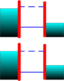
The system we study here consists of two parallel single-level QDs [top and bottom ()] with energies and inter-dot Coulomb interaction , which are coupled to four collinearly spin-polarized leads with net spin-independent tunneling rates and polarization strengths () (Fig. 1). Accordingly, the ferromagnetism of the leads in the top/bottom circuit can be accounted for by the spin-dependent tunneling rates: and for the parallel (P) configuration; and for the anti-parallel (AP) configuration. Moreover, a constant spin-flip scattering rate, , is introduced to model spin relaxation. We also assume infinite on-site Coulomb repulsion to guarantee no double occupation on each dot. Therefore, there is a total of states in this system: no electron in the two QDs, , the top QD occupied by one electron with spin , , the bottom QD occupied by one electron with spin , , and either QD occupied by one electron with spin (), . In the sequential-tunneling limit, electronic transport through such double QDs can be described by the rate equation:Cottet ; McClure ; Dong
| (1) |
in which is the occupation probability for the state . The term gives the total loss rate for the state , while the term () gives the total rate for transitions between the two states and . All these terms depend on the spin-flip transition rate and the spin-dependent rates for tunneling-in and tunneling-out between a QD and its lead () when the other QD is either empty or occupied, and , where is the Fermi function of lead with chemical potential and temperature , and . For example, the total loss rates for the states and are and , respectively. Here, a symmetric bias voltage is assumed to be applied between the left and right leads: .
The steady-state value of under finite bias voltage is obtained by solving in Eq. (1). Then the spin-dependent currents flowing through the right leads can be evaluated as (we use )
| (3) | |||||
| (5) | |||||
and and are obtained by interchanging in Eqs. (3) and (5), respectively. Using the techniques developed in Refs. Cottet, ; McClure, ; noise, ; Djuric, , we introduce spin-resolved current matrices for the two circuits according to Eqs. (3) and (5), and then apply them to the steady-state solutions of Eq. (1) to calculate the average currents and the spin-dependent noise CC defined as
| (6) |
with . The total zero-frequency current CC is .
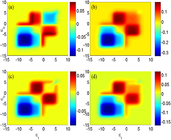
In the following calculation, we focus on the situation of two identical circuits, and . The other parameters are: , and a given bias voltage (hereafter, in the text and in the figures we use as the energy unit). Figure 2 exhibits the calculated zero-frequency current CC dependence on the energy levels of the two QDs, and , for paramagnetic leads (a), and for ferromagnetic leads with strong polarization, , and no spin-flip scattering (b-c). In the paramagnetic case, the current CC is, as expected, negative for the occupation regimes, (0,0) and (1,1), while it is positive for the regimes, (1,0) and (0,1). It is already known that this positive CC stems from interaction-induced enhancement of the tunneling rate.McClure To reveal this with greater clarity, we have derived an analytic expression for the current CC for the regime (1,0) (for example, setting and ) by assuming an enhanced tunneling-in rate for the bottom QD under the condition that the top QD is occupied by an electron, () [correspondingly, the tunneling-out rate is ; the other rates are either or ]. In the limit of zero temperature, the analytic result is given by
| (7) |
Surprisingly, we find that the sign of current CC for the transport regime (0,0) is changed in the presence of ferromagnetic electrodes [Fig. 2(b-c)], and its largest values are obtained in the case when both two circuits are in the P configuration (P-P configuration). Furthermore, the positive CC noise for the transport regimes, (1,0) and (0,1), is enhanced in comparison with those in the case of paramagnetic leads, if either of the two circuits is in the P configuration. This sign-reversal and the enhancement can be explained in terms of the associated effect of dynamical channel blockade and a mechanism of dynamical spin blockade, as suggested by Cottet et al..Cottet
Let us focus on the P-P configuration. Here, we assume that up spins are in the majority. Correspondingly, the dwell time of down spins on the dot is longer than that of up spins since the down spin tunneling rates (slow electrons) are much lower than those of up spins (fast electrons). Considering further the fact that the total number of electrons with up spin, , is equal to that of electrons with down spin, , in this configuration, we can infer that every tunneling event of a down-spin electron flowing through a QD must follow several consecutive tunneling events of up-spin electrons flowing through the QD, i.e. up spins bunching on both circuits. This indicates that for most time intervals, the sign of is the same as that of , but is opposite to that of , which is responsible for the occurrence of positive CC between up spins, (0); but negative CC involves down spins, , for the transport regimes, (0,0), (1,0), and (0,1). We have obtained analytical expressions for the various spin-resolved CCs as:
| (8) | |||||
| (9) | |||||
| (10) |
and for the total CC as:
| (12) |
in the transport regime (0,0) at zero temperature. Clearly, the positive sign of stems from the up-up CC for sufficiently strong polarization in absence of spin-flip scattering (note that the other spin-resolved CCs are all negative). Moreover, retaining spin coherence during tunneling is a necessary condition for such bunching of up spins. We exhibit the effect of spin-flip scattering on the zero-frequency current CCs in Fig. 3. It should be noted that spin-flip scattering strongly influences the up-up CC once is comparable to the tunneling rate ; and in the limit of infinitely high , the CCs tend to the corresponding values of the paramagnetic case for any value of the polarization and any configuration [see Eq. (12)]. In particular, becomes negative around in Fig. 3(a). Moreover, a weak polarization, , can not cause sufficiently strong up-up spin bunching to overcome the negative CCs, and , leading to a small negative value of , as shown in Fig. 3(d) for the results with .
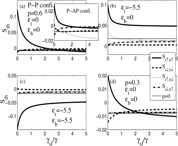
Figure 3(b) exhibits the results for the transport regime (1,0). It is obvious that the spin-resolved CCs are all positive due to dynamical channel anti-blockade; moreover, the dynamical spin blockade strongly enhances and weakly suppresses and in comparison with the results of the paramagnetic case. Therefore, the two effects are positively additive and they result in an enhanced positive CC for the transport regimes, (1,0) and (0,1). For the double occupation case (1,1), inter-dot Coulomb blockade is the dominant mechanism governing transport (over the dynamical spin blockade), giving rise to a negative value, but enhanced in magnitude, for the up-up CC [Fig. 3(c)].
On the contrary, the situation is quite different when one of the circuits is in the AP configuration. For the AP case, the fast electron has spin up at the input terminal but has spin down at the output terminal, leading to an accumulation of up spins and a rather weak bunching of tunneling events associated with down spin at the output terminal. When the top circuit is in the P configuration while the bottom circuit is in the AP configuration (P-AP configuration), we find very small positive values for and , and thus a vanishing for the transport regime (0,0) [inset of Fig. 3(a) and Fig. 2(d)]. A similar result is obtained when both circuits are in the AP configuration [Fig. 2(c)].
Our results show that a parallel-coupled QD in the P-P configuration is optimal for the occurrence of positive current CC: in the Coulomb anti-blockade regimes, (1,0) and (0,1), the maximum value of the CC can be nearly two times higher than that of the paramagnetic case. For instance, with , while with and with . In the Coulomb blockade regime, (0,0), the current CC can be for and for . The sign-change of the current CC between different output terminals due to dynamical spin blockade has not yet been observed experimentally for the original setup, a three-terminal QD with ferromagnetic leads.Cottet The main difficulty may be due to attaching the third ferromagnetic lead to the QD such that its tunnel coupling strength is comparable to that of the others. Our present proposal involves only a simpler element, an interacting QD connected to two ferromagnetic leads, which has already been realized experimentally,fif and it may provide a more accessible setup for the observation of positive CCs originating from dynamical spin blockade.
In conclusion, we have analyzed the gate-voltage dependent CC noise between two output terminals in tunneling through two capacitively coupled QDs connected to four independent ferromagnetic electrodes. We find a sign reversal of the zero-frequency CC noise in the dynamical channel blockade regime, if the polarization of the electrodes is sufficiently strong. Moreover, in the dynamical channel anti-blockade regimes, positive CC noises are obviously enhanced in comparison with the results of paramagnetic leads. These results may be ascribed to the joint effect of dynamical Coulomb blockade and dynamical spin blockade, and are found to be quite robust against the spin-flip relaxation.
This work was supported by Projects of the National Science Foundation of China, Specialized Research Fund for the Doctoral Program of Higher Education (SRFDP) of China, and the Program for New Century Excellent Talents in University (NCET). NJMH gratefully acknowledges support by DARPA grant No.HR0011-09-1-0008.
References
- (1) Ya.M. Blanter and M. Büttiker, Phys. Rep. 336, 1 (2000).
- (2) T. Martin et al.,in Quantum Noise in Mesoscopic Physics, edited by Yu.V. Nazarov, NATO Science Series II Vol. 97 (Kluwer, Dordrecht, 2003).
- (3) M. Büttiker, Phys. Rev. Lett. 65, 2901 (1990); Phys. Rev. B 46, 12 485 (1992).
- (4) M. Henny, S. Oberholzer, C. Strunk, T. Heinzel, K. Ensslin, M. Holland, and C. Schönenberger, Science 284, 296 (1999); W.D. Oliver, J. Kim, R.C. Liu, and Y. Yamamoto, Science 284, 299 (1999); H. Kiesel, A. Renz, and F. Hasselbach, Nature 418 392, (2002); S. Oberholzer, E. Bieri, C. Schönenberger, M. Giovannini, and J. Faist, Phys. Rev. Lett. 96, 046804 (2006).
- (5) M.P. Anantram and S. Datta, Phys. Rev. B 53, 16 390 (1996); T. Martin, Phys. Lett. A 220, 137 (1996); J. Torres and T. Martin, Eur. Phys. J. B 12, 319 (1999); F. Taddei and R. Fazio, Phys. Rev. B 65, 134522 (2002).
- (6) A. Cottet, W. Belzig, and C. Bruder, Phys. Rev. Lett. 92, 206801 (2004); A. Cottet, W. Belzig, and C. Bruder, Phys. Rev. B 70, 115315 (2004).
- (7) A.M. Martin and M. Büttiker, Phys. Rev. Lett. 84, 3386 (2000).
- (8) S.-T. Wu and S. Yip, Phys. Rev. B 72, 153101 (2005).
- (9) D.T. McClure, L. DiCarlo, Y. Zhang, H.-A. Engel, C.M. Marcus, M.P. Hanson and A.C. Gossard, Phys. Rev. Lett. 98, 056801 (2007).
- (10) S. Haupt, J. Aghassi, M.H. Hettler, and G. Schön, cond-mat/0802.3579 (2008).
- (11) A.N. Pasupathy, R.C. Bialczak, J. Martinek, J.E. Grose, L.A.K. Donev, P.L. McEuen, and D.C. Ralph, Science 306, 86 (2004); S. Sahoo, T. Kontos, J. Furer, C. Hoffmann, M. Graber, A. Cottet, and C. Schönenberger, Nat. Phys. 1, 99 (2005); R.S. Liu, D. Suyatin, H. Pettersson, and L. Samuelson, Nanotechnology 18, 055302 (2007); K. Hamaya, M. Kitabatake, K. Shibata, M. Jung, M. Kawamura, K. Hirakawa, T. Machida, T. Taniyama, S. Ishida, and Y. Arakawa, Appl. Phys. Lett. 91, 232105 (2007); J. Hauptmann, J. Paaske, and P. Lindelof, Nat. Phys. 4, 373 (2008).
- (12) Bing Dong, H.L. Cui, and X.L. Lei, Phys. Rev. B 69, 035324 (2004).
- (13) A.N. Korotkov, Phys. Rev. B 49, 10381 (1994); S. Hershfield, J.H. Davies, P. Hyldgaard, C.J. Stanton, and J.W. Wilkins, Phys. Rev. B 47, 1967 (1993); U. Hanke, Yu.M. Galperin, K.A. Chao, and N. Zou, Phys. Rev. B 48, 17209 (1993).
- (14) I. Djuric, Bing Dong, H.L. Cui, IEEE Transactions on Nanotechnology 4, 71 (2005); Appl. Phys. Lett. 87, 032105 (2005); J. Appl. Phys. 99, 063710 (2006).