Steering plasmodium with light:
Dynamical programming of Physarum machine
Abstract
A plasmodium of Physarum polycephalum is a very large cell visible by unaided eye. The plasmodium is capable for distributed sensing, parallel information processing, and decentralized optimization. It is an ideal substrate for future and emerging bio-computing devices. We study space-time dynamics of plasmodium reactiom to localised illumination, and provide analogies between propagating plasmodium and travelling wave-fragments in excitable media. We show how plasmodium-based computing devices can be precisely controlled and shaped by planar domains of illumination.
keywords:
Physarum polycephalum, wave, Oregonator, photo-response1 Introduction
At one phase of its life-cycle Physarum polycephalum111Order Physarales, subclass Myxogastromycetidae, class Myxomecetes lives as a huge single cell with many diploid nuclei. Such a life-form is called plasmodium. The plasmodium feeds on bacteria, spores and other microbial creatures. When foraging for its food the plasmodium propagates towards sources of food particles, surrounds them, secretes enzymes and digests the food. Typically the plasmodium forms a congregation of protoplasm in a food source it occupies. When several sources of nutrients are scattered in the plasmodium’s range, the plasmodium forms a network of protoplasmic tubes connecting the masses of protoplasm at the food sources.
Nakagaki et al [20, 21, 22] showed that the topology of the plasmodium’s protoplasmic network optimizes the plasmodium’s harvesting on distributed sources of nutrients and makes more efficient flow and transport of intra-cellular components. The plasmodium is considered as a parallel computing substrate complementary [3] to existing massive-parallel reaction-diffusion chemical processors [2]. The plasmodium functions as a parallel amorphous computer with parallel inputs. Such a parallel biological computer takes data in a form of spatially distributed sources of nutriets, and represents results of computation by configuration of its entire body and protoplasmic veins. The plasmodium is capable for a approximation of shortest path, computation of planar proximity graphs and plane tessellations, primitive memory and decision-making.
In [4] we shown that the plasmodium of Physarum polycephalum is a general purpose computing machine. This is because plasmodium implements the Kolmogorov-Uspensky (KUM) machine [17, 36] in its foraging behaviour. The KUM is a mathematical machine in which the storage structure is an irregular graph. The KUM is a forerunner and direct ‘ancestor’ of Knuth’s linking automata [16], Tarjan’s reference machine [33], and Schönhage’s storage modification machines [26, 27]. The storage modification machines are basic architectures for random access machines, which are the basic architecture of modern-day computers. The plasmodium-based implementation of KUM [4] is a first-ever biological prototype of a general purpose computer.
The key component of the KUM is an active zone [17, 36], which may be seen as a computational equivalent to the head in a Turing machine. Physical control of the active zone is of utmost importance because it determines functionality of the biological storage modification machine. In present paper we experimentally demonstrate that propagation of KUM’s active zone can be tuned by localized domains of illumination.
The plasmodium of Physarum exhibits negative phototaxis. General understanding of the plasmodium response to light is that the plasmodium moves away from light when it can and switches to another phase of its life cycle or undergoes phragmentation when it could not escape light. If plasmodium, particularly the starving one [13], is subjected to high intensity of light the plasmodium turns into a sporulation phase [25]. There are evidences that phytochromes are involed in the light-induced sporulation [32] and sporulation morphogene is transferred by protoplasmic streams to all parts of the plasmodium [14].
Photofragmentation is another physiological response to strong and unavoidable illumination. When plasmodium is illuminated by ultraviolet or blue monochromatic light, in hostile environment of laboratory conditions, it breaks into many equally sized fragments (each fragment contains around eight nuclei) [15]. The fragmentation is transient and after some time the fragments merge back into a fully functional plasmodium.
In the paper we focus on photomovement, the less drastic response to illumination than two scenarios mentioned above. Plasmodium of Physarum polycephalum exhibits most pronounced negative phototaxis to blue and white light [9, 30]. The illumination increase causes changes in the plasmodium oscillatory activity, degree of changes is proportional to a distance from the light source [37, 11]. Exact mechanisms of the response to light is yet unknown. There is however a few phenomena uncovered in experiments. First is presence of phytochrome-like pigments [15], which might be primary receptors of illumination. The light-response of the pigments triggers a chain of biochemical process [29]. These processes include increase in activity of isomerase enzymes [31], changes in mytochondrial respiration [18], and spatially distributed oscillations in ATP concentrations [35].
Nakagaki et al [24, 23] undertook first ever experiments on shaping plasmodium behavior with illumination. They discovered that protoplasm streaming oscillations of plasmodium can be tuned by, or relatively synchronized with, periodic illumination [24]. They also demonstrated that plasmodium optimizes its protoplasmic network structure in the field with heterogeneous illumination [23]: thickness of protoplasmic tubes in illuminated areas are less then thickness of tubes in shaded areas [23]. These indicate that illumination gradients could be a convenient tool to input instructions to different parts of Physarum machines in parallel. Several basic questions need to be answered. What exactly a pseudopodium or a migrating Physarum do when approach an illuminated domain? How light can be used to program plasmodium movements? What types of plasmodium reflections can be implemented using light-mirrors? Can we shape the plasmodium’s network structure by heterogeneous illumination? In the paper we present experimental and theoretical findings we obtained while trying to answer the questions.
2 Methods
The plasmodia of Physarum polycephalum222Culture of Physarum polycephalum was kindly supplied by Dr. Soichiro Tsuda were cultured on wet paper towels, fed with oat flakes, and moistened regularly. We subcultured the plasmodium every 5-7 days.
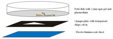
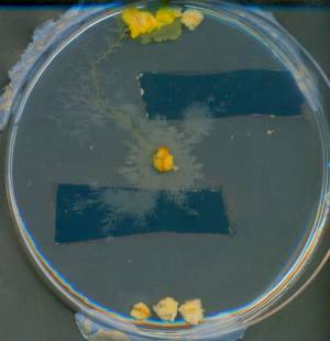
Experiments on controlling the plasmodium with light were undertaken in standard Petri dishes, 9 cm in diameter. A substrate was 2% agar gel. Light-obstacles, or illumination domains, were implemented using electro-luminescent sheets 333Manufacturer Seikosha, supplier RS Components Ltd Birchington Road, Corby, Northants, NN17 9RS, UK. Based on previous works in negative phototaxis of Physarum we have choosen blue illuminating sheets. The nominal sheets brightness (at 110 V, 400 Hz AC) is 73 cd/m2 (blue). The electro-luminiscent sheets did not produre heat, therefore can be positioned in close contact with growing substrate. Masks were prepared from black plastic: rectangles and triangles were cut in the plastic. When a mask is placed on top of the electro-luminiscent sheet, the light is passed only throught the cuts (Fig. 1)444Pictures quality is dramatically reduced. See version published in the Journal for high-resolution pictures..
The experiments were conducted in a room with diffusive light of 3-5 cd/m, 22oC temperature. In each experiment an oat flake colonized by the plasmodium was placed on one side of a Petri dish, and few oat flakes without plasmodium at the opposite side of the Petri dish (to shape directional propagation of the plasmodium). Petri dishes with plasmodium were periodically scanned on a standard HP scanner. The only editing done to scanned images is colour enhancement: increase of saturation and contrast.
When plasmodium is cultivated on a non-nutrient substrate a profile of its pseudopodium’s propagating tip, and particularly the profile of the plasmodium propagating as a whole, is isomorphic to shapes of and behaves as wave-fragments in sub-excitable reaction-diffusion chemical media, see details in [5, 6]. Therefore we simulated propagation of the plasmodium with two-variable Oregonator equation [12, 34], used originally to simulate light-sensitive Belousov-Zhabotinsky reaction with applied gradients of illumination [8, 19]:
In terms of Belousov-Zhabotisnky reaction the variables and represent local concentrations of bromous acid HBrO2 and the oxidized form of the catalyst ruthenium Ru(III), sets up a ratio of time scale of variables and , is a scaling parameter depending on reaction rates, is a stoichiometric coefficient, is a light-induced bromide production rate proportional to intensity of illumination. The is an excitability parameter. Moderate intensity of light will facilitate excitation process, higher intensity will produce excessive quantities of bromide which suppresses the reaction. There is no diffusion term for because we assume the catalyst is immobilized.
To integrate the system we used Euler method with five-node Laplasian operator, null boundary conditions. time step and grid point spacing , with the following parameters: , , , , , .
Illuminated domain (light obstacle) of the experimental space was simulated by higher values of the parameter : if given point belongs to then (the medium inside the light obstacle becomes non-excitable) otherwise . For such set of parameters the model represents a sub-excitable medium (at the edge between of non-excitability and full excitability). The sub-excitable media exhibits self-localized excitations. A local disturbance leads to formation of traveling excitation wave-fragments which preserve their shape for finite period of time and then either expand or collapse. The traveling wave-fragments imitate propagating plasmodium.
3 Trees and waves
There are two distinct forms of the plasmodium: a protoplasmic tree and a traveling localizations. The protoplasmic tree is formed when plasmodium forages the space by sprouting pseudopodia in various directions. The pseudopodia remain connected to original location (and still main “body”) of the plasmodium by protoplasmic tubes. In certain situations (exact characteristics of such situations might be a subject of further studies) the plasmodium leaves its original location and propagates as a whole on the substrate. When the plasmodium propagates as a whole (migrating plasmodium) it has shape of a wave-fragment traveling in the a sub-excitable medium. The boundary between two morphologies may be fuzzy, and very often we can observe wave-fragment like shapes of pseudopodia, and gradual transitions between tree-like and wave-fragment like morphology.
/ScanImage001.jpg)
/ScanImage002.jpg)
/ScanImage003.jpg)
/ScanImage004.jpg)
/ScanImage005.jpg)
/ScanImage006.jpg)
/ScanImage007.jpg)
/ScanImage008.jpg)
An example of the “tree to wave-fragment” transformation is provided in Fig. 2. An oat flake colonized by plasmodium is placed in south part of a Petri dish (Fig. 2a). The plasmodium sprouts several pseudopodia exploring the space (Fig. 2a). The protoplasmic branches die out when encounter illuminated domains (Fig. 2bc). A group of branching pseudopodia tries to find a way around the triangular light obstacle (Fig. 2c) but eventually abandons the attempt (Fig. 2d).
By that time bacteria on the original oat flakes are exhausted and the plasmodium switches to its migration phase (Fig. 2d). The plasmodium abandons its original oat flake and starts propagating as a whole along the eastern wall of the Petri dish (Fig. 2ef). A typical wave-fragment of the propagating plasmodium is formed (Fig. 2g) which heads toward the source of nutrients (a group of oat flakes in the northern part of Petri dish). Eventually the plasmodium reaches new source of nutrients (Fig. 2h).
When the plasmodium propagates as a whole it looks like and behaves like a wave-fragment in sub-excitable medium [5, 6]. Moreover, migrating plasmodium is more sensitive to potential environment threats than just propagating pseudopodia. This is because a protoplasm in pseudopodia can always be retracted back to main body of plasmodium, thus pseudopodia can “take risks”. The migrating plasmodium is more vulnerable, because any “mis-calculation” in choosing its migration route may lead to disaster.
4 Diverting plasmodium
In an ideal situation the plasmodium propagates as wave-fragment and — unless encounters an obstacle on the way — keeps its shape and velocity vector conserved. If a proximal part of the plasmodium wave comes upon a highly illuminated domain, frequency of protoplasm oscillations in this domain increases. Due to a difference in the protoplasm oscillation frequency the plasmodium wave slightly turns to the side with less oscillating protoplasm.
Finding 1
One can steer propagating plasmodium using light obstacles.
/ScanImage003.jpg)
/ScanImage004.jpg)
/ScanImage005.jpg)
/ScanImage006.jpg)
/scheme03.jpg)
/scheme04.jpg)
/scheme05.jpg)
/scheme06.jpg)
A deflection of the plasmodium wave by light triangle is demonstrated in Fig. 3. The plasmodium wave propagates North-North-East (Fig. 3ae). The plasmodium hits a light triangle with its western side (Fig. 3bf). The light increases frequency of oscillations in the illuminated part of the plasmodium. The plasmodium wave turns eastward (Fig. 3cg) and travels in the new direction until hits the dish’s wall (Fig. 3cdh).
/ScanImage009.jpg)
/ScanImage010.jpg)
/scheme009.jpg)
/scheme010.jpg)
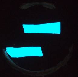
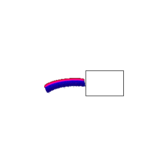
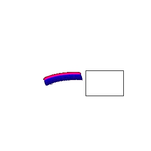
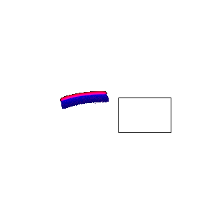
The plasmodium may not reflect from light obstacle immediately. After encountering even highly illuminated area the plasmodium wave carries on traveling in the original direction and only after passing obstacle starts diverting. Such example of delayed reaction to illumination is shown in Fig. 4. Plasmodium wave, originated from the plasmodium colonizing a group of flakes in northern part of the dish, travels South (Fig. 4ac). The wave passes through rectangular illuminated area without any immediate reaction (Fig. 4a). The response occurs several hours later. The plasmodium steers South-West (Fig. 4bd). Note that the plasmodium is not diverted by second (lying southward) light rectangle, because when diversion happens the plasmodium is far from the second light rectangle.
/ScanImage006.jpg)
/ScanImage007.jpg)
/scheme006.jpg)
/scheme007.jpg)
Another example of the steering by light obstacles is shown in Fig. 5. The plasmodium wave, heading North, enters the illuminated rectangular area (Fig. 5ac). The wave is slightly displayed towards eastern side of the light rectangle. Due to differences in light-induced oscillation of protoplasm the plasmodium turns North-East and continues traveling in this direction till collides with a wall of the Petri dish (Fig. 5bd).
Finding 2
Combining light obstacles and sources of nutrients (chemo-attractants) one can implement precise control of plasmodium waves.
/ScanImage001.jpg)
/ScanImage002.jpg)
/ScanImage003.jpg)
/scheme001.jpg)
/scheme002.jpg)
/scheme003.jpg)
The plasmodium is attracted to oat flakes populated with bacteria: we experimentally demonstrated that the plasmodium senses and reacts to sources of nutrients placed as far as 3-4 cm away of the plasmodium. The plasmodium ‘ascents’ along gradients of the attractants till it reaches sources of nutrients. By placing light obstacles in the attractive field we can tune and shape trajectory of the plasmodium motion. For example, the plasmodium shown in Fig. 6 is reflected eastward by first illuminated rectangle it encounters (Fig. 6ad). Later the plasmodium turns North being attracted to oat flakes in Northern part of the Petri dish. The plasmodium is directed westward by the second illuminated rectangle (Fig. 6be). However it does not continue West but turns North again to reach the sources of nutrients (Fig. 6cf).
5 Multiplying plasmodium waves
Finding 3
A propagating plasmodium wave or a pseudopodium can be split by suitably shaped domain of illumination.
/ScanImage002.jpg)
/ScanImage003.jpg)
/ScanImage004.jpg)
/splittingtrianglescheme01.jpg)
/splittingtrianglescheme02.jpg)
/splittingtrianglescheme03.jpg)
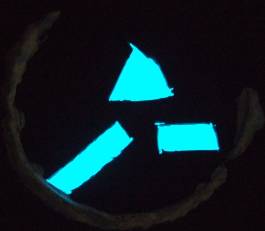
In some situation propagating plasmodium hits a light obstacle which is small enough to divert the whole plasmodium wave. If parts of the plasmodium wave remain outside the illuminated shape, these parts continue travel as “independent” plasmodium waves. Thus the plasmodium wave will be split into two waves. An example is provided in Fig. 7. In this particular experiment the plasmodium wave is comprised of several pseudopodia moving together in a close group. On its way toward source of nutrients the wave runs across illuminated triangle (Fig. 7ad). The pseudopodia try to steer away from the source of light and move toward western and eastern sides of the illuminated triangle (Fig. 7be). Eventually two separate groups of pseudopodia are formed, one group travels North-West, second group moves North-East (Fig. 7be).
6 Optimization of foraging in presence of illumination-obstacles
Finding 4
When Physarum scouts a space with pseudopodia it abandons the pseudopodia which encounter illuminated domains and sprouts new pseudopodia in the less illuminated areas and towards the sources of nutrients.
Nakagaki et al [23] already demonstrated that the plasmodium optimizes its protoplasmic network in presence of light, namely the plasmodium reduces number and size of protoplasmic tubes exposed to light. In present paper we do not focus on optimization and do not provide statistical evidences but rather few morphological examples of how growing protoplasmic network is shaped by illuminated domains.
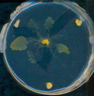
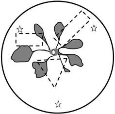
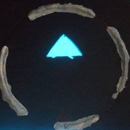
Most typical example is shown in Fig. 8. Initially an oat flake colonized by the plasmodium is placed in a central part of the Petri dish (Fig. 8ac). Three intact oat flakes are placed near the Petri dish wall so they form vertexes of a triangle centered in the initial position of the plasmodium. The plasmodium sprouts several pseudopodia heading towards the oat flakes. Most of the pseudopodia encounter illuminated areas and seize propagation. The pseudopodium propagating East-South-East manages to avoid illuminated areas and eventually reaches North-East oat flake (Fig. 8bd).
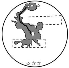
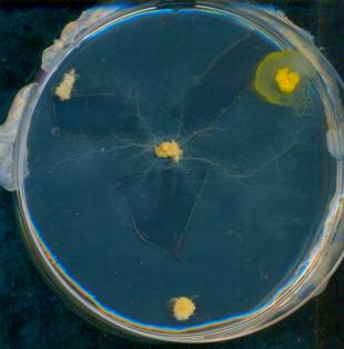
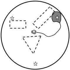
There are evidences that the plasmodium may “evaluate” size of the light obstacles by sprouting pseudopodia in several directions, integrating information about size of obstacles (possible via protoplasm oscillation frequencies) and then making a decision about where to sprout further pseudopodia. An example of such decision making is provided in Fig. 9. In the experiment reported the plasmodium was placed in the center of a Petri dish, and additional oat flakes were placed in North and South poles of the dish. The plasmodium sprouts several pseudopodia to explore the space. Some of the pseudopodia encounter illuminated areas. The illuminated area south of the plasmodium is larger than the illuminated area north of the plasmodium. Therefore the plasmodium does not sprout any more pseudopodia southward but produces a protoplasmic branch growing North. This pseudopodium reaches the south source of nutrients (Fig. 9).
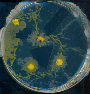
Such mechanism of scouting allow plasmodium to pre-shape its foraging network. When eventually plasmodium spans all sources of nutrients with its protoplasmic network major tubes of the network become positioned in the non-illuminated areas (Fig. 10).
7 Simulating plasmodium in two-variable Oregonator
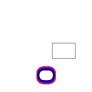
Striking similarity in behaviour of the plasmodium and wave-fragments in sub-excitable media has been found in our previous papers [5, 6]. Oregonator based model of the plasmodium waves impeccably matches our experimental results. An example of simulation is provided in Fig. 11.
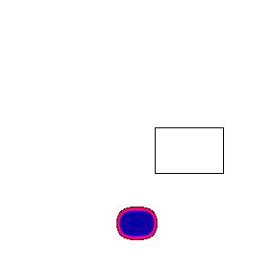
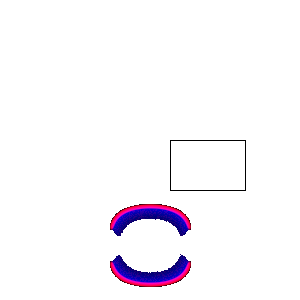
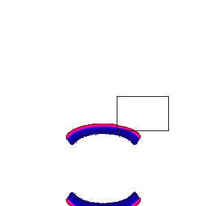
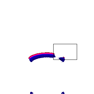
At the beginning of experiments a piece of plasmodium is simulated by exciting the medium with ellipse-shaped stimulus (Fig. 11a): the medium is perturbed by an initial excitation, when sites are assigned each. The perturbation generates an ellipse-shaped excitation wave. Due to sub-excitability of the simulated medium, the initially circular wave front (Fig. 11b) breaks into two wave fragments. One wave travels North, another wave South (Fig. 11c–e). We discard South travelling wave. When the Eastern part of the North travelling wave enters illumination area it becomes inhibited and gradually disappears (Fig. 11ef). The remaining part of the wave continues its travel as an individual wave, propagating North-North-West (Fig. 11g–i).


Simulation results for wave splitting are shown in Fig. 12. An ellipse-shaped zone of initial excitation (Fig. 12a) produces two wave-fragments travelling North and South (Fig. 12bc). We are concerneted with the fragment propagating North (Fig. 12de). When the wave-fragment reaches illuminated triangle the part of the wave inside the triangle extinguishes due to excitability inhibited by light (Fig. 12fg). In the result of the inhibition two separate wave-fragments are formed. One wave-fragment travels South-West another travels South-East (Fig. 12hi).
8 Routing signals in Physarum machine
Kolmogorov-Uspensky Machine (KUM) is defined on a labeled undirected graph (storage structure) with bounded degrees of nodes and bounded number of labels [17, 36]. KUM executes the following operations on its storage structure: select an active node in the storage graph; specify local active zone, i.e. the node’s neighborhood; modify the active zone by adding a new node with the pair of edges, connecting the new node with the active node; delete a node with a pair of incident edges; add/delete the edge between the nodes. A program for KUM specifies how to replace the neighborhood of an active node (i.e. occupied by an active zone) with a new neighborhood, depending on the labels of edges connected to the active node and the labels of the nodes in proximity of the active node [10].
Physarum machine is a biological implementation of KUM, where a node of the storage structure is represented by a source of nutrients (e.g. an oat flake); an edge connecting two nodes is a protoplasmic tube linking two sources of nutrients corresponding to the nodes; and, an active zone is domain of space (which may include food sources) occupied by a propagating pseudopodium. A migrating plasmodium also represents an active zone.
In Physarum machine the computation is implemented by active zone, or several active zones. To make the computation process programmable one needs to find ways of sensible and purposeful manipulation with the active zones. In [7] we experimentally demonstrated how active zones can be manipulated by dynamical addition of nutrients. Programming with nutrients is not really efficient, because once the source of nutrients placed in the computing space, it irreversibly changes configuration of attracting fields. Light inputs allow us for on-line reconfiguration of obstacles and thus provide more opportunities for embedding complex programs in Physarum machines.
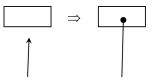
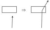
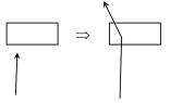
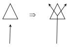
Basic operations of routing active zones are shown in Fig. 13.
Operation Erase removes, or permanently deactivates, active zone (Fig. 13a). The operation is implemented by placing large enough – so there is no chance of the plasmodium wave to escape the shaded area – domain of illumination in front of the traveling zone . The plasmodium wave then gradually disappears. The operation is experimentally exemplified in Fig 8, where few active zones are canceled by rectangles of illumination.
Operation Left rotates velocity vector of zone on angle , ; for Rigth (Fig. 13bc). Exact value of rotation angle depends on many factors, including size of illumination domain, size of traveling zone , humidity, overall illumination, and fitness of the plasmodium. Based on few successful experiments on rotation of plasmodium waves, we could say that .
Operation Multiply (Fig. 13bc) splits traveling plasmodium wave into zones and deviated slightly left and right, comparing to original direction of ’s travel.
9 Discussion
In laboratory experiments with plasmodium of Physarum polycephalum and in computer simulations we discovered that propagating plasmodium interacts with illuminated domains similarly to travelling wave-fragments in excitable media. We demonstrated that plasmodium waves can be diverted, annihilated and split by properly arranged shapes of illumination. The light-induced diversion of the plasmodium waves can be used as operations of signal and process routing in plasmodium-based implementations of general purpose storage machines [4]. Future studies will concern with programming Physarum machines by combination of chemoattractants’ gradients and illumination domains.
Usually quite high intensity of illumination is used in studies of Physarum response [11, 23]. Thus in [11] reported threshold intensity for blue light is about 1,500 Lux. In our experiments the plasmodium was controlled by much less illuminated shapes, with maximum intensity of illumination of 50-70 Lux. This is why we did not observe strong photophobic reaction but rather gentle and often subtle changes in Physarum behavior. The moderate intensity of illumination used in our experiments shows that we can achieve purposeful behavior of the plasmodium with light stimulation without causing any adverse reactions.
Geometrically shaped domains of illumination, utilised in our experiments, provided sharp boundaries between illuminated and non-illuminated areas. They did not form smooth gradients of illumination. Also size of the illumination domains was the same order as a ‘wavelength’ of propagating plasmodium waves. These guaranteed that the illuminated shapes acted rather as reflectors, or mirrors, than sources of repelling fields. Therefore we envisage findings presented in the paper can be used in experimental implementation of collision-based computing schemes [1], where plasmodium waves represent quanta of information and illumination domains are used to route momentary wires (trajectories) of the information quanta.
References
- [1] Adamatzky A. (Editor) Collision Based Computing, Springer, 2003.
- [2] Adamatzky A., De Lacy Costello B., Asai T. Reaction-Diffusion Computers, Elsevier, Amsterdam, 2005.
- [3] Adamatzky A. Physarum machines: encapsulating reaction-diffusion to compute spanning tree. Naturwisseschaften 94 (2007) 975–980.
- [4] Adamatzky A. Physarum machine: implementation of a Kolmogorov-Uspensky machine on a biological substrate. Parallel Processing Letters 17 (2007) 455–467.
- [5] Adamatzky A., De Lacy Costello B., Shirakawa T. Universal computation with limited resources: Belousov-Zhabotinsky and Physarum computers. Int. J. Bifurcation and Chaos (2008), in press.
- [6] Adamatzky A. If BZ medium did spanning trees these would be the same trees as Physarum built. Physics Letters A 373 (2009) 952–956.
- [7] Adamatzky A. and Jones J. Programming Physarum machines. J Natural Computation (2009), in press.
- [8] Beato V., Engel H. Pulse propagation in a model for the photosensitive Belousov-Zhabotinsky reaction with external noise. In: Noise in Complex Systems and Stochastic Dynamics, Edited by Schimansky-Geier L., Abbott D., Neiman A., Van den Broeck C. Proc. SPIE 5114 (2003) 353–362.
- [9] Bialczyk J. An action spectrum for light avoidance by Physarum Nudum plasmodia. Photochemistry and Photobiology 30 (1979) 301–303.
- [10] Blass A. and Gurevich Y. Algorithms: a quest for absolute definitions, Bull. Europ. Assoc.TCS 81 (2003) 195–225.
- [11] Block I. and Wohlfarth-Bottermann K. E. Blue light as a medium to influence oscillatory contraction frequency in physarum. Cell Biology International Reports 5 (1981) 73–81
- [12] Field R. J., Noyes R. M. Oscillations in chemical systems. IV. Limit cycle behavior in a model of a real chemical reaction. J. Chem. Phys. 1974;60:1877–84.
- [13] Guttes E., Guttes S. and Rusch H. P. Morphological observations on growth and differentiation of Physarum polycephalum grown in pure culture. Developmental Biology 3 (1961) 588–614.
- [14] Hildebrandt A. A morphogen for the sporulation of Physarum polycephalum detected by cell fusion experiments. Experimental Cell Research 167 (1986) 453–457.
- [15] Kakiuchi Y., Takahashi T., Murakami A. and Ueda T. Light irradiation induces fragmentation of the plasmodium, a novel photomorphogenesis in the true slime mold Physarum polycephalum: Action spectra and evidence for involvement of the Phytochrome. Photochemistry and Photobiology 73 (2001) 324- 329.
- [16] Knuth D. E. The Art of Computer Programming, Vol. 1: Fundamental Algorithms, Addison-Wesley, Reading, Mass. 1968.
- [17] Kolmogorov A. N., On the concept of algorithm, Uspekhi Mat. Nauk 8:4 (1953), 175–176.
- [18] Korohoda W., Shraideh Z., Baranowski Z. and Wohlfarth-Bottermann K. E. The blue-light reaction in plasmodia of Physarum polycephalum is coupled to respiration. Planta 158 (1983) 54-62.
- [19] Krug H. J., Pohlmann L., Kuhnert L. Analysis of the modified complete Oregonator (MCO) accounting for oxygen- and photosensitivity of Belousov-Zhabotinsky systems. J. Phys. Chem. 1990;94:4862–66.
- [20] Nakagakia T., Yamada H., Ueda T. Interaction between cell shape and contraction pattern in the Physarum plasmodium, Biophysical Chemistry 84 (2000) 195–204.
- [21] Nakagaki T., Smart behavior of true slime mold in a labyrinth. Research in Microbiology 152 (2001) 767- 770.
- [22] Nakagaki T., Yamada H., and Toth A., Path finding by tube morphogenesis in an amoeboid organism. Biophysical Chemistry 92 (2001) 47 -52.
- [23] Nakagaki T., Iima M., Ueda T., Nishiura y., Saigusa T., Tero A., Kobayashi R., Showalter K. Minimum-risk path finding by an adaptive amoeba network. Physical Review Letters 99 (2007) 068104.
- [24] Nakagaki T. Yamada H., Ueda T. Modulation of cellular rhythm and photoavoidance by oscillatory irradiation in the Physarum plasmodium. Biophysical Chemistry 82 (1999) 23–28.
- [25] Sauer H. W., Babcock K. L. and Rusch H. P. Sporulation in Physarum polycephalum: A model system for studies on differentiation. Experimental Cell Research. 57 (1969) 319–327.
- [26] Schönhage A. Real-time simulation of multi-dimensional Turing machines by storage modification machines, Project MAC Technical Memorandum 37, MIT (1973).
- [27] Schönhage, A. Storage modification machines. SIAM J. Comp., 9 (1980) 490–508.
- [28] Shraideh Z. A. Requirment of mitochondrial functions for blue light response in the plasmodium of Physarum polycephalum. Cell Biology International Reports 12 (1988) 253–262.
- [29] Schreckenbach T., Walckhoff B., and Verfuerth C. Blue-light receptor in a white mutant of Physarum polycephalum mediates inhibition of spherulation and regulation of glucose metabolism. Proc Natl Acad Sci USA 78 (1981) 1009- 1013.
- [30] Schreckenbach T. Phototaxis and photomorphogenesis in Physarum polycephalum plasmodia. In: Senger H. (Editor), Blue Light Effects in Biological Systems (Springer-Verlag, 1984), 464–475.
- [31] Krzysztof Staro a and Wojciech Wo nya Light-induced transient increase of the activity of topoisomerase I in plasmodia of Physarum polycephalum. International Journal of Biochemistry 24 (1992) 1717–1720.
- [32] Starostzik C. and Marwan W. A photoreceptor with characteristics of phytochrome triggers sporulation in the true slime mould Physarum polycephalum. FEBS Letters 370 (1995) 146—148.
- [33] Tarjan R. E. Reference machines require non-linear time to maintain disjoint sets, STAN-CS-77-603, March 1977.
- [34] Tyson J. J., Fife P. C. Target patterns in a realistic model of the Belousov Zhabotinskii reaction. J. Chem. Phys. 1980;73:2224–37.
- [35] Ueda T., Mori Y. and Kobatake Y. Patterns in the distribution of intracellular ATP concentration in relation to coordination of amoeboid cell behavior in Physarum polycephalum. Experimental Cell Research 169 (1987) 191–201.
- [36] Uspensky V.A. Kolmogorov and mathematical logic, The Journal of Symbolic Logic 57 (1992) 385–412.
- [37] Wohlfarth-Bottermann K. E. and Block I. The pathway of photosensory transduction in Physarum polycephalum. Cell Biology International Reports 5 (1981) 365–373.