Stable propagation of a modulated positron beam in a bent crystal channel
Abstract
The propagation of a modulated positron beam in a planar crystal channel is investigated. It is demonstrated that the beam preserves its modulation at sufficiently large penetration depths which opens the prospect of using a crystalline undulator as a coherent source of hard x-rays. This finding is a crucial milestone in developing a new type of lasers radiating in the hard x-ray and gamma-ray range.
pacs:
61.85.+p, 05.20.Dd, 41.60.-mIn this communication we study for the first time the evolution of a modulated particle beam in a bent planar crystal channel and demonstrate that a positron beam preserves its modulation at sufficiently large penetration depths, which opens the prospect of using a crystalline undulator as a coherent source of hard x-rays. Solving this problem is of crucial importance in the theory of the crystal undulator based laser (CUL) [1, 2, 3] — a new electromagnetic radiation source in hard x- and gamma-ray range.
Channelling takes place if charged particles enter a single crystal at small angle with respect to crystallographic planes or axes [4]. The particles get confined by the interplanar or axial potential and follow the shape of the corresponding planes and axes. This suggested the idea [5] of using bent crystals to steer the particles beams. Since its first experimental verification [6] the idea to deflect or extract high-energy charged particle beams by means of tiny bent crystals replacing huge dipole magnets has been attracting a lot of interest worldwide. Bent crystal have been routinely used for beam extraction in the Institute for High Energy Physics, Russia [7]. A series of experiments on the bent crystal deflection of proton and heavy ion beams was performed at different accelerators [8, 9, 10, 11, 12] throughout the world. The bent crystal method has been proposed to extract particles from the beam halo at CERN Large Hadron Collider [13] The possibility of deflecting positron [14] and electron [12, 15] beams has been studied as well.
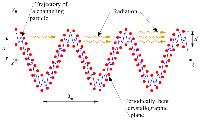
A single crystal with periodically bent crystallographic planes can force channelling particles to move along nearly sinusoidal trajectories and radiate in the hard x- and gamma-ray frequency range (see figure 1). The feasibility of such a device, known as the ’crystalline undulator‘, was demonstrated theoretically a decade ago [1] (further developments as well as historical references are reviewed in [16]). More recently, an electron based crystalline undulator has been proposed [17].
It was initially proposed to obtain sinusoidal bending by the propagation of an acoustic wave along the crystal [1, 2]. The advantage of this approach is its flexibility: the period of deformation can be chosen by tuning the frequency of the ultrasound. However, this approach is rather challenging technologically and yet to be tested experimentally. Several other technologies for the manufacturing of periodically bent crystals have been developed and tested. These include making regularly spaced grooves on the crystal surface either by a diamond blade [18, 19] or by means of laser-ablation [20], deposition of periodic Si3N4 layers onto the surface of a Si crystal [19], growing of Si1-xGex crystals[21] with a periodically varying Ge content [22, 23].
Experimental studies of the crystalline undulator are currently in progress. The first results are reported in [24] and [25].
The advantage of the crystalline undulator is in extremely strong electrostatic fields inside a crystal which are able to steer the particles much more effectively than even the most advanced superconductive magnets. This fact allows to make the period of the crystalline undulator in the range of hundreds or tens micron which is two to three orders of magnitude smaller than that of conventional undulator. Therefore the wavelength of the produced radiation (– being the Lorentz factor of the particle) can reach the (sub)picometer range, where conventional sources with comparable intensity are unavailable [26].
Even more powerful and coherent radiation will be emitted if the probability density of the particles in the beam is modulated in the longitudinal direction with the period , equal to the wavelength of the emitted radiation. In this case, the electromagnetic waves emitted in the forward direction by different particles have approximately the same phase [27]. Therefore, the intensity of the radiation becomes proportional to the beam density squared (in contrast to the linear proportionality for an unmodulated beam). This increases the photon flux by orders of magnitude relative to the radiation of unmodulated beam of the same density. The radiation of a modulated beam in an undulator is a keystone of the physics of free-electron lasers (FEL) [28, 29]. It can be considered as a classical counterpart of the stimulated emission in quantum physics. Therefore, if similar phenomenon takes place in a crystalline undulator, it can be referred to as the lasing regime of the crystalline undulator.
The feasibility of CUL radiating in the hard x-ray and gamma-ray range was considered for the fist time in [1, 2]. Recently, a two-crystal scheme, the gamma klystron, has been proposed [3].
A simplified model used in the cited papers assumed that all particle trajectories follow exactly the shape of the bent channel. In reality, however, the particle moving along the channel also oscillates in the transverse direction with respect to the channel axis (see the shape of the trajectory in figure 1). Different particles have different amplitudes of the oscillations inside the channel (figure 2, upper panel).
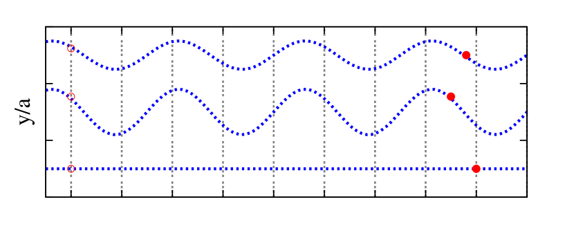
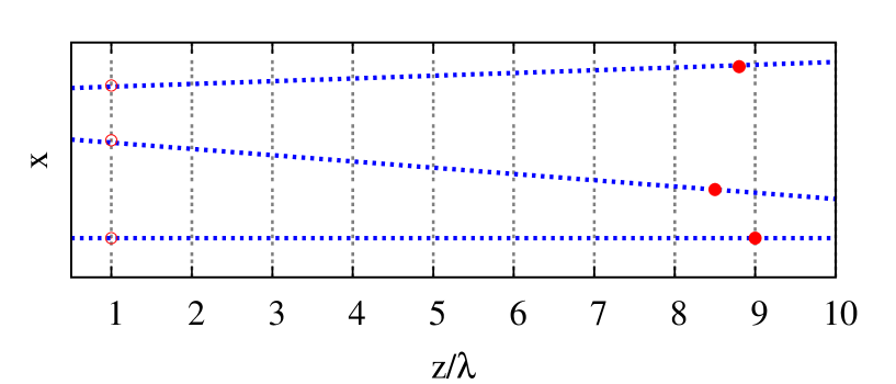
Similarly, the directions of particle momenta in plane are slightly different (figure 2, lower panel). Even if the speed of the particles along their trajectories is the same, the particles oscillating with different amplitudes or the particles with different trajectory slopes with respect to axis have slightly different components of their velocities along the channel. As a result, the beam gets demodulated. An additional contribution to the beam demodulation comes from incoherent collisions of the channelling particles with the crystal constituents.
In the case of an unmodulated beam, the length of the crystalline undulator and, consequently, the maximum accessible intensity of the radiation is limited by the dechannelling process. The channelling particle gradually gains the energy of transverse oscillation due to collisions with crystal constituents. At some point this energy exceeds the maximum value of the interplanar potential and the particle leaves the channel. The average penetration length at which this happens is known as the dechannelling length. The dechannelled particle no longer follows the sinusoidal shape of the channel and, therefore, does not contribute to the undulator radiation. Hence, the reasonable length of the crystalline undulator is limited to a few dechannelling lengths. A longer crystal would attenuate rather then produce the radiation. Since the intensity of the undulator radiation is proportional to the undulator length squared, the dechannelling length and the attenuation length are the main restricting factors that have to be taken into account when the radiation output is calculated.
In contrast, not only the shape of the trajectory but also the particles positions with respect to each other along axis are important for the lasing regime. If these positions become random because of the beam demodulation, the intensity of the radiation drops even if the particles are still in the channelling mode. Hence, it is the beam demodulation rather than dechannelling that restricts the intensity of the radiation of CUL. Understanding this process and estimating the characteristic length at which this phenomenon takes place is, therefore, a cornerstone of the theory of this new radiation source.
Let us consider the distribution of the beam particles with respect to the angle between the particle trajectory and the axis in the plane and the energy of the channelling oscillation 111We chose the system of units in such a way that the speed of light is equal to unity. Therefore, mass, energy and momentum have the same dimensionality. This is also true for length and time.. Here , and are, respectively, the particle momentum and its and components, is the interplanar potential which in the case of positive particles, which channel between the crystallographic planes, can be approximated by a parabola , and is the particle energy (we will consider only ultrarelativistic particles, therefore ). It can be shown that the evolution of this distribution in the crystal channel with the time and the longitudinal coordinate (penetration depth into the crystal along the curved channel) can be described by the following differential equation of Fokker-Planck type:
| (1) |
Here is the diffusion coefficient that is dominated by the scattering of the beam particles by lattice electrons. The particle longitudinal velocity averaged over the undulator period, , is given by
| (2) |
Equation (1) is akin to the equation describing dechannelling process (see e.g. [30]) and is derived in a similar way. The novel feature of it is the presence of time variable, which allows us to describe time dependent (modulated) beams. Additionally, it takes into account scattering in the plane.
If the beam is periodically modulated (bunched) the distribution can be represented as a Fourier series:
| (3) |
with to ensure the real value of the particle distribution. Since Eq. (1) is linear, it is sufficient to consider only one harmonic. Substituting one obtains
| (4) |
To simplify this equation, we make the substitution
and assume that the variation of within the modulation period is small: . This allows us to neglect the terms while keeping the terms . The resultant partial differential equation for can be solved by the method of separation of variables. Putting , we obtain a set of ordinary differential equations:
| (5) | |||||
| (6) | |||||
| (7) |
where , and do not depend on any of the variables , and and satisfy the condition
| (8) |
Eq. (5) has the form of the Schrödinger equation for the harmonic oscillator. Its eigenvalues and eigenfunctions are, respectively,
| (9) |
and
| (10) |
Here are Hermite polynomials.
Eq. (6) can be reduced to the Laguerre differential equation, so that its solution can be represented as
| (11) |
where is the Laguerre function222At nonnegative integer values of , the Laguerre function is reduced to the well known Laguerre polynomials. In the general case that is relevant to our consideration, it can be represented by an infinite series: . and is related to the eigenvalue via
| (12) |
The eigenvalues can be found by imposing the boundary conditions. The maximum energy of channelling oscillations in a bent channel with parabolic potential is given by , where is defined as a ratio of the centrifugal force to the maximum value of the interplanar force [16]. Therefore, the density boundary condition has the form:
| (13) |
Equation (13) has to be solved for . (the subscript enumerates different roots of the equation) and the result has to be substituted into (12).
It is convenient to represent the eigenvalues in the form
| (14) |
Here is the dechannelling length in a straight channel [30] ( is -th zero of the Bessel function ), is the corresponding Lindhard’s angle. We introduce the parameter
| (15) |
where is the spatial period of the modulation. The functions and can be represented as
| (16) | |||||
| (17) |
Here and are the cooresponding functions for the straight channel which are found by solving numerically Eq. (13) combined with (12).
Hence, the solution of Eq. (4) is represented as
| (19) |
where the coefficients are found from the particle distribution at the entrance of the crystal channel. Due to the exponential decrease of with (see (Stable propagation of a modulated positron beam in a bent crystal channel)), the asymptotic behaviour of at large is dominated by the term with and having the smallest value of the factor in the exponential. Therefore, at sufficiently large penetration depths, the particle distribution depends on as where is the newly introduced parameter — the demodulation length:
| (20) |
and is the phase velocity of the modulated beam along the crystal channel
| (21) |
This parameter is important for establishing the resonance conditions between the undulator parameters and the radiation wavelength. It will be analysed elsewhere.
In this communication we concentrate our attention on the demodulation length. It represents the characteristic scale of the penetration depth at which an initially modulated beam of channelling particles becomes demodulated.
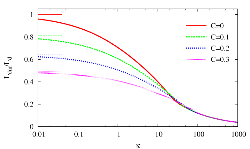
Figure 3 presents the dependence of the ratio on the parameter . At , the demodulation length approaches which is the dechannelling length in the bent crystal. It was proven for a number crystals channels [16] that the dechannelling length of positrons is sufficiently large to make the crystalline undulator feasible. Such a crystalline undulator becomes a CUL, i.e. it generates coherent radiation, provided that it is fed by a modulated positron beam and the beam preserves its modulation over the length of the crystal. This takes place if the demodulation length in the crystalline undulator is not much smaller than the dechannelling length. As is seen from the figure, the demodulation length is smaller than dechannelling length by only 20–30% at for varying between and . It noticeably drops, however, at . Hence, CUL is feasible if there exist crystal channels ensuering in the range of the photon energies above keV.333X-rays with photon energies of a few tens keV or less are strongly absorbed in the crystal. This puts the lower limit on the energies of the photons that can be generated by crystalline undulator based devices.
Indeed, such crystal channels do exist. Figure 4 shows the dependence of the parameter on the energy of the emitted photons for different crystal channels. The calculation was done for 1 GeV444Note that depends weakly (logarithmically) on the particle energy. Therefore, changing the beam energy by an order of magnitude would leave figure 4 practically unchanged. positrons using the formula for the dechannelling length from [16, 30]. As one sees from the figure, corresponds to keV for (100) and (110) planes in Diamond and (100) plane in Silicon. So these channels are the most suitable candidates for using in CUL. This is, however, not the case for a number of other crystals e.g. for graphite and tungsten having in the same photon energy range.
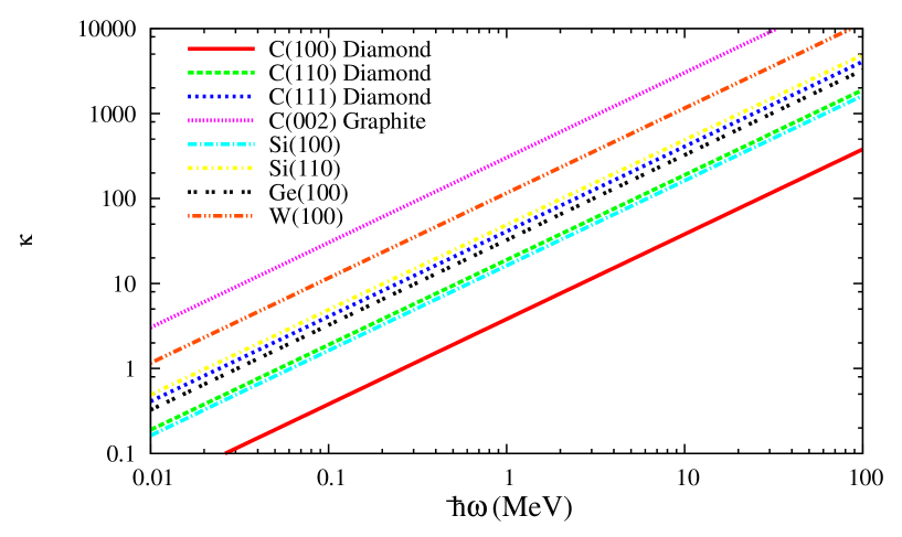
At MeV, becomes larger than for all crystal channels. This puts the upper limit on the energies of the photons that can be generated by CUL. It is expected to be most successful in the hundred keV range, while generating MeV photons looks more challenging.
According to our estimations, the brilliance as high as– can be obtained in a CUL fed by a completely modulated positron beam with current kA and particle density cm-3.
One may expect that the demodulation is not limited to the processes illustrated in figure 2. An additional contribution can come from the energy spread of the channelling particles, as it usually happens in ordinary FELs. In fact, the contribution of the energy spread to the beam demodulation on the distance of a few dechannelling lengths is negligible. It would be substantial if the relative spread of particle energies would be comparable to or larger than the ratio . The latter ratio, however, can not be made smaller than [16],555Note that the corresponding quantity in ordinary ultraviolet and soft x-ray FELs, the inverse number of undulator periods , is usually of the order of – [29]. That is why these FELs are so demanding to the small energy spread of the electron beam. while modern accelerators usually have a much smaller relative energy spread. The same is true for the energy spread induced by the stochastic energy losses of the channelling particles due to the interaction with the crystal constituents and the radiation of photon. It was shown in Ref.[31] that at initial energies of or smaller, the average relative energy losses of a positron in the crystalline undulator are smaller than . Clearly, the induced energy spread is safely below the ratio . From these reasons, we ignored energy spread of the particles in our calculations.
In conclusion, we have studied the propagation of a modulated positron beam in a bent planar crystal channel. It has been demonstrated that one can find the crystal channels in which the beam preserves its modulation at the penetration depths sufficient for producing coherent radiation with the photon energy of hundreds of keV. This opens the prospects for creating intense monochromatic radiation sources in a frequency range which is unattainable for conventional free electron lasers. Developing suitable methods of beam modulation would be the next milestone on the way towards this goal.
This work has been supported in part by the European Commission (the PECU project, Contract No. 4916 (NEST)) and by Deutsche Forschungsgemeinschaft.
References
- [1] A.V. Korol, A. V. Solov’yov and W. Greiner, J. Phys. G24 (1998), L45–53.
- [2] A.V. Korol, A. V. Solov’yov and W. Greiner, Int. J. Mod. Phys. E8 (1999) 49–100.
- [3] A. Kostyuk, A.V. Korol, A. V. Solov’yov, and W. Greiner, J. Phys. G36 (2009) 025107.
- [4] J. Lindhard, Kong. Danske Vid. Selsk. Mat.-Fys. Medd. 34 (1965) No. 14.
- [5] E.N. Tsyganov, TM-682, TM-684, Fermilab, Batavia (1976).
- [6] A.F. Elishev et al., Phys. Lett. B88 (1979) 387.
- [7] A.G. Afonin et al., Nucl. Instrum. Meth. B234 (2005) 14.
- [8] G. Arduini et al., Phys. Lett. B422 (1998) 325.
- [9] W. Scandale et al., Phys. Rev. ST Accel. Beams 11 (2008) 063501.
- [10] R.A. Carrigan et al., Phys. Rev. ST Accel. Beams 5 (2002) 043501.
- [11] R.P. Fliller et al., Phys. Rev. ST Accel. Beams 9 (2006) 013501.
- [12] S. Strokov et al., J. Phys. Soc. Jap. 76 (2007) 064007.
- [13] E. Uggerhøj and U.I. Uggerhøj, Nucl. Instrum. Meth. B234 (2005) 31.
- [14] S. Bellucci et al., Nucl. Instrum. Meth. B252 (2006) 3.
- [15] S. Strokov et al., Nucl. Instrum. Meth. B252 (2006) 16.
- [16] A.V. Korol, A. V. Solov’yov and W. Greiner, Int. J. Mod. Phys. E13 (2004) 867–916.
- [17] M. Tabrizi, A.V. Korol, A. V. Solov’yov and W. Greiner, Phys. Rev. Lett. 98 (2007) 164801.
- [18] S. Bellucci et al., Phys. Rev. Lett. 90 (2003) 034801.
- [19] V. Guidi et al., Nucl. Inst. and Meth. B234, (2005) 40.
- [20] P. Balling et al., Nucl. Inst. and Meth. B267 (2009) 2952.
- [21] M. B. H. Breese, Nucl. Inst. and Meth. B132 (1997) 540.
- [22] U. Mikkelsen and E. Uggerhøj, Nucl. Inst. and Meth. B160 (2000) 435.
- [23] A.V. Korol, W. Krause, A. V. Solov’yov, and W. Greiner Nucl. Inst. and Meth. A483 (2002) 455.
- [24] V. T. Baranov et al., Nucl. Instrum. Meth. B252 (2006) 32.
- [25] H. Backe, P. Kunz, W. Lauth and A. Rueda, Nucl. Instrum. Meth. B266 (2008) 3835.
- [26] A.V. Korol, A. V. Solov’yov and W. Greiner, in: W. Greiner, J. Reinhardt (Eds.), Topics in Heavy Ion Physics - Proceedings of the Memorial Symposium for Gerhard Soff, Frankfurt am Main, Germany, April 25-28, EP Systema, Budapest, 2005, pp. 73–86.
- [27] V. L. Ginzburg, Izv. Akad. Nauk. SSSR, Ser. Fiz. 11 (1947) 165–182.
- [28] J. M. J. Madey, J. Appl. Phys. 42 (1971) 1906–1913.
- [29] P. Schmüser, M. Dohlus, J. Rossbach, Ultraviolet and Soft X-Ray Free-Electron Lasers,Springer, Berlin Heidelberg, 2008.
- [30] V. M. Biruykov, Yu. A. Chesnokov, V. I. Kotov, Crystal Channelling and its Application at High-Energy Accelerators, Springer, Berlin Heidelberg New York, 1996.
- [31] A.V. Korol, A. V. Solov’yov and W. Greiner, Int. J. Mod. Phys. E9 (2000) 77.