CORE-TUBE MORPHOLOGY OF MULTIWALL CARBON NANOTUBES
Abstract
The present paper investigates the cross-sectional morphology of Multiwalled Carbon Nanotubes (MWNTs) restrained radially and circumferentially by an infinite surrounding elastic medium, subjected to uniform external hydrostatic pressure. In this study, a two-dimensional plane strain model is developed, assuming no variation of load and deformation along the tube axis. We find some characteristic cross-sectional shapes from the elastic buckling analysis. The effect of the surrounded elastic medium on the cross-sectional shape which occurs due to pressure buckling is focused on by the comparison with the shape for no elastic medium case in our discussion. It is suggested that in no embedded elastic medium cases, the cross-sectional shapes of inner tubes maintain circle or oval; on the other hand, an embedded medium may cause inner tube corrugation modes especially when the number of shells for MWNTs is small.
keywords:
carbon nanotube; cross-sectional deformation; hydrostatic pressure1 Introduction
Multiwalled carbon nanotubes (MWNTs) consist of graphene sheets wrapped up to form a series of concentric cylindrical shells[1, 2]. The number of shells in a MWNT ranges from 2 to more than 100, and they mutually interact via van der Waals (vdW) forces. Of interest is the feature that internal structures of MWNTs, like differences in diameters and chiralities between consecutive shells, are responsible for electronic[3, 4, 5, 6, 7, 8, 9] and optical[10, 11, 12, 13, 14, 15] properties of the systems. Therefore, better understandings of their cross-sectional deformation driven by external forces would be important for developing various MWNT-based applications involving sensors[16, 17] and actuators [18]. Nevertheless, most of earlier studies have dealt only with single-walled carbon nanotubes, in which simple radial collapse under pressures of the order of a few GPa was observed [19, 20].
Intuitively, the core-shell structure of a MWNT is expected to enhance its radial stiffness, as restoring forces exerted on pairs of neighboring shells buffer against cross-sectional deformation. This conjecture is, nevertheless, not obvious when . For the latter case, outside shells have large diameters that lead to mechanical instability, whereas inside shells keep the radial rigidity due to their small diameters. Such the discrepancy in the radial stiffness between outside and inside shells implies a new class of cross-sectional deformation induced by hydrostatic pressure. Another interesting issue is the radial and circumrerential stiffness of MWNTs embedded in an elastic medium. When applying an external force to the host medium of elastic composite embedding MWNTs, then a restoring force acts on the outermost surface of MWNTs. This restoring force will tend to remain the circular geometry of the outermost shell of each dispersed MWNT; this is in contrast with the previous case where the outermost shell become softened. Exploring the cross-sectional morphology of embedded MWNTs will provide useful information for developing nanofluidic [21, 22, 23, 24, 25] or nanoelectrochemical [26, 27] devices whose performance depend crucially on the geometry of the inner hollow cavity of nanotubes.
In this article, we analytically demonstrate the characteristic cross-sectional morphology of MWNTs with and without embedded elastic medium under external pressure. A two-dimensional plane strain model is developed, assuming no variation of load and deformation along the tube axis. It has been found that the existence of the surrounded elastic medium crucially affect the cross-sectional shape under buckling state. Some examples on the interesting cross-sectional shapes are introduced and brief discussions on these phenomena are also given.
2 Method
We have employed the continuum model of MWNTs[28, 29, 30, 31, 32] that enables to deduce the stable cross-sectional geometry under pressure. Though atomistic simulations are realistic and accurate, the computational cost associated is huge. This has encouraged the use of continuum models in various fields to study mechanical properties of MWNTs, together with discussions on the validity of the models[33, 34, 35, 36].
In the continuum model, a MWNT is mapped onto a set of concentric cylindrical shells with thickness , wherein the th shell has the radius . The mechanical energy of a MWNT per unit axial length is written as
| (1) |
The first term represents the deformation energy, in which , is the extensional strain of a circumferential line element; is a radial coordinate measured from the centroidal curve of the th shell, is a circumferential coordinate, and with the Young modulus TPa and Poisson’s ratio of MWNTs. The second term in Eq. (1) is the interaction energy of all adjacent pairs of shells described by , where describes the radial deformation of the th shell, and the summation is taken for all neighboring pairs of . The vdW interaction coefficients are functions of and as proved in Ref. \refciteHe2005. The final term in Eq. (1) is the negative of the work done by the external pressure during cross-sectional deformation; it is expressed as[32] , where is the area surrounded by the th shell after deformation. Note that the sign of is assumed to be positive inward. The stable cross-sectional shape of a MWNT under pressure is deduced by applying the variation method to in Eq. (1) with respect to and [31].
When the outermost surface of MWNTs is surrounded and perfectly bonded by an elastic medium, the strain energy
| (2) |
should be added [40] in the total mechanical energy given by Eq. (1); here is the deformation of the surface in the circumferential direction, and , are radial and circumferential normal stresses in the elastic medium, caused by the deformation of the nanotube surface, respectively.
3 Outer-shell corrugation under hydrostatic pressure
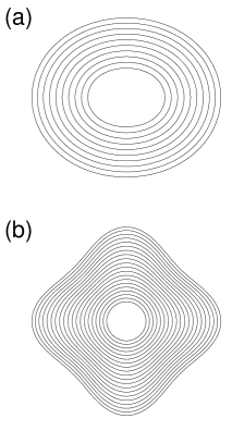
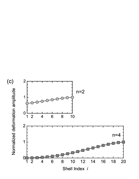
Figure 1 (a) and (b) illustrate elastic buckling modes of MWNTs with and under hydrostatic pressure, respectively; nm is fixed, and the mode index indicates the wave number of the deformation mode along the circumference. In the elliptic mode with shown in Fig. 1 (a), all concentric shells are almost uniformly deformed so that consecutive shells are equally spaced even after deformation. This behavior becomes more clear by plotting the normalized deformation amplitudes of individual concentric shells as given in the upper plot of Fig. 1 (c). By increasing , we obtain qualitatively different results as shown in Fig. 1(b), where the cross-section yields a corrugation mode of . In the latter mode, outside shells exhibit significant deformation, while the innermost shell maintains its cylindrical symmetry.
We point out that the persistence of cylindrical symmetry of the innermost shell will be useful in developing nanotube-based nanofluidic [21, 22, 23, 24] or nanoelectrochemical devices [26, 27], as both utilize the hollow cavity within the innermost shell. In fact, manifold class of intercalated molecules can fill the innermost hollow cavities of nanotubes [22, 37], which trigger intriguing behaviors distinct from those of the corresponding bulk systems [38, 39, 41]. In particular, the innermost shell of MWNTs in the radial corrugation mode serves as an ideal protective shield for the intercalates, since it maintains its cylindrical geometry even under high external pressure.
4 Inner-shell corrugation of embedded MWNTs
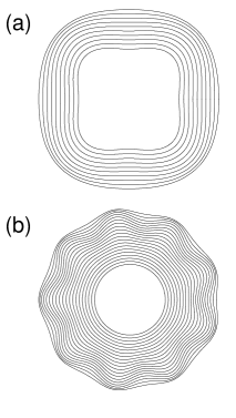
Figure 2 (a) and 2 (b) show two corrugation modes for MWNTs surrounded by an elastic medium with GPa and ; Figure 2 (c) indicates plots of relative deformation amplitude for the embedded case. From here we can see two characteristic tendencies which is not shown in the case of no elastic medium described in the previous section. First, corrugation mode exhibits in not only outside but also inside shells for a MWNT with . Second, the corrugation mode that remain its cylindrical symmetry is shown for , however, the deformation amplitude of the outermost shell is not always largest. This fact says that an embedded elastic medium may cause “inner tube instability”.

5 Concluding remarks
It has been found that in radial corrugation modes, large discrepancy in the deformation amplitudes between the outer and inner shells perturb the equal spacing between the concentric shells of the original MWNTs. In no embedded elastic medium cases, the cross-sectional shapes of inner shells maintain circle or oval. On the other hand, an embedded medium may cause inner shell corrugation modes especially when the number of shells for MWNTs is small. Such the modulation in inter-shell spacing will affect electronic and vibrational properties of the entire nanotube, thus triggering a change in its electronic and thermal conductance.
We also conjecture that those pressure-induced changes in physical properties of MWNTs are of practical use for developing MWNT-based pressure sensors. It is particularly hoped that our results should be verified by high-pressure experiments on MWNTs as well as atomic-scale large-scale simulations [42, 43, 44].
Before closing, it deserves comments on the relevance of our results to quantum transport of low-dimensional nanostructures. It is theoretically known [45] that quantum particles moving along a thin curved surface behave differently from those on a conventional flat plane, since nonzero geometric curvature results in an effective electromagnetic field [46, 47, 48, 49, 50]. In this context, quantum transport of electrons moving in MWNTs under pressure will exhibit non-trivial surface curvature effects, though details are to be explored. Intensive studies on the issues mentioned above will shed light on novel MWNT applications based on cross-sectional deformation.
Acknowledgements
We acknowledge Professor T. Mikami for stimulating discussions. This study was supported by a Grant-in-Aid for Scientific Research on Innovative Areas and the one for Young Scientists (B) from the MEXT, Japan. M.S and H.S are thankful for financial supports from Hokkaido Gas Co., Ltd. and Executive Office of Research Strategy in Hokkaido University. H.S is also grateful for the support from the Kajima Foundation. A part of the numerical simulations were carried out using the facilities of the Supercomputer Center, ISSP, University of Tokyo.
References
- [1] V. N. Popov, Mater. Sci. Eng. 43 (2004) 61.
- [2] M. Sato and H. Shima, Interact. Multi. Mech. 2 (2009) 209.
- [3] C. J. Park, Y. H. Kim, and K. J. Chang, Phys. Rev. B 60 (1999) 10656.
- [4] C. Gómez-Navarro, J. J. Sáenz, and J. Gómez-Herrero, Phys. Rev. Lett. 96 (2006) 076803.
- [5] J. Z. Cai, L. Lu, W. J. Kong, H. W. Zhu, C. Zhang, B. Q. Wei, D. H. Wu, and F. Liu, Phys. Rev. Lett. 97 (2006) 026402.
- [6] M. Monteverde, G. Garbarino, M. Núñez-Regueiro, J. Souletie, C. Acha, X. Jing, L. Lu, Z. W. Pan, S. S. Xie, and R. Egger, Phys. Rev. Lett. 97 (2006) 176401.
- [7] T. Nishio, Y. Miyato, K. Kobayashi, K. Matsushige, and H. Yamada, Appl. Phys. Lett. 92 (2008) 063117.
- [8] A. P. M. Barboza, A. P. Gomes, B. S. Archanjo, P. T. Araujo, A. Jorio, A. S. Ferlauto, M. S. C. Mazzoni, H. Chacham, and B. R. A. Neves, Phys. Rev. Lett. 100 (2008) 256804.
- [9] Y. Ren, K-Q. Chen, Q. Wan, B. S. Zou, and Y. Zhang, Appl. Phys. Lett. 94 (2009) 183506.
- [10] U. D. Venkateswaran, A. M. Rao, E. Richter, M. Menon, A. Rinzler, R. E. Smalley, and P. C. Eklund, Phys. Rev. B 59 (1999) 10928.
- [11] R. S. Deacon, K. C. Chuang, J. Doig, I. B. Mortimer, and R. J. Nicholas, Phys. Rev. B 74 (2006) 201402(R).
- [12] S. Lebedkin, K. Arnold, O. Kiowski, F. Hennrich, and M. M. Kappes, Phys. Rev. B 73 (2006) 094109.
- [13] M. J. Longhurst and N. Quirke, Phys. Rev. Lett. 98 (2007) 145503.
- [14] M. Yao, Z. Wang, B. Liu, Y. Zou, S. Yu, W. Lin, Y. Hou, S. Pan, M. Jin, B. Zou, T. Cui, G. Zou, and B. Sundqvist, Phys. Rev. B 78, 205411 (2008)
- [15] T. Chang, Appl. Phys. Lett. 93 (2008) 061901.
- [16] N. Sinha, J. Ma, J. T. W. Yeow, J. Nanosci. Nanotechnol. 6 (2006) 573.
- [17] T. Zhang, S. Mubeen, N. V. Myung, and M. A. Deshusses, Nanotechnology 19 (2008) 332001
- [18] C. Li, E. T. Thostenson, and T-W. Chou, Comp. Sci. Tech. 68 (2008) 1227.
- [19] J. Tang, J. C. Qin, T. Sasaki, M. Yudasaka, A. Matsushita, and S. Iijima, Phys. Rev. Lett. 85 (2000) 1887.
- [20] S. Zhang, R. Khare, T. Belytschko, K. J. Hsia, S. L. Mielke, and G. C. Schatz, Phys. Rev. B 73 (2006) 075423.
- [21] M. Majumder, N. Chopra, R. Andrews and B. J. Hinds, Nature (London) 438 (2005) 44.
- [22] A. Noy, H. G. Park, F. Fornasiero, J. K. Holt, C. P. Grigoropoulos and O. Bakajin, Nano Today 2 (2007) 22.
- [23] M. Whitby and N. Quirke, Nat. Nanotechnol. 2 (2007) 87.
- [24] N. Khosravian and H. Rafii-Tabar, Nanotechnology 19 (2008) 275703.
- [25] D. Mattia and Y. Gogotsi, Microfluid. Nanofluid. 5 (2008) 289
- [26] E. Frackowiak and F. Beguin, Carbon 40 (2002) 1775.
- [27] D. Tasis, N. Tagmatarchis, A. Bianco, and M. Prato, Chem. Rev. 106 (2006) 1105.
- [28] C. Q. Ru, Phys. Rev. B 62 (2000) 16962.
- [29] H. S. Shen, Int. J. Solids. Struct. 41 (2004) 2643.
- [30] X. Q. He, S. Kitipornchai, and K. M. Liew, J. Mech. Phys. Solids 53 (2005) 303.
- [31] H. Shima and M. Sato, Nanotechnology 19 (2008) 495705.
- [32] H. Shima and M. Sato, physica status solidi (a) (2009) in press (DOI:10.1002/pssa.200881706)
- [33] A. Sears and R. C. Batra, Phys. Rev. B 69 (2004) 235406.
- [34] Y. Huang, J. Wu, and K. C. Hwang, Phys. Rev. B 74 (2006) 245413.
- [35] J. Peng, J. Wu, K. C. Hwang, J. Song, and Y. Huang, J. Mech. Phys. Solid. 56 (2008) 2213.
- [36] W. B. Lu, B. Liu, J. Wu, J. Xiao, K. C. Hwang, S. Y. Fu, and Y. Huang, Appl. Phys. Lett. 94 (2009) 101917.
- [37] K. V. Shanavas and Surinder M. Sharma, Phys. Rev. B 79 (2009) 155425.
- [38] Monthioux M 2002 Carbon 40 1809
- [39] C. K. Yang, J. Zhao and J. P. Lu, Phys. Rev. Lett. 90 (2003) 257203.
- [40] H. Shima, M. Sato, and K. Iiboshi, unpublished.
- [41] S. Joseph and N. R. Aluru, Nano Lett. 8 (2008) 452.
- [42] I. Arias and M. Arroyo, Phys. Rev. Lett. 100 (2008) 085503.
- [43] M. Arroyo and I. Arias, J. Mech. Phys. Solids 56 (2008) 1224.
- [44] J. Zou, X. Huang, M. Arroyo, and S. L. Zhang, J. Appl. Phys. 105 (2009) 033516.
- [45] R. C. T. da Costa, Phys. Rev. A 23 (1981) 1982.
- [46] H. Shima, H. Yoshioka and J. Onoe, Phys. Rev. B 79 (2009) 201401.
- [47] H. Shima, H. Yoshioka and J. Onoe, submitted to Physica E.
- [48] S. Ono and H. Shima, Phys. Rev. B 79 (2009) 235407 (2009).
- [49] S. Ono and H. Shima, submitted to Physica E.
- [50] H. Taira and H. Shima, submitted to Phys. Rev. B [arXiv:0904.3149].