AFM Dissipation Topography of Soliton Superstructures in Adsorbed Overlayers
Abstract
In the atomic force microscope, the nanoscale force topography of even complex surface superstructures is extracted by the changing vibration frequency of a scanning tip. An alternative dissipation topography with similar or even better contrast has been demonstrated recently by mapping the -dependent tip damping: but the detailed damping mechanism is still unknown. Here we identify two different tip dissipation mechanisms: local mechanical softness, and hysteresis. Motivated by recent data, we describe both of them in a one-dimensional model of Moiré superstructures of incommensurate overlayers. Local softness at “soliton” defects yields a dissipation contrast that can be much larger than the corresponding density or corrugation contrast. At realistically low vibration frequencies, however, a much stronger and more effective dissipation is caused by the tip-induced nonlinear jumping of the soliton, naturally developing bi-stability and hysteresis. Signatures of this mechanism are proposed for experimental identification.
pacs:
46.55.+d, 07.79.Lh, 07.79.Sp, 81.40.Pq, 62.20.QpI Introduction
The tip-based scanning force microscopes of the atomic force microscope (AFM) family constitute perhaps the single most important tool bag in nanotechnology. The substrate topography is extracted from a map of the oscillation frequency of a tip, hovering a short distance above the surface. Besides the frequency shift however, the tip also develops a damping, reflecting a position dependent mechanical dissipation. Maier et al. Mai (a, b) showed recently that AFM dissipation – whose general occurrence has been widely discussed by several groups a decade ago Gau (a); Ben ; Lop (a, b); Hof (a) but whose potential importance was still underestimated – is able to map exquisitely delicate features such as the Moiré superstructure pattern formed by misfit dislocations (“solitons”) of incommensurate KBr adsorbate islands (Fig. 1a) on NaCl(100). Surprisingly, the experimental dissipation map, Fig. 1b, showed similar or better contrast than the corresponding topographic map, with a characteristic reversed contrast (higher dissipation at the soliton, where topographic height is minimal Bak ). Given also the great importance of achieving newer routes toward high-quality imaging, this is more than a mere curiosity, and deserves a proper understanding. Existing linear-response theory and other approaches to AFM dissipation Gau (b, a) and to general frictional dissipation Gra ; Per (a, b) suggest a larger tip damping above softer substrates, and that provides an initial and valuable clue. Local tip dissipation can effectively reveal the underlying superstructure, since the local mechanical compliance is higher for example at surface soliton lines, where atoms sit at metastable positions. However at the relatively low AFM oscillation frequencies, the current understanding rules out linear response as the chief dissipation mechanism. A typical energy dissipation as large as eV per oscillation can only be accounted for by a hysteretic response of the interacting tip-substrate system, as was understood by theoretical analysis Kan ; Tre ; Gha , and demonstrated experimentally Sch ; Hof (b). Such nonlinear effects of hysteresis are most likely involved in the surprisingly large AFM dissipation contrast of adsorbate superstructures too. Yet, it is unclear how inert systems (such as for example alkali halide overlayers) could give rise to hysteretic phenomena, and in particular how they would be connected to the presence of misfit superstructures (”solitons”) . This is the issue which we address here by means of dynamical simulations of the simplest one-dimensional model. Our main result is the identification of an unexpected soliton-related hysteretic mechanism. During the first part of its swing, the tip can locally drag or push an underlying defect – here a soliton portion – causing it to jump across a (Peierls-Nabarro) energy barrier. During the return journey, the defect follows only sluggishly, and remains trapped somewhat longer on the wrong side of the energy barrier, thus opening a hysteresis loop. The area enclosed in the hysteretic force-displacement diagram represents a large tip energy dissipation, one that can survive down to realistically low AFM vibration frequencies, a regime where the linear-response dissipation is quantitatively irrelevant. This mechanism is likely to play a significant role every time a “softness pattern” is present, and should be easier to observe for horizontal than for vertical tip oscillations.
(a) 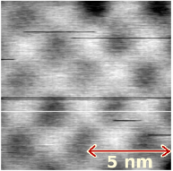 (b)
(b) 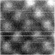
(c) 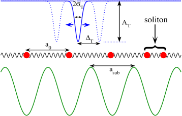
II The model
To emphasize the basic and general aspects of the phenomena, rather than a realistic model targeted on the chemical detail of a specific tip/sample configuration Kan ; Tre ; Gha ; Cac , we use the simplest possible model – a tip potential oscillating over a one-dimensional harmonic chain (the overlayer) moving in a rigid incommensurate periodic potential (the substrate), Fig. 1c. The Hamiltonian of the mobile overlayer atoms is
| (1) |
where is the kinetic energy,
| (2) |
is the mutual (harmonic) interaction potential, and is the substrate potential, which we take of a pure cosine form:
| (3) |
Here is the mean spacing between adatoms, is their mutual spring constant, , and is the period of the substrate potential Bra ; Van . The two periodicities and define the coverage . For convenience we take as the unit length, as the force unit, and the mass of the particles as the mass unit. (To get a feeling for quantities, the frequency units should be typical of an atomic vibration or a Debye frequency , typically 1 THz or more). The general lack of commensuration between adsorbate and substrate periodicities gives rise to two-dimensional misfit dislocations, sometimes called solitons, which form a regular superstructure with the beat periodicity between the two. Fixed boundary conditions (BCs) are chosen in order to prevent the advancing tip to drag the entire pattern along, that would occur if, e.g., periodic BCs were used instead.
is the time-dependent oscillating potential describing the tip action on the overlayer. We represent the AFM tip as a Gaussian-shaped oscillating potential, with , , and
| (4) |
Here represents the repulsive (contact AFM, ) or attractive (noncontact AFM, ) tip-atom interaction strength, is the tip width, and are the tip oscillation amplitude and angular frequency around its central position .
The equation of motion for the -th overlayer atom is
| (5) |
where , and the tip force
| (6) |
is given by a straightforward analytical expression. A damping force term is introduced to represent all dissipation phenomena which remove energy and allow the attainment of a stationary frictional state.
We integrate the equations of motion (5) by means of a standard adaptive fourth-order Runge-Kutta routine Num starting each simulation from a stationary fully relaxed overlayer, as obtained by a preliminary relaxation of equally-spaced adatoms and . All simulations are carried out at a nearly commensurate coverage , realized by means of a chain of particles in a region of length . A finite temperature is implemented by adding a standard Langevin random force to Eq. (5), and averaging over a long simulation time, usually at least 100 tip-oscillation periods. The extreme simplicity of the model allows us to extend simulations down to the realistic AFM frequency in the MHz range, which requires exceedingly long integration times.
The instantaneous power drained away by the damping term amounts to
| (7) |
and is thus proportional to the total kinetic energy of the overlayer. The power pumped by the tip into the chain is
| (8) |
While these two quantities fluctuate separately, they must of course coincide on average over a period in the dynamical steady state
| (9) |
also indicating how the work done by the tip oscillation is eventually dissipated entirely by the viscous friction term.
III Results: linear response and beyond
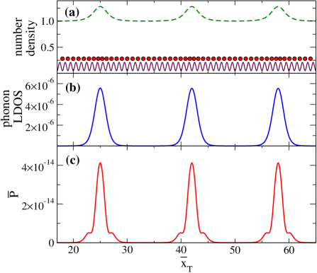
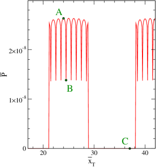
Figure 2 displays the dissipation results obtained in simulation for a weakly attractive tip potential, very high oscillation frequency, and general parameters that fall well inside the linear-response regime Gau (b, a); Gra ; Per (a, b). The linear response results show (i) strong dissipation enhancement at solitons, with several orders of magnitude stronger than in a terrace between two of them, closely mirroring the phonon local density of states (LDOS); (ii) dissipated power which is proportional to , independent of the attractive/repulsive sign of the tip-overlayer interaction, i.e. of the noncontact or contact mode of the AFM; (iii) absolute dissipation values that are very weak everywhere, and dropping with decreasing AFM frequency as . Summing up, the predicted relative contrast of the soliton pattern in linear response dissipation is indeed very large. However, the exceedingly low value of realistic AFM frequencies (MHz) relative to microscopic frequencies (THz) renders this linear-dissipation mechanism entirely academic.
a
 b
b
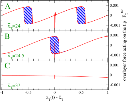
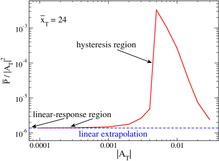
We reach a more realistic regime by enhancing the tip-overlayer interaction strength, while still remaining in a moderate-interaction regime representing noncontact AFM. This new regime is dominated by nonlinear effects, where dissipation no longer drops as , but at most linearly in (apart from logarithmic corrections). Comparison of Fig. 3a with Fig. 2c shows that, nonlinear dissipation is again much larger near the solitons than in between them. A two-order of magnitude increase in would in linear regime imply a dissipation increase by a factor , whereas we find a much larger factor of about already at this large frequency ( is here , corresponding to the gigahertz range). Decreasing frequency down to realistic AFM values, the increase will become gigantic, because the nonlinear dissipation lacks the extra power of appearing in the linear-regime dissipation. The new element brought in by nonlinearity is mechanical. A strongly interacting tip is now able to drag, or to push, the soliton – a mobile entity – forward or backward during the oscillation cycle. As the soliton must overcome the (Peierls-Nabarro) barrier in order to move, its motion is sluggish, and can follow the tip only with hysteresis and, as anticipated, hysteresis entails a large dissipation. As shown in detail in Fig. 3a,b, the higher dissipation point A is found to corresponds to two successive Peierls-Nabarro barriers being overcome in the oscillatory process, the smaller dissipation point B to a single barrier. The dissipation at point C, where the tip potential is unable to “grab” the soliton, is negligible by comparison. The onset of this large-dissipation region, dominated by hysteresis, is rather sharp. Fig. 4 illustrates this point, by showing the average power at location A, divided by the linear-regime factor , as a function of the tip amplitude . Beyond a value of of order , the linear regime behavior is abruptly abandoned, and the dissipation increases rapidly by several orders of magnitude.
IV Predictions and discussion
Our simulated example strongly suggests that a large hysteretic component should be present in the existing dissipation maps Alb of Moiré patterns. More generally, hysteretic defect dragging should dominate the AFM dissipation maps. What are the predicted signatures of this mechanism? Our model study suggests two main signatures.
(i) Abruptness of AFM friction onset with increasing strength of tip-surface interaction. As suggested by Figs. 3-4, dragging sets in abruptly only above a certain threshold, which means below a certain tip-surface or tip-soliton distance.
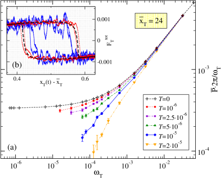
(ii) Anomalously mild (linear with logarithmic corrections) frequency dependence of AFM friction at finite temperature. It is a rather general property of all hysteretic friction phenomena to heal away at sufficiently low frequencies, where adiabatic motion allows sufficient time to jump thermally over barriers. For instance, thermolubricity experiments Gne (a); Rie ; Gne (b); Sil and detailed calculations within the Tomlison model San show an average friction force , where is the driving velocity, and and are system-dependent dimensional constants. In incommensurate overlayers, the soliton nearest to the tip behaves similarly to a Tomlinson particle, as is driven across a Peierls-Nabarro barrier. In Fig. 5a we do observe a thermal reduction of dissipation, due to a shrinkage of the hysteretic loop, illustrated in Fig. 5b. When driving is oscillatory as in AFM dissipation, the role of is taken by . We find our data to be compatible with a similar relation . The parameters and are here related to the effective soliton properties (mass, damping, barrier height…), and are nontrivial functions of the “bare” model parameters.
We conclude that AFM dissipation maps of incommensurate overlayer superstructures can in principle achieve an extremely high contrast resolution of soliton defects relative to commensurate terraces. The most important theoretically predicted dissipation mechanism is the nonlinear dragging or pushing of some local portion of the defect, where the large tip damping is associated with hysteresis of defect motion. Besides a sharp threshold in the tip-surface interaction and oscillation magnitudes, this mechanism predicts a very characteristic logarithmic dependence (eventually turning to linear at extremely low frequencies) of dissipation upon frequency and temperature. More generally, the nonlinear dragging of soft defects or features (e.g. a floppy residue in a biomolecule) should give rise to a strong visibility in AFM dissipation topography, of considerable potential impact for applications.
Acknowledgements.
This work was supported by CNR, as a part of the European Science Foundation EUROCORES Programme FANAS.References
- Mai (a) S. Maier, E. Gnecco, A. Baratoff, R. Bennewitz, and E. Meyer, Phys. Rev. B 78, 045432 (2008).
- Mai (b) S. Maier, O. Pfeiffer, Th. Glatzel, E. Meyer, T. Filleter, and R. Bennewitz, Phys. Rev. B 75, 195408 (2007).
- Gau (a) M. Gauthier and M. Tsukada, Phys. Rev. Lett. 85, 5348 (2000).
- (4) R. Bennewitz, A. S. Foster, L. N. Kantorovich, M. Bammerlin, C. Loppacher, S. Schär, M. Guggisberg, E. Meyer, and A. L. Shluger, Phys. Rev. B 62, 2074 (2000).
- Lop (a) C. Loppacher, R. Bennewitz, O. Pfeiffer, M. Guggisberg, M. Bammerlin, S. Schär, V. Barwich, A. Baratoff, and E. Meyer, Phys. Rev. B 62, 13674 (2000).
- Lop (b) C. Loppacher, M. Bammerlin, M. Guggisberg, S. Schär, R. Bennewitz, A. Baratoff, E. Meyer, and H.-J. Güntherodt, Phys. Rev. B 62, 16944 (2000).
- Hof (a) P. M. Hoffmann, S. Jeffery, J. B. Pethica, H. Özgür Özer, and A. Oral, Phys. Rev. Lett. 87, 265502 (2001).
- (8) J. Baker and P.-A. Lindgard, Phys. Rev. B 54, R11137 (1996).
- Gau (b) M. Gauthier and M. Tsukada, Phys. Rev. B 60, 11716 (1999).
- (10) E. Granato and S. C. Ying, Phys. Rev. B 59, 5154 (1999).
- Per (a) B. N. J. Persson, Sliding Friction: Physical Principles and Applications (NanoScience and Technology) (Springer-Verlag, Berlin 1998).
- Per (b) B. N. J. Persson, E. Tosatti, D. Fuhrmann, G. Witte, and Ch. Wöll, Phys. Rev. B 59, 11777 (1999).
- (13) L. N. Kantorovich and T. Trevethan, Phys. Rev. Lett. 93, 236102 (2004).
- (14) T. Trevethan and L. Kantorovich, Nanotechnology 17, S205 (2006).
- (15) S. A. Ghasemi, S. Goedecker, A. Baratoff, T. Lenosky, E. Meyer, and H. J. Hug, Phys. Rev. Lett. 100, 236106 (2008).
- (16) A. Schirmeisen and H. Hölscher, Phys. Rev. B 72, 045431 (2005).
- Hof (b) R. Hoffmann, A. Baratoff, H. J. Hug, H. R. Hidber, H v Löhneysen, and H.-J. Güntherodt, Nanotechnology 18, 395503 (2007).
- (18) V. Caciuc, H. Hölscher, D. Weiner, H. Fuchs, and A. Schirmeisen, Phys. Rev. B 77, 045411 (2008).
- (19) O. M. Braun and Yu. S. Kivshar, The Frenkel-Kontorova Model: Concepts, Methods, and Applications (Springer-Verlag, Berlin, 2004).
- (20) A. Vanossi and O. M. Braun, J. Phys.: Condens. Matter 19, 305017 (2007).
- (21) W. H. Press, S. A. Teukolsky, W. T. Vetterling and B. P. Flannery, Numerical Recipes in Fortran. The Art of Parallel Scientific Computing (Cambridge University Press, Cambridge, 1996).
- (22) B. J. Albers, T. C. Schwendemann, M. Z. Baykara, N. Pilet, M. Liebmann, E. I. Altman, and U. D. Schwarz, Nature Nanotech. 4, 307 (2009).
- Gne (a) E. Gnecco, R. Bennewitz, T. Gyalog, Ch. Loppacher, M. Bammerlin, E. Meyer, and H.-J. Güntherodt, Phys. Rev. Lett. 84, 1172 (2000).
- (24) E. Riedo, E. Gnecco, R. Bennewitz, E. Meyer, and H. Brune, Phys. Rev. Lett. 91, 084502 (2003).
- Gne (b) E. Gnecco, R. Bennewitz, A. Socoliuc, and E. Meyer, Wear 254, 859 (2003).
- (26) S. Sills and R. M. Overney, Phys. Rev. Lett. 91, 095501 (2003).
- (27) Y. Sang, M. Dubé, and M. Grant, Phys. Rev. Lett. 87, 174301 (2001).