Oscillating horizontal bar problem revisited
Abstract
A simple text book problem in mechanics[1], describes a massive horizontal bar placed on two oppositely rotating rollers, kept at a fixed center to center distance. Subsequent motion is to be found out in presence of kinetic frictions at the point of contacts of the two rollers[2]. Introducing bulk rolling friction effects, through the contact planes and considering viscoelastic rollers, we find that the inverse of the square of the oscillation frequency of the bar has a linear relationship with the center to center distance. The gradient and intercept of the linear relation together with observations about two consecutive positions of the bar, determine the rolling friction coefficient of the viscoelastic materials of the two rollers fully.
I Introduction
An interesting text book problem in the introductory mechanics([1]) is to determine the motion of a bar. The bar is uniform, hard, heavy and has weight W. It is placed horizontally on two hard rollers. Both the cylindrical rollers have got the same radius R. The rollers are mounted such that axes of the two are parallel. These are rotated with almost the same constant angular speed . The left roller is rotated clockwise. The right roller is made to revolve anticlockwise. The axes of rotation are L distance apart. The rollers are made of the same material. Surfaces are polished to the same degree. Kinetic friction coefficient is the same for both the rollers at the contact lines with the bar. Coefficient of kinetic friction, , is independent of the speeds of the bar and the rollers. The bar subsequently executes S.H.M.[2] with angular frequency . The result is noteworthy. Reciprocal of the square of the angular frequency is proportional to L. The proportionality constant, apart from 2g, is . In principle, one can convert this text book problem into a working principle of an experiment, where the distance parameter L can be varied with simultaneous measurement of oscillation frequency, leading to a determination of the coefficient of kinetic friction .
When the identical rollers are not hard, life tickles into. The contact lines become planes. Through these planes each roller transmit one additional couple in order to make the local section of the bar to rotate along with it. This local torque is proportional to the normal force at the junction concerned. The constant of proportionality is the coefficient of rolling friction. Unlike kinetic friction this depends on speeds of the rollers as well as of the bar. The bar now oscillates, but oscillates with a modified frequency. Reciprocal of the square of the angular frequency is linear in L, not proportional to L. The straight line representing the linear relation has got an intercept. The intercept is proportional to the rolling friction coefficient. This opens up better avenue. Convert the problem with soft rollers into the working principle of an experiment, where the distance L is varied with the measurement of oscillation frequency, leading to the simultaneous determination of the coefficients of rolling friction as well as kinetic friction.
In the section II, we work out the motion of hard bar on hard rollers. In the section III, hard bar on soft rollers are dealt with. In the following section IV, the ensuing experimental avenue is explored. At the end section V, we discuss about the window in which one has to restrict oneself, while designing a rolling friction experiment sophisticating this bar+roller setup.
II Rolling friction zero
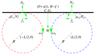
As the Fig.1 shows, five forces are acting on the bar. The normal force, , is acting through the contact lines and is perpendicular to the plane of the bar. The weight of the bar, , is passing through the center of gravity (C.G.) vertically downwards. The kinetic frictional forces, , are being exerted by the rollers below, through the lines of contact, along the directions of motion of the rollers. As the bar is uniform, the center of mass coincides with the the C.G. is the position of the center of gravity from the midpoint of the two rollers at an instant t. The bar is not translating in the vertical direction. Applying Newton’s law along the vertical direction one gets
| (1) |
The bar is not rotating about the center of gravity. Applying torque equation about an axis parallel to the axes of the rollers, at the C.G., one is led to
| (2) |
The net force on the bar along the horizontal direction is
| (3) |
provided one assumes that the kinetic friction coefficient, , is independent of the speed of the bar and the rollers.
Application of the Newton’s equation in the horizontal direction together with eqns.(1, 2, 3) leads one to the differential equation of motion,
| (4) |
The eq.4 implies that the bar executes simple harmonic motion with all allowable amplitude and phase ,
| (5) |
Angular frequency, , is given by
| (6) |
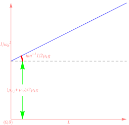
One notices that the angular frequency, , does not depend on the mass of the bar. It just depends on the characteristics of the two roller system. Moreover, as one varies the separation, , of the two roller system and plot the resulting against , as in the Fig.2, overlooking the intercept, the slope gives . is the kinetic friction coefficient. This might already be an working principle for the coefficient of kinetic friction measurement.
III Rolling friction non-zero
Rolling friction is predominantly a bulk effect[3]. It is due to hysteresis loss during repeated cycles of deformation and recovery of the body undergoing rolling. Rolling friction mainly depends upon four parameters. These are mechanical properties of the body, radius of the rolling object, softness or, hardness of the body, bar here, in contact and the forward speed respectively. Mechanical properties involved are elastic constants and viscosity coefficients.
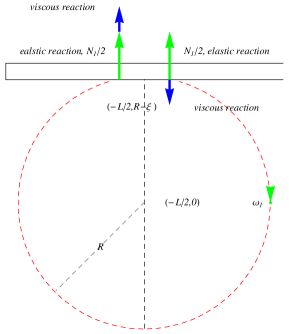
However, effects of rolling friction here is to introduce as shown in the Fig.1. These couple originate, as shown in the Fig.3 for the left roller, from the pair of viscous reaction forces. These viscous reaction couples on the bar originate as reactions to the couple of dissipative forces acting, from within, on the rollers, as these are pressed by the bar from the above.
As a result, the equation of torque about C.G.(2), changes to,
| (7) |
where, is the rolling frictional torque acting at the contact planes. Since, the bar is not translating in the vertical direction, the equation for the net force,(1), remains the same. Application of the Newton’s equation in the horizontal direction together with eqns.(1, 7, 3) now leads one to the differential equation of motion,
| (8) |
Hence, the bar executes simple harmonic motion with all allowable amplitude and phase ,
| (9) |
with modified angular frequency, ,
| (10) |
Ideally, . Practical limitations may not allow one to achieve the same angular speed for the two rollers, leaving unattainable.
IV Experimental Avenue
We cast the eq.10, in the more revealing form,
| (11) |
As shown in the Fig.2, the intercept is
| (12) |
Moreover, one notices that the equation of motion for the bar leads to
| (13) |
Combination of the two equations (12, 13) gives , separately.
Again,
| (14) |
and are the radius and angular speed of the roller concerned. This leads us to , velocity independent part of the velocity dependent[3, 4] rolling friction coefficient for the roller material. This works as long as the speed of sound in the roller with dissipative relaxation time of the rollers.
V Discussion
Differences in dip, , as in Fig.1 of right and left rollers, due to the difference, , leads to changes in the torque and force equations of the order of . Radius of the rollers being much larger, this contribution is neglected. Ideally the experiment should be done in the small and smaller angular velocity range of the roller and the bar[5] so that constancy of the kinetic friction is maintained. The linear relation for the rolling friction coefficient(14) is to be replaced by an appropriate non-linear relation[6, 7] when the roller speeds are higher. Here, we have ignored rolling friction effect due to surface. See the discussion in second page of the reference[3]. One can remove little air drag on the motion of the massive bar by putting the setup in a vacuum chamber. Finally its nice to notice that such a simple text book problem leads to an interesting avenue into the experiment of rolling friction for viscoelastic material. Practical realisation of this avenue remains something to be done next.
References
- [1] D. Kleppner and R. J. Kolenkow, An Introduction to Mechanics(Tata McGraw-Hill, 1999), Prob. 6.9.
- [2] http://demonstrations.wolfram.com/ A Massive Bar Oscillating between Two Identical Rotating Support Roll/
- [3] N. V. Brilliantov and T. Poschel, ” Rolling friction of a viscous sphere on a hard plane”, Europhys. Lett.42, 511-16(1998)
- [4] N. V. Brilliantov, F. Spahn, J. M. Hertzsch, T. Poschel, ”Model for collision in granular gases”, Phys. Rev. E53, 5382-92(1996)
- [5] T. Poschel and H. J. Herrmann, ”A Simple Geometrical Model For Solid Friction”, cond-mat/93066062
- [6] Y. Xu and K. L. Yung, ” The effect of inertial normal force on the rolling friction of a soft sphere on a hard plane”, Europhys. Lett.61, 620-24(2003)
- [7] Y. Xu and K. L. Yung, ” Non-Linear Expressions for Rolling Friction of a Soft Ball on a Hard plane”, Nonlinear Dynamics 33, 33-41(2003).
email:anindya@bits-goa.ac.in