Plasmon polaritons in photonic superlattices containing a left-handed material
Abstract
We analyze one-dimensional photonic superlattices which alternate layers of air and a left-handed material. We assume Drude-type dispersive responses for the dielectric permittivity and magnetic permeability of the left-handed material. Maxwell’s equations and the transfer-matrix technique are used to derive the dispersion relation for the propagation of obliquely incident optical fields. The photonic dispersion indicates that the growth-direction component of the electric (or magnetic) field leads to the propagation of electric (or magnetic) plasmon polaritons, for either TE or TM configurations. Furthermore, we show that if the plasma frequency is chosen within the photonic zeroth-order bandgap, the coupling of light with plasmons weakens considerably. As light propagation is forbidden in that particular frequency region, the plasmon-polariton mode reduces to a pure plasmon mode.
Keywords: photonics, superlattices, plasmon polaritons
pacs:
PACS: 41.20.Jb, 42.70.Gi, 42.70.Qs, and 78.20.BhOver the years, artificial complex materials have been increasingly used to shape and manipulate light Shelby01 ; Barnes03 ; Maier05 ; Rama05 ; Ozbay06 . The microstructuring of high quality optical materials yields remarkable flexibility in the fabrication of nanostructures, and allows for the tailoring of electromagnetic dispersions and mode structures to suit almost any need. Metamaterials Dolling ; Zhu ; Dragoman ; Pacheco2002 ; Elef2002 ; Grbic2002 ; Li2003 ; Jiang2003 , also known as left-handed materials (LHMs), are a remarkable example of such nanostructuring. Light propagation through metamaterials is characterized by a phase velocity opposite to the Poyinting vector, which corresponds to negative dispersive electric and magnetic responses.
The advent of metamaterials has opened a new era for optical devices, and has also given considerable thrust to the recent area of plasmonics, the study of plasmon polaritons. In metal-dielectric interfaces, for example, surface-plasmon polaritons are coupled modes that result from resonant interactions between electromagnetic waves and mobile electrons at the surface of a metal or semiconductor. Such resonant surface-plasmon polaritons may have much shorter wavelengths than that of the radiation, which enables them to propagate along nanoscale systems Shelby01 ; Barnes03 ; Maier05 ; Rama05 , opening up a wide range of possibilities for the construction of new optical devices. It is well known, for example, that one of the most important features of surface-plasmon polaritons is to confine light to very small dimensions, yielding the merging of photonics and electronics at the nanoscale. Furthermore, considering the dispersive character of the LHM’s, together with the enhanced optical magnetism exhibited by them, one might conjecture the existence of remarkable new phenomena such as the excitation of plasmon polaritons of a magnetic nature, that is, magnetic density waves resulting from resonant interactions between the optical field and current densities at the metamaterial. Ultimately, those developments could lead to increases in the resolution of microscopes, in the efficiency of LEDs, and in the sensitivity of chemical and biological devices Ozbay06 ; Dolling ; Zhu ; Dragoman .
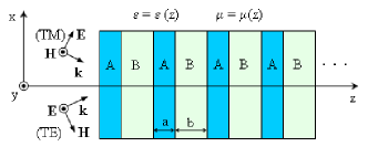
One-dimensional (1D) superlattices which alternate layers of positive and negative materials have already exhibited many interesting properties Smith00 ; Lisci06 ; Cavalcanti ; Shadrivov03 ; Zio04 ; Daninthe06 ; Yuan06 ; Euden07 ; Weng07 ; Zhang07 that are absent in superlattices composed solely of positive materials. In particular, the existence of a non-Bragg photonic bandgap, also known as a zeroth order gap, has been suggested Li2003 , detected Jiang2003 ; Smith00 , and characterized Lisci06 ; Cavalcanti . In order to investigate the possibility of excitation of electric/magnetic plasmon polaritons, in the present work we study the oblique incidence of light on a model 1D superlattice composed of layers A of air, and layers B of a doubly negative material. Layers A (width ) and B (width ) are distributed periodically so that is the period of the superlattice nanostructure (cf. Fig. 1).
In the B layers, the electric and magnetic responses are dispersive and may assume negative values. If one neglects losses, they may be described by Pacheco2002 ; Elef2002 ; Grbic2002 ; Li2003 ; Jiang2003
| (1) |
where and are the dielectric permittivity and magnetic permeability in slab B, respectively, one may choose Elef2002 ; Grbic2002 and , and the electric/magnetic plasmon modes are at and , which correspond to the solutions of and , respectively.
We note that dispersions such as those in (1) hold in periodically LC loaded transmission lines Elef2002 . These negative-index systems were shown to exhibit good microwave properties, with low loss and broad bandwidth Grbic2002 .
We shall be interested in studying the properties of both the transverse-electric (TE: electric field parallel to the interface plane, see Fig. 1) and transverse-magnetic (TM: magnetic field parallel to the interface) polarizations of a monochromatic electromagnetic field of frequency propagating through a 1D periodic system.
In the case of a TE field, one may choose
| (2) |
whereas, in the case of TM polarization, the magnetic field may be considered as
| (3) |
where we have assumed that the superlattice was grown along the axis, is the wavevector component along the direction, and is the cartesian unitary vector along the direction.
Maxwell’s equations lead to the following differential equations for the electric and magnetic amplitudes
| (4) |
and
| (5) |
where is the -position dependent refraction index.
In the sequel, and are the refraction indices, while and are the magnetic permeabilities in layers A and B, respectively. Note that, because of (1), the refraction index in layer B is a function of the frequency, and may be a real positive, real negative or a pure imaginary number. Also, note that , the incident wavevector component along the direction, may be obtained as a function of the angle of incidence by .
Equations (4) and (5) may be solved by means of the transfer-matrix technique (see, for example, the work by Cavalcanti et al Cavalcanti and references therein). For a real number, and , the procedure yields the TE polarization dispersion relation from the solution of the transcendental equation
| (6) | |||||
In the formula, is the Bloch wavevector along the direction which is the axis of the photonic crystal; fields in consecutive unit cells are related by the Bloch condition, i.e., by the phase factor . and are defined as
| (7) |
and
| (8) |
where, , and, in the last equality, we have made use of Snell’s law .
For a real number, and , the procedure yields the TE polarization dispersion relation from the solution of the transcendental equation
| (9) | |||||
where is still given by (7), but
| (10) |
Moreover, if , (9) is still valid, with still given by (7), but
| (11) |
where is the imaginary part of .
For the TM polarization, the transcendental equations (6) and (9), as well as the definitions of and for the different cases are also valid, provided one replaces by and by , where and are the dielectric permissivities in layers A and B, respectively.
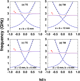
Figure 2 shows the calculated dispersions () in the cases of TE [Figs. 2(a) and 2(c)] and TM [Figs. 2(b) and 2(d)] polarizations, for different layer widths. Note that and fall outside the zeroth order bandgap. For (dashed curves), the second photonic band, just above the zeroth order gap, is a pure photonic mode and, for , there is a coupling between the radiation field and a plasmon mode which leads to a pair of plasmon-polariton modes. In other words, while for normal incidence the band just above the zeroth order gap is a pure photonic mode, for oblique incidence () the electromagnetic field + plasmon interaction leads to a pair of coupled modes. We emphasize that, for , the electric- and magnetic-field components along the growth direction are null and there is no longitudinal wave propagation. On the other hand, for , in the case of the TM (TE) configuration, the electric (magnetic) field has a component on the direction, which results in the excitation of longitudinal electric (magnetic) waves. For , Figure 2 illustrates that the pair of plasmon-polariton bands are asymptotic to the and pure electric/magnetic plasmon values. It is clear from Fig. 2 (a), for example, that at small values of , the lowest plasmon-polariton mode behaves like an electromagnetic photonic wave. As increases, the dispersion bends over and reaches the limiting value of the pure magnetic plasmon. On the other hand, the second plasmon-polariton branch behaves like a magnetic plasmon wave, at small , and like an electromagnetic photonic mode as increases. The same comments are valid for the other panels in Fig. 2 [of course, in the cases of Figs. 2(b) and 2(d), the electric plasmon mode is the one involved]. By comparing the results for normal and oblique incidence, it is clear that, for , resonant plasmon-polariton waves are excited by the coupling of the electric (or magnetic) plasmon modes with the incident eletromagnetic field. One may infer that the plasmon-polariton waves are excited by the magnetic field, in the TE case, or driven by the electric field, in the TM case. This is consistent with the fact that those longitudinal waves, in the TE case, are asymptotic to the pure magnetic plasmon frequency whereas, in the TM case, the plasmon-polariton bands are asymptotic to the pure electric plasmon mode.
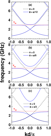
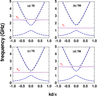
The calculated dispersions, for TE modes, as a function of the incidence angles are displayed in Fig. 3. We notice that the essential features persist irrespective of the incidence angle, although the Bragg gaps widens considerably for higher incidence angles. Also, Fig. 4 clearly indicates that, by choosing the resonant plasmon frequency within the zeroth order bandgap, the coupling of light to plasmon modes, for , essentially disappears leading to a basically pure (electric or magnetic) plasmon mode. This is a consequence of the fact that the energy of the incident electromagnetic wave lies in a forbidden energy gap region and, therefore, the coupling of the incident light with plasmons is expected to be quite weak.
Summing up, we have studied light propagation through a 1D superlattice composed of alternate layers of a positive constant material and a negative dispersive material, and verified the appearance of coupled plasmon-polariton modes of electric and magnetic natures. The photonic dispersion was calculated from Maxwell’s equations using the transfer-matrix approach, with the LHM modeled by Drude-like dielectric and magnetic responses. In the case of oblique incidence, the photonic dispersion indicates that the magnetic or electric field in the frequency region around the zeroth order bandgap leads to coupled magnetic or electric plasmon-polariton modes for the TE and TM configurations, respectively. Moreover, present results show that the coupling of light with plasmons is weakened by choosing the plasma frequency inside the zeroth order gap. As light propagation is forbidden in that particular gap-frequency region, the coupled plasmon-polariton mode becomes essentially a pure plasmon mode. This feature permits one to select which type of plasmon polariton (i.e., electric or magnetic) one is willing to excite, by choosing the magnetic or electric plasmon frequency within the zeroth order gap. Here, one might conjecture that the possibility of excitation of magnetic plasmon polaritons might provide a new avenue to the implementation of novel techniques and devices based on the interplay of photonics and magnetism at the nanoscale, similarly to the interplay of photonics and electronics. Therefore, the implementation of plasmonic chips for high data rate processing or efficient sensing applications might also be obtained based on the excitation of magnetic plasmon polaritons. Finally, we have studied an ideal system in which losses have been neglected, and future work including such effects is certainly forthcoming.
Acknowledgements.
We are grateful to the Brazilian Agencies CNPq, FAPESP, FAPERJ, and FUJB, the Colombian Agency COLCIENCIAS, and CODI - Univ. of Antioquia for partial financial support.References
- (1) R. A. Shelby, D. R. Smith, and S. Schultz, Science 292, 77 (2001).
- (2) W. L. Barnes, A. Dereux and T. W. Ebbesen, Nature 424, 824 (2003).
- (3) S. A Maier and H. A. Atwater, J. Appl. Phys. 98, 011101 (2005).
- (4) A. Ramakrishna, Rep. Prog. Phys. 68, 449 (2005).
- (5) E. Ozbay, Science 311, 189 (2006).
- (6) G. Dolling, C. Enkrich, M. Wegener, C. M. Soukoulis, and S. Linden, Opt. Lett. 31, 1800 (2006).
- (7) T. Li, J.-Q. Li, F.-M. Wang, Q.-J. Wang, H. Liu, S.-N. Zhuy and Y.-Y. Zhu, Appl. Phys. Lett. 90, 251112 (2007).
- (8) M. Dragoman and D. Dragoman, Prog. Quant. Electr. 32, 1 (2008).
- (9) J. Pacheco, Jr., T. M. Grzegorczyk, B.-I. Wu, Y. Zhang, and J. A. Kong, Phys. Rev. Lett. 89, 257402 (2002).
- (10) G. V. Eleftheriades, A. K. Iyer, and P. C. Kremer, IEEE Trans. Microwave Theory Tech. 50, 2702 (2002).
- (11) A. Grbic and G. V. Eleftheriades, J. Appl. Phys. 92, 5930 (2002); L. Liu, C. Caloz, C. C. Chang, and T. Itoh, J. Appl. Phys. 92, 5560 (2002).
- (12) J. Li, L. Zhou, C. T. Chan, and P. Sheng, Phys. Rev. Lett. 90, 083901 (2003).
- (13) H. Jiang, H. Chen, H. Li, Y. Zhang, and S. Zhu, Appl. Phys. Lett. 83, 5386 (2003).
- (14) D. R. Smith, W. J. Padilla, D. C. Vier, S. C. Nemat-Nasser, and S. Schultz, Phys. Rev. Lett. 84, 4184 (2000).
- (15) M. Liscidini and L. C. Andreani, Phys. Rev. E 73, 016613 (2006).
- (16) S. B. Cavalcanti, M. Dios-Leyva, E. Reyes-Gómez, and L. E. Oliveira, Phys. Rev. B 74, 153102 (2006); ibid., Phys. Rev. E 75, 026607 (2007); A. Bruno-Alfonso, E. Reyes-Gómez, S. B. Cavalcanti, and L. E. Oliveira, Phys. Rev. A 78, 035801 (2008).
- (17) I. V. Shadrivov, A. A. Sukhorukov, and Y. S. Kivshar, Appl. Phys. Lett. 82, 3820 (2003).
- (18) R. W. Ziolkowski, Phys. Rev. E 70, 046608 (2004).
- (19) H. Daninthe, S. Foteinopoulou, and C. M. Soukoulis, Photonics and Nanostruct. Fundam. Appl. 4, 123 (2006).
- (20) Y. Yuan, L. Ran, J. Huangfu, H. Chen, l. Shen, and J. A. Kong, Opt. Express 14, 2220 (2006).
- (21) M. S. Vasconcelos, P. W. Mauris, F. F. de Medeiros, and E. L. Albuquerque, Phys. Rev. B 76, 165117 (2007).
- (22) Y. Weng, Z-G. Wang, and H. Chen, Phys. Rev. E 75, 046601 (2007).
- (23) L. Zhang, Y. Zhang, L. He, Z. Wang, H. Li, and H. Chen, J. Phys. D: Appl. Phys. 40, 2579 (2007).