Spherical neutron polarimetry study of hysteresis in multiferroic MnWO4
Abstract
The electric-field dependence of the magnetic structure of multiferroic MnWO4 has been investigated using spherical neutron polarimetry as a function of temperature. The application of an electric field drives the magnetic structure to a single ‘chiral’ domain. The magnitude of the field required to do this is shown to increase with temperature. The link between the magnetic order and electric polarization is further demonstrated.
1 Introduction
The magneto-electric effect, whereby the application of a magnetic field induces electric polarization and the application of an electric field induces magnetization, has generated enormous interest lately due to its many possible applications [1, 2]. The recent revival is partly due to the identification of materials that become ferroelectric and ferromagnetic simultaneously. The frustrated, cycloidal, magnetic structure of these strongly coupled magneto-electrics gives rise to inverse Dzyaloshinsky-Moriya (DM) interactions [3, 4, 5], which, in turn, gives rise to an incommensurate modulation of the atomic structure with a propagation vector that is twice that of the magnetic propagation vector =2 [6]. The ferroelectric polarization is proportional to the phase difference, , between the chains of magnetically ordered ions where and are the magnitudes of the moments in the orthogonal directions and [7, 8]. The coupling shows great sensitivity to applied magnetic fields and, as we demonstrate in MnWO4, to the application of an electric field [9, 10]. Furthermore, the magnitude of the electric field that was required to effect a change in the magnetic order is shown to be highly sensitive to the temperature.
MnWO4 belongs to the family of multiferroic materials [9, 12, 13] with a frustrated, cycloidal magnetic order in the multiferroic phase. MnWO4 crystallizes in the wolframite structure with alternate layers of manganese and tungsten perpendicular to the axis. The structure is best described by the monoclinic space group, with and lattice parameters Å, Å and Å. The manganese is located at the 2 site and forms zig-zag chains of Mn2+ ions surrounded by edge sharing oxygen octahedra. MnWO4 has been shown to undergo three successive antiferromagnetic phase transitions that generate long wavelength magnetic structures [14, 15]. The first magnetically ordered state, AF3, occurs below = 13.5 K and is sinusoidally modulated with the easy direction in the plane forming an angle of to the axis. The second order transition to the AF2 phase at K introduces a component in the [010] direction that gives rise to the cycloidal magnetic order, with incommensurate (ICM) propagation vector = (-0.214, 0.5, 0.457). The final, first order, transition into the commensurate (CM) AF1 phase occurs at K and the structure becomes sinusoidally modulated once more with propagation vector = ( , , ) [14]. The AF2 phase has been demonstrated to be multiferroic, with the along with the axis, perpendicular to the easy plane [13] .
The magnetic structure was determined using spherical neutron polarimetry (SNP), the technique that gives the most accurate measurement of the ‘chiral’ terms of the magnetic tensor to give an insight into the phase and chirality of magnetic structures.[11].
2 Spherical Neutron Polarimetry
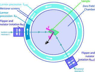
The SNP technique allows the polarized moments of the neutron beam to be arbitrarily oriented using a combination of two rotations corresponding to the spherical coordinate system [16, 17]. All components of the polarization matrix, with polarization axes defined with parallel to the scattering vector , with the zone axis of the crystal and completing the right handed cartesian set, are recorded, figure 1. The polarization matrix is the experimental quantity that is most closely related to the polarization tensor form of the Blume Maleev equations, fully described in [18, 19]. The perpendicular sine and cosine components of the cycloidal magnetic structure, when they lie perpendicular to the , give rise to a non-zero ‘chiral term’ as polarization is generated in the direction, described by the cross product term in the Blume Maleev equations, . An idealized experimental arrangement, which would have both components perpendicular to , is shown in figure 2. In this instance the polarization tensor will have the simplified form:
| (1) |
With the terms,
| (2) |
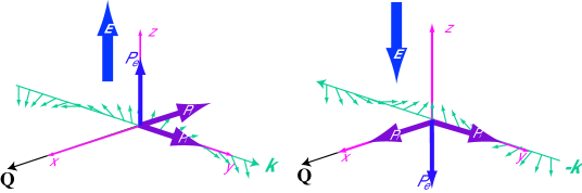
The component of the matrix gives the ellipticity of the cycloid, it is unity when the structure is spherical and the sine and cosine components have equivalent magnitudes. The component is the chiral term of the matrix, the magnitude is dependent on the population of each of the ‘chiral’ domains, ; when are equally populated =0; when the magnetism is ordered as a single domain will have a magnitude of one, with the sign of dependent on the handedness of , shown in figure 2.
As stated previously this is an idealised experimental arrangement, however, the matrix element is always non-zero when there is a real and imaginary part of the magnetic interaction vector perpendicular to .
3 Results and Discussion
The polarization matrix was measured using CRYOPAD on D3 at the ILL. The crystal was oriented with the [111] direction as the zone axis, along the direction. The polarization of the reflection - was measured to follow the changes in the component. The electric field was applied along the axis of the single crystal via sputtered gold contacts [20]. The field was ramped from 0Vmm-1 to 180Vmm-1 to 0Vmm-1 with constant temperature and then the polarity of the field was reversed and the process repeated. The crystals were cooled to the constant temperatures, 12K, 11K and 10K with a poling electric field applied.
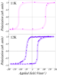
The coercive field at 12K is 50Vmm-1 a reduction in temperature by 1K to 11K increased the coercive field to 100Vmm-1. At 10K the coercive field could not be achieved with 180Vmm-1, but a reduction in the spin polarization was observed, an indication that at 200Vmm-1 the sign of would be inverted. The complete hysteresis loops recorded can be seen in figure 3.
The experiment was repeated at 13K in the higher temperature, ICM phase AF3 and at 6K in the lower temperature CM AF1 phase. There was no significant contribution to the ‘chiral’ terms of the polarization matrix at either of these temperatures and no hysteresis was recorded.
Overall, the sensitivity of the coercive field to the temperature is surprisingly large, approximately doubling as the temperature is reduced by 1K. The point at which the ‘chiral’ term becomes zero implies the domains are indistinguishable. The coercive field can be considered to be the field which is required to drive one of the chiral domains to have the same population equally populated, the and the domains are equivalent. This interpretation leads to the canceling of one of the components and the loops may be understood as the inter-conversion of the and the domains. This is possible as a cycloidal structure is not truly chiral, a rotation about the axis of followed by a phase shift of along will generate the oppositely ‘handed’ domain. Thus, the coercive field can be considered as the point at which the rotation about occurs, and the saturation as where the spin chain translates to optimize .
4 Conclusion
MnWO4 shows the spin polarization indicative of a magnetic structure with perpendicular sine and cosine components. The magnetic domain population has been controlled by the application of an electric field showing the link between magnetism and ferroelectricity, with a large sensitivity to temperature, in the multiferroic phase. The electric field had no influence on the magnetic structures in the AF3 or the AF1 phases showing that there is no magneto-electric coupling.
5 Acknowledgments
AP would like to thank the EPSRC (grant number EP/D053560) for financial support and A. T. Boothroyd and D. Prabhakaran for supplying the sample and Z. Davies for useful discussions.
References
References
- [1] Hill N A 2000 J. Phys. Chem. B 6694
- [2] Eerenstein W, Mathur N D and Scott J F 2006 Nature 759
- [3] Moriya T 1960 Phys. Rev. 91
- [4] Dzyaloshinsky I 1957 J. Phys. Chem. Solids 241
- [5] Sergienko I A and Dagotto E 2006 Phys. Rev. B 094434
- [6] Taniguchi K, Abe N, Sagayama H et al 2008 Phys. Rev. B 64408
- [7] Davies Z, Poole A and Wills A S unpublished work
- [8] Mostovoy M 2006 Phys. Rev. Lett. 067601
- [9] Taniguchi K, Abe N, Ohtani S et al 2006 Phys. Rev. Lett. 097203
- [10] Yamasaki Y, Sagayama H, Goto T et al 2008 Phys. Rev. Lett. 219902
- [11] Brown P J, Forsyth J B and Tasset F 2005 Solid State Science 682
- [12] Heyer O, Hollmann N, Klassen I et al 2006 J. Phys.: Condens. Matter L471
- [13] Arkenbout A H, Palstra T T M, Siegrist T and Kimura T 2006 Phys. Rev. B 184431
- [14] Lautenschläger G, Weitzel H, Vogt T et al 1993 Phys. Rev. B 6087
- [15] Ehrenberg H, Weitzel H, Heid C et al 1997 J. Phys.: Condens. Matter 3189
- [16] Lelièvre-Berna E, Bourgeat-Lami E, Fouilloux P, et al 2005 Physica B 131
- [17] Poole A, Wills A S and Lelièvre-Berna E 2007 J. Phys.: Condens. Matter 452201
- [18] Blume M 1963 Phys. Rev. 1670
- [19] Brown P J, Forsyth J B and Tasset F 1993 Proc. R. Soc. Lond. A 147
- [20] Poole A, Wills A S, Boothroyd A et al unpublished work