Versatile transporter apparatus for experiments with optically trapped Bose-Einstein condensates
Abstract
We describe a versatile and simple scheme for producing magnetically and optically-trapped 87Rb Bose-Einstein condensates, based on a moving-coil transporter apparatus. The apparatus features a TOP trap that incorporates the movable quadrupole coils used for magneto-optical trapping and long-distance magnetic transport of atomic clouds. As a stand-alone device, this trap allows for the stable production of condensates containing up to one million atoms. In combination with an optical dipole trap, the TOP trap acts as a funnel for efficient loading, after which the quadrupole coils can be retracted, thereby maximizing optical access. The robustness of this scheme is illustrated by realizing the superfluid-to-Mott insulator transition in a three-dimensional optical lattice.
pacs:
67.85.-d, 37.10.Gh, 67.85.Hj1 Introduction
Techniques for the optical trapping and manipulation of Bose-Einstein condensates have enabled experiments on a broad range of topics including Feshbach resonances [1], spinor condensates [2], and many-body effects in optical lattices [3]. Moreover, all-optical schemes [4] have eliminated the need for magnetic trapping in evaporative cooling applications. Nevertheless, the use of magnetic traps remains attractive due to their large volume, depth and passive stability. Major recent developments include the advent of miniaturized chip-based magnetic traps [5] and the realization of transporter apparatus designs [6, 7, 8, 9] in which the main chamber used for laser cooling is spatially separated from the science cell in which experiments with the condensate are performed.
Two generic types of transporter apparatus can be distinguished. In one type, an evaporatively cooled cloud in or near the quantum degenerate regime is first produced in the main chamber and subsequently delivered into the science cell using an optical tweezer [8, 9]. In the second type, a laser-cooled, magnetically trapped cloud is first moved into the science cell, before evaporation is performed. Here, the transport is achieved by either using a chain of overlapping stationary coil pairs [6], or by mechanically displacing a single, movable pair of coils [7]. Transporter machines have become increasingly popular, and both the optical and magnetic types are now in use by a number of groups.
In comparing the two apparatus types, a certain complementarity can be noticed. The optical tweezer design allows for nearly unobstructed optical access in the science cell, but it requires the ability to perform evaporative cooling already in the main chamber, thus imposing stringent conditions on the vacuum and complicating apparatus design. In contrast, magnetic transporters only require a simple vapor cell for laser cooling, but the presence of a permanent magnetic coil assembly for evaporation restricts optical access in the science cell.
In this paper, we present a novel implementation of a magnetic-coil transporter apparatus, based on moving coils, that shares the advantages of the optical tweezer scheme and also minimizes the overall design complexity: by adding a homogeneous rotating bias field to that of the movable coil pair, a stable trap of the TOP type [10], well-suited for condensate production, is formed in the science cell. Since the same quadrupole coil pair is used for magneto-optical trapping, transport, and evaporation, the TOP trap can thus be operated as a “retractable funnel” to load an optical trap, resulting in almost unobstructed optical access.
Hybrid traps, realized by the addition of either a blue [11, 12] or red [13] detuned laser beam to the quadrupole potential, could present an alternative to the solution presented here in the context of a moving-coil magnetic transporter. However, retaining the ability to produce condensates in an alignment-free configuration seems advantageous for stable day-to-day operation. Also, we are able to efficiently load condensates into optical traps without incurring the need for high beam intensities.
This paper is organized as follows: Section II gives an overview of the experimental setup, before the general features and technical implementation of the TOP trap are discussed in section III. Section IV characterizes the performance of the trap for condensate production, and section V illustrates its use in conjunction with optical trapping applications.
2 Overview of experimental setup
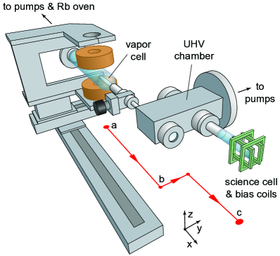
Our moving-coil transporter apparatus is illustrated in figure 1. A cylindrical glass vapor cell is connected to a UHV chamber with an attached small quartz glass science cell (cf. also figure 2) through a differential pumping tube. In the vapor cell, we collect up to atoms in a standard six-beam 87Rb MOT, making use of light induced atom desorption (LIAD) [14, 15, 16] to temporarily enhance the loading rate. After an 8 ms molasses phase that lowers the temperature to about 25 K, the atoms are optically pumped to the hyperfine ground state, and subsequently caught in a magnetic quadrupole trap using the same coil pair as for the MOT at an axial field gradient of 100 G/cm, yielding trapped atoms at 150 K.
The quadrupole coils are mounted on a mechanical translation stage assembly, which is used to move the magnetically trapped cloud into the science cell. This is done as quickly as possible ( m/s2, m/s) in order to minimize losses due to collisions with background gas atoms in the vapor cell. The quadrupole trap is simultaneously compressed to its final axial field gradient of G/cm within 150 ms before the cloud reaches the pumping tube. This adiabatically heats up the cloud to 450 K. We have confirmed that non-adiabatic heating during the motion amounts to less than 10 K.
Once the cloud reaches the UHV chamber ‘b’, where the measured lifetime exceeds 150 s, the transporter slows down and proceeds along a kinked path ( m/s2, m/s). After a total travel time of 3 s and a covered distance of 66 cm, about atoms, or of the atoms initially caught, arrive in the science cell ‘c’, where they are evaporatively cooled as discussed in section 4. We attribute the loss of atoms during the motion to background gas collisions while moving out of the vapor cell, and to a possible shaving off of hot atoms on the walls of the differential pumping tube.
3 Moving-coil TOP trap
Instead of producing the condensate in a separate Ioffe-Pritchard trap, as generally found in transporter apparatus based on [7], we use the movable quadrupole coils as an integral part of the final magnetic trap. This could be done, in principle, by realizing either a TOP trap [10] or a QUIC trap [17]. For the latter, however, the trap bottom depends on the delicate cancelation of the much larger fields of the quadrupole coils and the Ioffe coil, making the trap very sensitive to fluctuations of their relative positions.
For a TOP trap, the trap bottom is solely determined by the magnitude of the rotating bias field. It is therefore inherently insensitive to the relative positioning of the coils provided that the bias field is sufficiently homogeneous. With the bias field rotating in the -plane, the time-averaged magnetic potential at the center of the trap is given by
| (1) |
Here, denotes the atomic mass, the magnetic moment, and is the radius of the “circle-of-death” on which the field-zero is moving [10], where is the radial quadrupole field gradient. The radial and axial trap frequencies are and , respectively. A further advantage of a TOP trap is that magnetic field fluctuations on time scales much slower than the trap frequencies do not affect the trap bottom, unlike for dc magnetic traps. Our “moving-coil TOP trap” (McTOP) is formed by combining the movable quadrupole coils with stationary bias-field coils at the science cell, as illustrated in figure 2. We note that a similar strategy has been used in [18] in conjunction with a magnetic waveguide.
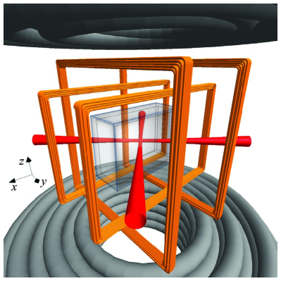
Each of the water-cooled quadrupole coils consists of 33 turns of inch-diameter coated hollow copper tubing. At a current of 425 A, the quadrupole coils (H) produce an axial field gradient of G/cm , which can be switched off completely within less than 1 ms using an IGBT. The bias-field coils are designed to provide a maximally homogeneous bias field, while minimally obstructing the optical access to the trap center for the given science cell geometry, as shown in figure 2. The outer (inner ) coils each consist of 25 (20) turns of 24 AWG (0.5 mm-diameter) magnet wire and are wound onto a stiff fiberglass holder structure. Each coil pair produces a field of 7.5 G/A at the center of the trap with a simulated field inhomogeneity of less than within a distance of 1 mm from the center. The air-cooled coils can thermally withstand ac currents of 8 A amplitude for the duration of the evaporation, corresponding to a 60 G bias field and a circle-of-death radius mm at the maximum quadrupole field.
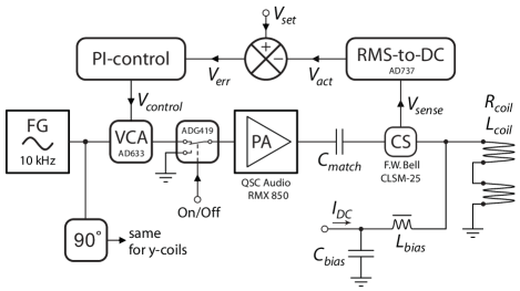
To drive the bias-field coils, we use an 800 W audio power amplifier (PA). For each coil pair, the impedance at the 10 kHz driving frequency is minimized down to the ohmic resistance by canceling the inductance with a matching capacitor. The measured inductance of the outer (inner) coil pair is H (H). The PA can easily supply the ac currents for a 60 G bias field directly into the resulting loads of , without the need for step-up transformers. The amplitude of the ac current through each coil pair is actively stabilized to within using the circuit outlined in figure 3. The regulation bandwidth of about 200 Hz is more than sufficient for compensating thermal drifts in the coil resistance 333An alternative, fast feedback scheme has been described in [19], where the focus is on reducing current noise to improve the coherence time for condensate interferometry in a special TOP waveguide [18].. The current can be switched off within less than 1 ms limited by the quality factor of the matched coil pair.
4 Condensate production in the McTOP trap
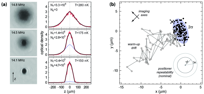
After transport into the science cell, the atom cloud typically contains atoms in the state at a phase-space density of . Forced radio-frequency (rf) evaporative cooling is initially performed in the stiff linear potential of the fully-compressed quadrupole trap (350 G/cm axial gradient), where it is more efficient until Majorana losses outweigh the advantage of a linear potential [21]. After a 14 s-long linear rf evaporation ramp down to a temperature of 75K and an atom number of , the phase-space density has increased to and the lifetime in the quadrupole trap due to Majorana losses has decreased to 35 s. At this point, the trap is converted into a TOP trap by switching on an 18 G rotating bias field, which preserves the atom number to within and the phase-space density to within a factor of two. The resulting harmonic trapping potential has measured trap frequencies of 70.4 Hz in the axial and 25.0 Hz in the radial direction. The trap parameters are held constant for the remaining 30 s of the evaporation sequence, during which another piecewise-linear rf ramp takes the cloud to quantum degeneracy, cf. figure 4(a).
We have found the shot-to-shot position reproducibility of the condensate to be consistent with the specified positioning uncertainty of the translation stages (m) once the system is warmed up, as shown in figure 4(b). For this measurement, the condensate was imaged simultaneously along two orthogonal axes in the horizontal -plane with standard resonant absorption imaging on the repump transition, immediately after the magnetic trap had turned off. We have not observed any systematic shifts of the condensate position caused by the “dual” imaging itself for the beam intensities used.
During the first 63 of a total of 173 consecutive runs after a cold start, the condensate position drifts by roughly m, as seen in figure 4(b). In the -direction we find a similar drift of about 7 m. This initial drift is directly correlated with the slow temperature increase and subsequent stabilization at C of the supply cables (4/0 AWG, i.e. 11.6 mm core diameter) of the quadrupole coils. As the cables warm up, their thick rubber insulation becomes much less rigid, thus changing the mechanical torque exerted on the coil holder. This potential problem can most easily be avoided by pre-warming the cables at high quadrupole coil currents.
We have found the condensate atom number to be stable to within - depending on the performance of the MOT. For optimized conditions, condensates containing up to atoms have been observed. No correlations were found between the atom number and the position jitter of the cloud in the science cell.
5 A retractable funnel for optical trapping
For condensate production in an optical trap, the evaporation in the McTOP trap can also be used as an intermediate step after which the quadrupole coils are moved out of the way. The stationary bias-field coils can then still be used to control the spin quantization axis, for example.
The experimental procedure is as follows. After RF evaporation in the magnetic potential, the atoms are loaded adiabatically into a crossed-beam optical dipole trap formed by two orthogonally intersecting laser beams. This is done by smoothly ramping up the optical potential over 400 ms and then smoothly ramping down the magnetic confinement over another 400 ms. After the transfer, the quadrupole coils are moved back to the intermediate position ‘b’ indicated in figure 1. The Gaussian laser beams of the crossed optical dipole trap (cf. figure 2) have a radius of m and a combined power of 3 W. They are derived from a single-frequency 1064 nm ytterbium fiber laser (IPG YLR LP-SF series) with a relative frequency offset of 20 MHz to average out interference effects. The depth of the optical trap, including gravity, is K in the horizontal and K in the vertical direction. This allows for efficient gravity-assisted evaporation of atomic clouds. We typically load the optical trap with clouds at nK and then ramp down the trap depth to K in the horizontal and nK in the vertical direction where condensation sets in. At this point, the trap is nearly isotropic with measured frequencies between 50 and 60 Hz. The loading procedure results in nearly pure condensates with atom numbers that are within 90% of those reached in the McTOP trap.
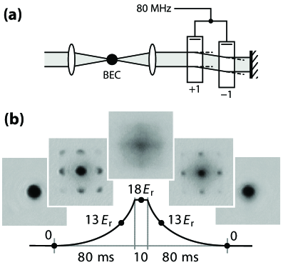
By performing the final evaporation in an optical trap, it is possible to easily use the TOP trap for optical lattice experiments, thus avoiding the usual drawback of TOP traps: atomic micromotion [23] can lead to strong heating due to an oscillatory motion of the atoms relative to the lattice at the frequency of the rotating bias field [24]. To demonstrate the suitability of the approach presented in this paper, figure 5 shows data for the superfluid-to-Mott insulator transition in a three-dimensional optical lattice [25, 26] obtained with our apparatus.
6 Conclusion
We have demonstrated a versatile and simple scheme for producing magnetically and optically-trapped condensates in a moving-coil transporter apparatus. In our scheme, the movable quadrupole coils are also used as an essential part of the final magnetic trap. As a stand-alone device, this trap reliably produces condensates with minimal technical complexity. In experiments with optically-trapped Bose-Einstein condensates, the quadrupole coils can be retracted before quantum degeneracy is reached, providing large optical access. The apparatus is well-suited for experiments with optical lattices, as demonstrated by observing the superfluid-to-Mott insulator transition.
References
References
- [1] Inouye S, Andrews M R, Stenger J, Miesner H J, Stamper-Kurn D M and Ketterle W 1998 Nature 392 151
- [2] Chang M-S, Hamley C D, Barrett M D, Sauer J A, Fortier K M, Zhang W, You L and Chapman M S 2004 Phys. Rev. Lett. 92 140403
- [3] Bloch I, Dalibard J and Zwerger W 2008 Rev. Mod. Phys. 80 885
- [4] Barrett M D, Sauer J A and Chapman M S 2001 Phys. Rev. Lett. 87 010404
- [5] Folman R, Krüger P, Schmiedmayer J, Denschlag J and Henkel C 2002 Adv. At. Mol. Opt. Phys. 48 263
- [6] Greiner M, Bloch I, Hänsch T W and Esslinger T 2001 Phys. Rev. A 63 031401(R)
- [7] Lewandowski H J, Harber D M, Whittaker D L and Cornell E A 2003 J. Low Temp. Phys. 132 309
- [8] Gustavson T L, Chikkatur A P, Leanhardt A E, Görlitz A, Gupta S, Pritchard D E and Ketterle W 2001 Phys. Rev. Lett. 88 020401
- [9] Streed E W, Chikkatur A P, Gustavson T L, Boyd M, Torii Y, Schneble D, Campbell G K, Pritchard D E and Ketterle W 2006 Rev. Sci. Instrum. 77 023106
- [10] Petrich W, Anderson M H, Ensher J R and Cornell E A 1995 Phys. Rev. Lett. 74 3352
- [11] Davis K B, Mewes M-O, Andrews M R, van Druten N J, Durfee D S, Kurn D M and Ketterle W 1995 Phys. Rev. Lett. 75 3969
- [12] Naik D S and Raman C 2005 Phys. Rev. A 71 033617
- [13] Lin Y-L, Perry A R, Compton R L, Spielman I B and Porto J V 2009 Preprint arXiv:0904.3314v1
- [14] Anderson B P and Kasevich M A 2001 Phys. Rev. A 63 023404
- [15] Klempt C, van Zoest T, Henninger T, Topic O, Rasel E, Ertmer W and Arlt J 2006 Phys. Rev. A 73 013410
- [16] Nakagawa K, Suzuki Y, Horikoshi M and Kim J B 2005 Appl. Phys. B 81 791
- [17] Esslinger T, Bloch I and Hänsch T W 1998 Phys. Rev. A 58 2664(R)
- [18] Reeves J M, Garcia O, Deissler B, Baranowski K L, Hughes K J and Sackett C A 2005 Phys. Rev. A 72 051605(R)
- [19] Baranowski K L and Sackett C A 2006 J. Phys. B: At. Mol. Opt. Phys. 39 2949
- [20] Ketterle W, Durfee D S and Stamper-Kurn D M 1999 Making, probing and understanding Bose-Einstein condensates Proc. Int. School Phys. “Enrico Fermi” Course CXL eds. M Inguscio and S Stringari and C E Wieman (Amsterdam: IOS Press)
- [21] Ketterle W and van Druten N J 1996 Adv. At. Mol. Opt. Phys. 37 181
- [22] Gemelke N, Zhang X, Hung C-L and Chin C 2009 Preprint arXiv:0904.1532v1
- [23] Müller J H, Morsch O, Ciampini D, Anderlini M, Mannella R and Arimondo E 2000 Phys. Rev. Lett. 85 4454
- [24] Cristiani M, Morsch O, Müller J H, Ciampini D and Arimondo E 2002 Phys. Rev. A 65 063612
- [25] Jaksch D, Bruder C, Cirac J I, Gardiner C W and Zoller P 1998 Phys. Rev. Lett. 81 3108
- [26] Greiner M, Mandel O, Esslinger T, Hänsch T W and Bloch I 2002 Nature 415 39