Hydrodynamic phase-locking of swimming microorganisms
Abstract
Some microorganisms, such as spermatozoa, synchronize their flagella when swimming in close proximity. Using a simplified model (two infinite, parallel, two-dimensional waving sheets), we show that phase-locking arises from hydrodynamics forces alone, and has its origin in the front-back asymmetry of the geometry of their flagellar waveform. The time-evolution of the phase difference between co-swimming cells depends only on the nature of this geometrical asymmetry, and microorganisms can phase-lock into conformations which minimize or maximize energy dissipation.
pacs:
47.15.G-, 47.63.Gd, 47.63.mf, 87.17.JjSwimming cells, such as spermatozoa or flagellated bacteria, are ubiquitous in nature, yet their dynamics in a world without inertia is often counter-intuitive Purcell (1977). Much insight has been gained in the past about the nature of the swimming of flagellated microorganisms, from the pioneering work of Taylor Taylor (1951), through to many detailed reviews on locomotion at the microscale Lighthill (1976); Brennen and Winet (1977); Lauga and Powers (2009). Spermatozoa in particular have received much attention in an effort to improve our understanding of the biomechanics of reproductive processes Fauci and Dillon (2006).
One particularly puzzling phenomenon observed in swimming spermatozoa and other microorganisms is the apparent synchronization of the beating of the flagella of two or more cells when in close proximity Taylor (1951); Yang et al. (2008). This phenomenon was first modeled by Taylor using infinite two-dimensional sinusoidal sheets Taylor (1951). Taylor found that the most energetically efficient configuration for two swimmers close together was to beat in synchrony. A computational model of the same setup showed that at small but finite Reynolds numbers, the sheets can achieve stable phase-locking at in-phase and opposite-phase configurations Fauci (1990), a result which remains valid for finite swimmers with flagella of linearly increasing amplitude Fauci and McDonald (1995). Computations in two dimensions showed that the flow fields of interacting swimmers tend to cluster them together into tight synchronized groups Yang et al. (2008). Large arrays of cilia (short, closely-packed flagella) also display synchronization if the internal force-generation mechanism generating their beat pattern is load-dependant Gueron et al. (1997); Vilfan and Jülicher (2006).
What is still not understood is what constitutes the essential physical ingredients to obtain an evolution in time to a phase-locked configuration between cells swimming close to each other. Here we consider a simplified model of nearby swimming cells with a prescribed waveform. We show that stable phase-locking can be obtained purely passively, due to hydrodynamic interactions. The phase-locked state to which the cells evolve is dictated solely by the geometry of the flagellar waveforms of the cells (specifically, their front-back asymmetry), and not by considerations of energy dissipation.
In the spirit of Taylor Taylor (1951), we consider a model of co-swimming cells consisting of two infinite parallel two-dimensional sheets propagating lateral waves of transverse oscillations with prescribed wavenumber , frequency , and wave speed ; each sheet is thereby propelled in the direction opposite to the wave. This idealized geometrical model, which has been used successfully in the past to study other properties of cell locomotion Lauga and Powers (2009), will allow us to clearly elucidate the necessary ingredients required for synchronization. We also relate it below to experimental observations.
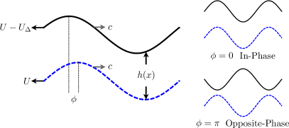
The shape of the waveform is assumed to be the same for both swimmers, and is described by an arbitrary function . The position of the bottom sheet relative to an axis about which it is centered vertically, is denoted in its swimming frame. The top sheet which is some mean distance above and parallel to the bottom sheet moves at a speed relative to the bottom sheet. The two sheets have an instantaneous phase difference denoted (see Fig. 1); is defined to be positive if the upper sheet moves to the right relative to the lower sheet; is defined to be positive if the upper sheet is left of the lower sheet by . The instantaneous position of the top sheet is thus given by , where is the phase difference at .
The governing hydrodynamics equations for low-Reynolds number flow in an incompressible Newtonian fluid are the Stokes equations, , for the velocity field, and pressure, . We non-dimensionalize using , , , , , , , where indicates the ratio of mean separation of swimmers to their wavelength, . Fluid force per unit width are nondimensionalized as and energy dissipation rate per unit width as . For convenience we introduce the variables , , . Consequently, we have , and , and the phase evolves in time according to . We further assume that the waveform possesses reflectional symmetry with respect to the horizontal axis, namely , in order to focus on cells swimming along straight lines Goldstein (1977). We now drop the (∗) notation for convenience, and refer to dimensionless variables.
As seen experimentally, phase-locking can occur when the cells flagella beat close together, therefore an appropriate limit to study is when the mean distance between them is much smaller than their wavelength, i.e. . In this limit the Stokes equations reduce to the lubrication equations, and Batchelor (1970). We solve these equations in a frame moving with the waveform of the bottom sheet Chan et al. (2005). The boundary conditions are hence and . The solution is for readily obtained as
| (1) |
Integrating the continuity equation over yields a relation between the gradient of the flow rate between the sheets, , and their relative motion as
| (2) |
In order to determine the physical conditions for phase-locking to occur, we first set and investigate the resultant horizontal hydrodynamic force, , acting on the upper sheet. In a free-swimming situation, the upper sheet would move at a rate such that the viscous drag would balance with (see below). With , we know from Eq. (2) that is constant and upon integrating Eq. (1) over we get . Since the system is periodic, we have , which leads to where . The pressure gradient is then obtained to be
| (3) |
The force per unit width is determined by integrating the stress over the upper sheet, , where is the unit normal to the sheet into the fluid and is the stress tensor. Using integration by parts, the force is given by
| (4) |
Using Eqs. (1) and (3), we finally obtain the force
| (5) |
Physical insight can be gained by inspection of Eq. (5). When (in-phase swimming), is constant, and the force is identically zero for all waveforms . Furthermore, since our waveforms possess reflection symmetries about the horizontal axis, the force is also exactly zero when (opposite-phase swimming). What is however the nature of the hydrodynamic force about the fixed points ?
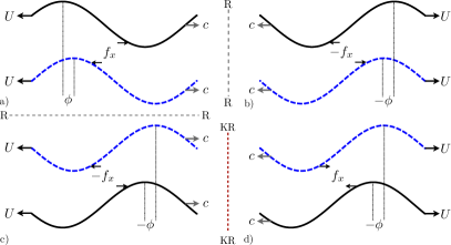
Using symmetry arguments, we can first demonstrate that if the waveforms also possess reflection symmetry with respect to the vertical axis (such as a pure sinewave), no phase locking is ever possible. This is illustrated in Fig. 2. Suppose the force between the swimmers acts to stabilize the phase difference (Fig. 2a). Let us then compare the forces on the setup obtained by a reflection by the vertical axis (Fig. 2b), with that obtained first by reflection by the horizontal axis and then by kinematic reversibility (i.e. change of the direction of the wave) (Fig. 2c and d). The force in Fig. 2d is destabilizing while the one in Fig. 2b is, for the same setup, stabilizing, indicating that both of them must be zero. In particular, sine-waves, such as the ones considered in Ref. Taylor (1951); Fauci (1990), cannot phase-lock. Note that this argument holds also for finite flagella with a shape invariant upon reflection about the vertical axis versus the horizontal axis, such as sine-waves with an integer number of wavelengths.
If the waveform is not front-back symmetric (i.e. lacks reflection symmetry with respect to the vertical axis), such as spermatozoa with flagellar waveforms of increasing amplitude Rikmenspoel (1965), the comparison between Fig. 2b and Fig. 2d cannot be made, and a force can appear. In that case, the comparison between Fig. 2a and Fig. 2c shows that this force must be an odd function of the phase difference, i.e. . For small variations about the fixed points, with , the force given by Eq. (5) determines the stability of . Near the in-phase configuration () the force is
| (6) |
to leading order in . If denotes the amplitude of the waveform, we see that , with a sign that depends solely on the wave geometry; the sign () leads to stability (instability) of in-phase swimming. Similarly, expanding about opposite-phase swimming (), we get at leading order
| (7) |
where . For small-amplitude waves with , Eq. (7) simplifies to
| (8) |
Comparing Eq. (6) with Eq. (8), we see that forces near in-phase and opposite-phase configurations have the same magnitude, but opposite signs. One of the fixed points for phase-locking is therefore stable while the other is unstable, in a manner which depends solely on the waveform geometry: If the waveform is such that () then in-phase swimming is stable (unstable) while opposite-phase swimming is unstable (stable) 111From kinematic reversibility we get that a stable fixed point for forward swimming is unstable for backwards swimming..
The rate of energy dissipated in the fluid between the sheets per unit width is , which is given over one wavelength by
| (9) |
For small-amplitude waves near in-phase swimming (), we get , while near the opposite-phase configuration (), we obtain . In-phase swimming is therefore always the situation where the swimmers have to do the least amount of work, while opposite-phase the most work Taylor (1951); Fauci (1990) 222Since the forces reverse upon a reversal of swimming direction, the energy dissipated is invariant under such a reversal.. Comparing this result with the forces in Eqs. (6) and (8), we see explicitly that there is no relationship between viscous dissipation and hydrodynamic force, and the swimmers can be forced into a stable conformation where the energy dissipation is in fact maximum (when ).
In order to observe the evolution of the phase angle towards a phase-locked state, we now allow to be nonzero. Evaluating Eq. (2) with Eq. (1) and integrating in we get
| (10) |
where is a constant, found by enforcing that the pressure is periodic, , where . We then obtain by imposing that the swimmers are force-free. Substituting Eqs. (10) and (1) into Eq. (4) with , we solve for and get
| (11) |
where
| (12) |
and refers to the force in Eq. (5). The change in the phase angle between the two sheets is therefore proportional to the force which would be acting between them if they were prevented from having any relative motion. For small-amplitude waves, we get , so that near the fixed points, the phase behaves as and we have near stable fixed points and near unstable points.
As discussed above, the geometry of the wave is the only factor determining the direction in which the relative position of the sheets evolve. For illustration, we now consider waves in the form of skewed sinusoids. We map a sinewave from the intervals and to the intervals and , and define on the interval . Shapes with () have a larger region where the wave amplitude increases (decreases) in the direction of the wave propagation (see Fig. 3, upper inset). If () then () and our analysis predicts that phase-locking will occur at the in-phase (opposite-phase) conformation. Experimental observations in Ref. Rikmenspoel (1965) suggest the flagellar amplitude of bull spermatozoa is reasonably given by a linearly increasing sine wave; this yields front-back asymmetry corresponding to . We now proceed to solve Eq. (11) numerically.
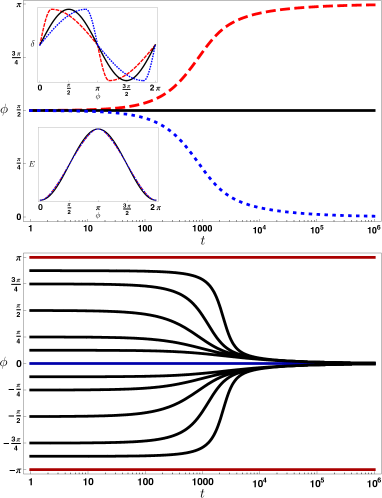
The dynamics of phase-locking is illustrated in Fig. 3 (top), where we plot the evolution of the phase angle from an initial phase for three shapes of swimmers (upper inset): perfect sinewave (, black solid line), and two skewed sinewaves with (blue dotted line) and (red dashed line). The perfect sinusoidal shape yields no evolution in time, as predicted by the analysis. In contrast, the skewed sinewaves evolve into the predicted phase-locked positions, in-phase for and opposite-phase for (at the same rate because the waveforms are symmetric to each other about the vertical axis). The energy dissipated between the sheets, Eq. 9, is displayed in Fig. 3 for the three shapes [lower inset]. The dissipation for the two skewed waveforms is identical – as is invariant under a reversal of swimming direction –, is slightly different from the perfect sinusoid (mean square difference ), and all shapes display the predicted maximum at and minimum at and . In agreement with our analysis, the numerical results demonstrate therefore that swimmers with increasing amplitude () phase-lock into the most energetically favorable conformation, while those with decreasing amplitude () phase-lock into the least energetically favorable conformation. The example with is further illustrated in Fig. 3 (bottom) where we show the evolution of the phase angle from various initial phases. In all cases, the configuration evolves into a phase-locked state at the only stable fixed point, . Further computations (not shown) show that increasing the asymmetry of the waveform, or its amplitude, decreases the time scale over which the systems evolves into a phase-locked state.
In summary, in this paper we have used a simplified model to show that hydrodynamic forces alone can lead to the observed phase-locking between two swimming microorganisms if their waveforms are front-back asymmetric. The nature of the phase-locked state, and the rate at which the relative conformation of the two swimmers evolve to it, is dictated solely by the geometry of the waveforms. In particular, an in-phase conformation may be obtained when the swimmers have shapes with increasing amplitude front to back, as observed for some mammalian spermatozoa Rikmenspoel (1965). Other front-back asymmetries, such as the presence of a head, would also further contribute to phase-locking Yang et al. (2008).
Discussions with T. Powers and S. Spagnolie and funding by the NSF (grants CTS-0624830 and CBET-0746285) are gratefully acknowledged.
References
- Purcell (1977) E. Purcell, Am. J. Phys. 45, 11 (1977).
- Taylor (1951) G. Taylor, Proc. R. Soc. Lond. A 209, 447 (1951).
- Lighthill (1976) J. Lighthill, SIAM Rev. 18, 161 (1976), ISSN 00361445.
- Brennen and Winet (1977) C. Brennen and H. Winet, Annu. Rev. Fluid Mech. 9, 339 (1977).
- Lauga and Powers (2009) E. Lauga and T. Powers, Rep. Prog. Phys. (to appear) (2009).
- Fauci and Dillon (2006) L. J. Fauci and R. Dillon, Ann. Rev. Fluid Mech. 38, 371 (2006).
- Yang et al. (2008) Y. Yang, J. Elgeti, and G. Gompper, Phys. Rev. E 78, 061903 (2008).
- Fauci (1990) L. J. Fauci, J. Comput. Phys. 86, 294 (1990).
- Fauci and McDonald (1995) L. J. Fauci and A. McDonald, Bull. Math. Biol. 57, 679 (1995).
- Gueron et al. (1997) S. Gueron, K. Levit-Gurevich, N. Liron, and J. J. Blum, Proc. Natl. Acad. Sci. U.S.A. 94, 6001 (1997).
- Vilfan and Jülicher (2006) A. Vilfan and F. Jülicher, Phys. Rev. Lett. 96, 058102 (2006).
- Goldstein (1977) S. F. Goldstein, J. Exp. Biol. 71, 157 (1977).
- Batchelor (1970) G. K. Batchelor, An Introduction to Fluid Dynamics (Cambridge University Press, 1970).
- Chan et al. (2005) B. Chan, N. J. Balmforth, and A. E. Hosoi, Phys. Fluids 17, 113101 (2005).
- Rikmenspoel (1965) R. Rikmenspoel, Biophys. J. 5, 365 (1965).