The Central Control of the MAGIC telescopes.
Abstract
The second MAGIC telescope, a clone of the first 17 m diameter MAGIC telescope, has entered the final commissioning phase and will soon start to take data, preferentially in the so-called stereo-mode. The control system for both telescopes is assigned to a number of autonomous functional units called subsystems. The control hardware and software components of the second telescope subsystems have been modified with respect to their counterparts of the first telescope. A new Central Control (CC) program has been developed to communicate with all the subsystems of both telescopes and to coordinate their functionality thus easing the stereo data taking procedure. We describe the whole control system in detail: all the subsystems and their communication with the Central Control, the CC graphic user interface that grants operators the full control over the two telescopes, and the automatic checking procedures, which guarantee the safety and ’health’ of the apparatus.
control system — MAGIC telescopes — stereoscopic system
1 Introduction
The MAGIC telescopes consist in two 17 m diameter
Imaging Atmospheric Cherenkov Telescopes (IACTs) located in the
Canary Island of La Palma ( 45’N, 54’W, 2225 m a.s.l.).
MAGIC-I is in operation since 2004, while MAGIC-II is still under
commissioning, even though it is already taking data.
The MAGIC telescopes, designed for the detection of Very High Energy
(VHE) -rays, have the largest light collection area, and consequently
the lowest trigger energy threshold among the current generation
of IACTs. The stereoscopic observation mode will lead to an improvement
in sensitivity by a factor 2 raising new challenges on the pulsar physics,
on the detection of more distant AGNs, and on physical
studies on weaker galactic sources.
Each telescope is composed of different autonomous components controlled
by their control programs. These functional units, described in section 2,
communicate with the Central Control (CC) program which coordinates the
actions of each telescope in order to automatize
the stereo data taking procedure as much as possible (see section 3). Nevertheless,
the CC graphic user interface confers the full control over the telescopes
on the operators. For example, they can configure the various components
of the telescopes according to the observation necessities. They can also stop
every kind of automatic procedure in case of problems during the data taking.
The role of the CC program is fundamental: it provides the user with a
simple interface to operate the telescopes in an orderly manner. On the other hand,
it defines all the standard observational procedures and the needed checks which
guarantee the safety and ”health” of the apparatus, as presented in section 3.1.
2 The Control System
The control system of the MAGIC telescopes is split up into
autonomous functional units, called subsystems. They control
the different components the telescopes are composed of: the telescope
drive system, the readout, the camera, the Active Mirror Control (AMC),
the data acquisition system and the calibration. The MAGIC-II subsystems
were upgraded with respect to the first telescope ones from either a
hardware or a software point of view. Some existing
problems were solved and their performance improved.
Moreover, there are the so-called ”common subsystems” which
collect information useful for the data taking, like the weather
conditions, the GRB alerts sent by different satellites, and the
absolute time given with high precision. All the subsystems,
classified according to their telescope belonging, are
described below.
The MAGIC-I subsystems are:
-
•
Telescope Drive System 1: it steers two ALT/AZ motors and monitors the telescope position using two shaft encoders and two rotary encoders over CANBus [1].
-
•
Active Mirror Control 1: two motors behind each mirror panel (40.5 mirrors) allow to counteract any deformation of the mirror support dish during repositioning and tracking. Each panel is equipped with a guidance laser in order to monitor the panel orientation. Moreover, the AMC includes four LEDs on the camera lid and a CCD-camera mounted on the reflector frame close to its center. All these component are connected to the control pc over RS-485 bus [2].
-
•
Camera and Calibration 1: the MAGIC-I camera comprises 576 Photo MultiPliers (PMTs) of two different sizes. The inner part of the camera is covered by 396 Field Of View (FOV) PMTs. The outer part is composed by 180 FOV PMTs [3]. The communication with the monitoring and configuring system of the pixels, and the calibration [4] is done via CANBus lines. The camera includes also a cooling system, two lids which cover the camera during day light and low voltages power. These three electronic components are autonomously controlled using several PLCs (Programmable Logic Controller) and the access to those PLCs is done using a protocol over RS-485 called Modbus.
-
•
Trigger system: The analog PMT signals are transmitted via optical fibers and divided by optical splitters at the counting house. Half of the signal is sent to the receiver boards which shape the signals through discriminator thresholds and send them to the level 1 trigger via Low Voltage Differential Signal (LVDS) system. The level 1 trigger is based on fast N-fold (N=2-5) next neighbor (NN) logic [5]. The triggered signals are then sent via LVDS to a VME system, connected through VME bus to the control pc, which allows to monitor and set the trigger parameters.
-
•
Mux DAQ: After having split the PMT signals, the second part of them is sent to the fiber-optic multiplexing readout system. The latter uses a 2GSample/s Flash Analog to Digital Converter (FADC) to digitize 16 channel consecutively. Within group of 16 channels, each analog signal is delayed of 40 ns with respect to the previous one by using optical fibers. These signals are then converted to electronic ones by using PIN diodes. Fast high bandwidth MOSFET-switches open for 40 ns channel by channel. Finally the signals are summed in two active summation stages and digitized by the FADC [6].
-
•
Sum Trigger: it is a second trigger system based on a new analog trigger concept which allows to reduce significantly the energy threshold. This trigger divides the camera in 24 semi-overlapping patches consisting in 18 pixels each. The patch analog signals are clipped at a certain amplitude to prevent accidental triggers from PMT-afterpulses, and then summed up. The analog sum signals are compared to programmable analog thresholds in semi-customized boards. The host boards communicate with a VME backplane for the readout of the patch rates and the threshold settings via a USB-VME bridge [7].
The MAGIC-II subsystems are:
-
•
Telescope Drive System 2: it steers two ALT/AZ motors and monitors the telescope position using a shaft encoder and two rotary encoders which communicate with a PLC via Profibus DP. The PLC is connect to the control program via ethernet [1].
-
•
Active Mirror Control 2: it works like in MAGIC-I, even though, instead of mirror panels, there are single 1 mirrors. This subsystem was improved a lot at the software level [2].
-
•
Camera 2: the camera of MAGIC-II is uniformly equipped with 1039 diameter PMTs [8]. The pixels are grouped into clusters of seven pixels each. Each cluster is controlled by a Slow Control Cluster Processor (SCCP) which monitors and sets all the PMT-related parameters. Also the camera lids are steered by SCCPs. These SCCPs are connected via LAN cables to a VME crate inside the camera box, which communicates to the camera control PC in the counting house via an optical PCI to VME link [9].
-
•
Readout system, calibration and trigger: from a hardware point of view the readout system is completely different from the MAGIC-I one. The PMT analog signals, transmitted by optical fibers to the counting house, are converted to electronic ones and split into two branches inside the receiver boards: one provides the input for the level one trigger (VME crate), the second one is sent to digitizing units. The triggered Cherenkov pulses are sampled at 2GSample/s by a Domino Ring Chip and temporarily stored in 1024 capacitors. The Domino chip is installed in the PULSAR boards which are VME interface boards [10]. A slow control program, called Magic Integrated Readout (MIR), is a multi-thread C-program which communicates with all the readout hardware components through the VME bus. The MIR steers also the calibration box which is connected to a VME crate in the counting house using a RS232 protocol over optical cables.
-
•
DAQ 2: it is a multithread C++ program, based on MAGIC-I Mux Readout, which reads the data samples from the readout hardware, performs an online analysis of the data and finally, stores the data in dedicated disk [10]. The achievable acquisition rate is 1kHz.
The ”common” subsystems are:
-
•
Pyrometer: Germanium lenses focus the radiation on thermoelectric sensor which measures the radiation temperature. Its integral flux defines the sky temperature. Another small sensor measures the air temperature and the humidity. This device, installed on the left side of the MAGIC-I mirror surface, is controlled by a PLC which communicates with the control program using a protocol RS-232.
-
•
GRB alert program: it is a daemon which monitors the Gamma-ray burst Coordinates Network (GCN) for any alert on GRBs. These alerts are promptly noticed to the Central Control providing the ”trigger” for the repositioning of the telescope.
-
•
Auxiliary PC: it collects information sent over a serial RS232 connection by a GPS receiver, a Rubidium atomic clock and the weather station. The two clocks provide the time stamp for the DAQs. The difference between both devices is monitored through a NIM module and reported to the auxiliary PC. The values are then written into a file.
The weather station is a microprocessor Weather Station MWS 5MV high quality steel with datalogger and forced ventilation by fan made by Reinhardt GmbH. The information collected by this device is read out over a serial connection by a program which writes the weather values onto a file. -
•
Level 3 coincidence trigger: it is the coincidence trigger of the two telescopes made of VME boards which are controlled by the MIR program.
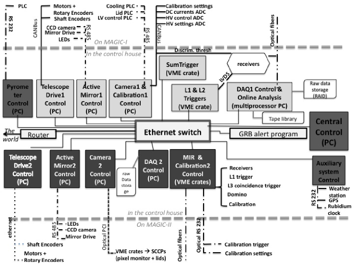
All the subsystems can be monitored and configured through their control programs which can be run in stand-alone mode for testing purposes, or remotely through the Central Control (CC) program. Each control program is installed in its correspondent PC in the counting house which is connected to the ethernet switch of the internal network. The scheme of the MAGIC control system is shown in figure 1.
3 The Central Control
The central control program is implemented in a Linux PC and written in LabView
8.5. It provides the user an easy graphical interface to operate the two
MAGIC telescopes.
The central control is the interface between all the subsystems which cannot interact
with each other. It communicates directly with each of them via socket connection, expect
in the case of the weather station and the clocks for which a file sharing is used.
At startup, it starts polling the other subsystems for availability. As soon as they are up,
the communication is established and this fact is displayed to the user.
Every subsystem sends an ASCII report to CC over ethernet using the TCP/IP protocol
every second describing its state, time stamp, and all relevant operation parameters.
This state variable is used to define the action of the subsystem. If
the central control does not receive any report from a subsystem for more than 10 s,
it defines the correspondent subsystem state as ”unavailable”.
By permanently updating the global subsystems state vectors, CC
keeps track of the state of the two telescopes and perform the needed actions
accordingly.
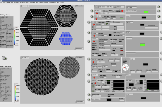
The received information, which is useful to determine the performance of the
telescopes during data taking, is displayed in the panel on the right
side of the Graphical User Interface (GUI), as shown in figure 2.
The top part of this panel includes all the ”common subsystems”, while below
all the information of MAGIC-I and MAGIC-II subsystems respectively are shown.
In particular, every subsystem has its own window inside the panel.
On the other hand, the two camera displays, on the left side of the GUI, can show
the information related to each pixel (voltages, currents, discriminator thresholds,
pulse arrival time, pulse charge, etc).
Moreover, the reports received by the central control during a data run are
written in a specific file and later on used as additional information for the offline analysis.
The central control sends a report every 10s to all the subsystems which, in this way,
can know when CC is available. Since the subsystems cannot communicate with
each other, the CC report is the only way they have to be aware of the state and some
useful parameters from a different subsystem.
Commands from CC to the other subsystems are executed by them as if the user
had given them directly at the consoles of the subsystems. In order to avoid accidental
interference, the subsystems, when controlled by CC, are locked from direct
interaction at their console.
The central control program contains routines which perform different actions,
needed for the data taking or for testing purposes, by sending a sequence of commands
to the involved subsystems. This automatization makes the operation of the telescopes
much easier and prevents possible human errors. Nevertheless, CC grants the
user full control of the telescopes, by allowing him to configure the system, to
stop any automatic procedure in case of problems and to skip it in case of particular
circumstances by sending single commands to each subsystem.
3.1 Automatic Checking Procedures
The central control performs decisional loops before sending any command in order to
check that the involved subsystem is in the correct configuration. These checks prevent
possible mistakes which can deteriorate the data quality and avoid that the command
will be unsuccessful.
Moreover the parameters delivered by the subsystems are compared to safety limits or standard
values and warning or safety reactions result when the parameters seem to show problematic states.
For example, if the external humidity, measured by the weather station, exceeds a certain value, the
electronic inside the camera can be damaged. Therefore, the lids, which protect the camera, will
be automatically closed. If the sun is still present, the system does not allow the operator
to rump up the high voltage in order not to ruin the PMTs. If the wind speed is too high, this can provoke
strong damages to the telescope structure and to camera lids if they are opened. In this case CC closes
the lids and park the telescope.
4 Acknowledgement
We would like to thank the Instituto de Astrofisica Canario (IAC) for the excellent working conditions at the Observatorio del roque de los Muchachos in La Palma. The support of the German BMBF and MPG, the Italian INFN, and Spanish MCINN is gratefully acknowledged. This work is also supported by the ETH Research Grant TH 34/043, and by the YIP of the Helmholtz Gemeinschaft. The authors would also like to thanks all the MAGIC colleagues who made this work possible.
References
- [1] Bretz, T. et al. The drive system of the Major Atmospheric Gamma-ray Imaging Atmospheric Telescope. Astropart.Phys.31:92-101,2009.
- [2] Biland, A. et al. The Active Mirror Control of the MAGIC Telescopes. 30th ICRC Proceedings.
- [3] Cortina, J. et al. Camera Control and Central Control of the MAGIC Telescope. 28th ICRC Proceedings.
- [4] Gaug, M. et al. An Absolute Light Flux Calibration for the MAGIC Tele- scope. 28th ICRC Proceedings.
- [5] Paoletti, R. The Trigger System of the MAGIC Telescope. IEEE transactions on nuclear science, vol. 54, no. 2, April 2007
- [6] Goebel, F. et al. Upgrade of the MAGIC Telescope with a Multiplexed Fiber-Optic 2 GSamples/s FADC Data Acquisition system. 28th ICRC Proceedings
- [7] Rissi, M. et al. A New Trigger Provides a Lower Energy Threshold for the MAGIC Cherenkov Telescope. Nuclear Science Symposium ’08 proceedings.
- [8] Borla-Tridon, D. et al. Performances of the Camera of the MAGIC-II Telescope. These proceedings.
- [9] Steinke, B. and Jogler, T. MAGIC-II Camera Slow Control Software. These Proceedings.
- [10] Tescaro, D. et al. The readout system of the MAGIC-II Cherenkov Telescope. These proceedings.