Deterministic reordering of 40Ca+ ions in a linear segmented Paul trap.
Abstract
In the endeavour to scale up the number of qubits in an ion-based quantum computer several groups have started to develop miniaturised ion traps for extended spatial control and manipulation of the ions. Shuttling and separation of ion strings have been the foremost issues in linear-trap arrangements and some prototypes of junctions have been demonstrated for the extension of ion motion to two dimensions. While junctions require complex trap structures, small extensions to the one-dimensional motion can be accomplished in simple linear trap arrangements. Here, control of the extended field in a planar, linear chip trap is used to shuttle ions in two dimensions. With this approach, the order of ions in a string is deterministically reversed. Optimised potentials are theoretically derived and simulations show that the reordering can be carried out adiabatically. The control over individual ion positions in a linear trap presents a new tool for ion-trap quantum computing. The method is also expected to work with mixed crystals of different ion species and as such could have applications for sympathetic cooling of an ion string.
pacs:
03.67.Ac 03.67.Lx, 05.60.Gg, 37.10.Ty1 Introduction
Ion traps hold great promise for realising scalable quantum computing and, in most regards, stand as the pre-eminent system for such applications [1]. The essential building blocks required for quantum computing [2] have been realised using linear strings of a few ions [3, 4]. To fully exploit the power of trapped-ion quantum computing, such methods must be scaled to involve many ions which can be made to interact with one another in different combinations according to the requirements of any particular algorithm [5]. One way of achieving this is to divide the traps into segments, so the ions can be moved and sorted into arbitrary arrangements [6]. In such a system the ability to reorder ions within a single linear ion string is a highly valuable tool: an ion that carries quantum information may be passed from one side of an ion string to the other. While it may seem that such information may instead be passed through the quantum channel provided by the common ion motion [7], the mechanical method has the advantage that it neither depends on the electronic encoding scheme, nor relies on precise knowledge of the trap parameters. This renders the mechanical method very general. Additionally, ions of different species can be interchanged. This feature may be of use for sympathetic cooling applications, where the cooling ions need to be correctly placed within a longer ion string. While there is a method of sorting ions of different masses within an ion string through simple Doppler cooling [8] this scheme does not apply to ions of similar masses, e.g. 40Ca+ and 43Ca+, as recently used for sympathetic cooling [9]. Additionally, it cannot achieve arbitrary arrangements of ions, such as an arrangement with all ions used for sympathetic cooling situated at the same end of the string, as is required with, e.g. ion-trap implantation techniques [10].
In order to interchange the positions of two ions, the ions have to be moved in (at least) two dimensions. Such 2D-movement can be achieved in trap architectures that have been specifically designed for this purpose such as, e.g. T-shaped [11, 12] or X-shaped [13] junctions of linear traps. The reordering of two ions can be achieved by separating a pair of ions and shuttling them through the junction. Such junction structures are, however, technically demanding to fabricate. Additionally, the potential near the junction is rather complicated and highly sensitive to (mis)alignment during trap construction. This can lead to the requirement for careful calibration of the voltages for each individual path [11, 13]. In [11], using a T-shaped junction comprising of three layers of electrodes an exchange success rate of 24% is reported, together with a heating rate of 1 eV per turn. The heating rate is caused by an RF barrier that—due to the large size of control electrodes in the junction region—can only be overcome in a non-adiabatic fashion. Using a fabrication process which allows narrower electrodes, the group of D. Wineland has demonstrated that single ions can be reliably shuttled through an X-shaped junction generated by a two-layer electrode design [13]. Using fast transport and low-noise RF sources the heating rate was brought down to 15 quanta. Nonetheless, the method still requires complex trap structures and rather involved electrode-voltage control to ensure low heating rates over the RF barrier. The ability to deterministically arrange ions within a string using a linear trap would provide a valuable new tool for segmented ion-trap technology, significantly simplifying the hardware requirements.
In this paper two methods of deterministically reordering ions within a linear, segmented, planar ion trap are presented. The trap geometry used [14] consists of only 5 segments (i.e. RF plus 11 independent DC electrodes) and has no junction structures. In both methods the ion string is reversed by an adiabatic change of the trapping potential. In the first method the trapping potential is rotated about its centre point by appropriately tailoring the electrode voltages. The technique of rotating an ion string about its centre is attractive for a number of practical reasons. Specifically, the optimisation of the electrode voltages requires the electric fields to be modelled (or measured) only at a single point. It is also simple to image the ions during the entire turn, to aid experimental optimisation of the control voltages. For other realisations of ion reordering [11, 13] the fields must be considered over an extended path, and imaging the ions at all points of the turn is more involved or even impossible. The second method demonstrated in this paper is akin to a “three-point turn”. Here the orientation of the principal axis with weakest curvature varies as a function of space, and the ion string is reoriented by exploring this spatially varying field. The position is controlled only by time-dependent homogeneous fields. Were these applied to an array of traps it might be possible to parallelise reordering of ions in multiple traps.
2 Apparatus
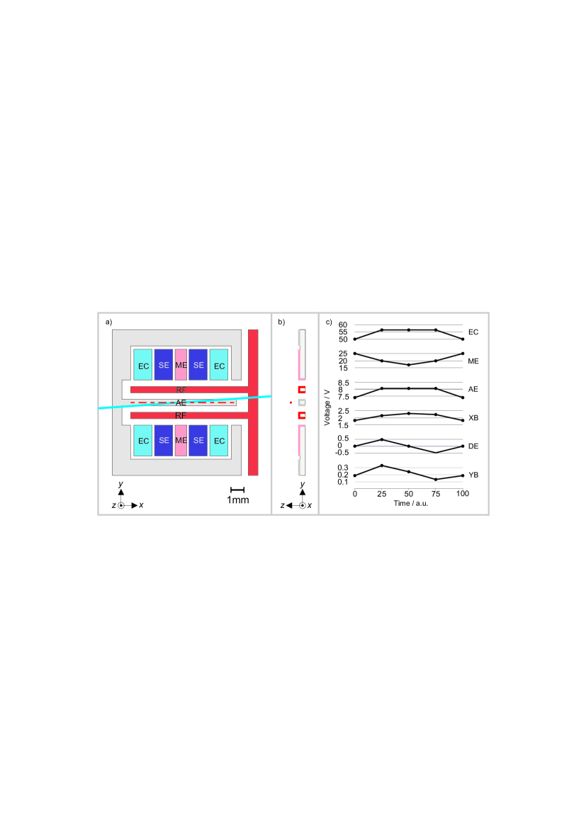
For both reordering methods the ions are held in a linear, segmented, planar ion trap which consists of 5 segments, as shown in figure 1(a-b). The electrodes are made of copper on a vacuum-compatible printed-circuit-board substrate, with an ion-surface distance of around 830 m [14]. A radially confining potential is produced by an RF voltage of amplitude V (0-peak) and frequency = 10.125 MHz applied to the RF rails (figure 1 RF). The voltage amplitude is measured using a capacitive divider just before the vacuum feedthrough. There is 10% uncertainty on the value of the RF voltage at the trap. Axial confinement is provided by a DC voltage of 55 V applied to the four endcap electrodes (figure 1 EC). DC voltages of up to 25 V are applied to the remaining 7 electrodes to tailor the potential. This set-up yields typical motional frequencies around (, , ) = 2(120, 230, 790) kHz (where the subscripts denote motion in the directions as defined in figure 1). The values of the DC voltages are controlled by two analog output boards (National Instruments, NI-PCI6733). These voltages are then filtered by RC filters with a cut-off frequency of 1 kHz, situated outside the vacuum chamber, around 25 cm from the trap.
The energy levels of 40Ca+, and the laser systems required for cooling and manipulation of the ions, are described in detail elsewhere [15], and summarised here. Laser light at 397 nm is used for Doppler cooling and state detection on the S1/2–P1/2 transition, with a repumper laser at 866 nm tuned to the D3/2–P1/2 transition. A laser at 729 nm is used to excite the ion from the ground state, S1/2 (hereafter referred to as ), to the long-lived D5/2 state, (). Light at 854 nm can then be used to quench the state and to rapidly return the ion to the ground state via the P3/2 state. All laser beams are parallel to the surface of the trap, and at an angle of 4∘ to the -axis, as defined in figure 1(a).
Fluorescence light at 397 nm is imaged using a custom-made lens (f# = 1.7, NA = 0.28, focal length 67 mm) onto a CCD camera (Andor iXon DV885 JCS-VP) to provide a resolution of 2 m per pixel. The ions’ micromotion is coarsely minimised in the -direction by ensuring that the position of the ions observed on the camera does not vary as a function of RF power [16]. The height of the ions above the trap (-direction) is adjusted to ensure that the ions are well crystalised (i.e. each individual ion’s image is well localised on the CCD camera).
3 One-point turn in a planar trap
To perform a rotation of the ion string the trap’s axial confinement (along ) is steadily increased until it is stronger than the weakest axis of the radial confinement (along ), so that the ion string is aligned perpendicular to the radio-frequency null axis. Diagonal pairs of electrodes are used to ensure that—as the axial confinement is changed—the ion string smoothly aligns itself to the appropriate direction. When the axial confinement is relaxed, opposite voltages of the diagonal electrodes cause the ion string to continue its rotation, and finally to reach its original position with reversed order.

To easily control and understand the action of the four so-called “steering electrodes” (figure 1 SE), their voltages are defined in a particular basis as illustrated in figure 2. The configurations are termed: offset, in which the potential of all four electrodes is moved together; x-balance, in which a potential difference is applied between the left and right electrode pairs; y-balance, in which a potential difference is applied between the top and bottom pairs; and diagonal, in which a potential difference is applied between the diagonal pairs. The offset has the effect of moving the ions along the -direction, and the - and -balance move the ions in the plane of the trap. The diagonal configuration creates a potential with a saddle point at the middle of the trap, oriented with axes of symmetry at 45∘ to the - and -directions. This allows the principal axes of motion to be rotated smoothly between and .
A typical set of voltages used to perform a turn is shown in figure 1(c). A qualitative explanation of the voltages required is as follows. The very high confinement along the -axis (perpendicular to the substrate) compared to that along the two directions parallel to the substrate ( 3.5, 6.5) means that, even for reasonably large variations (several volts) in the DC potential, the confinement in remains strong compared to that in both and . This largely simplifies the problem so that only the --plane need be considered. As detailed in section 6 the crucial part to achieve an ion rotation is a sufficient compression along the RF null (here, the -axis) as compared to the weak radial axis (here, the -axis). For the given trap layout this compression is best reached by a combination of increasing the endcap electrode voltage (figure 1 EC) and decreasing the middle electrode voltage (figure 1 ME). Between the two extremes (aligned along , aligned along ) the diagonal electrodes are used to smoothly vary the principal axes of the ions’ motion. Given the asymmetric nature of the trap (i.e. that all electrodes are situated in a single plane below the ion) a change in the endcap and middle electrode voltages also affects the height of the ions above the trap surface (-direction). The axial-electrode voltage (figure 1 AE) is adjusted to ensure that the ion string remains well crystalised. Finally, to compensate for the effects of any static or patch charges, or any imperfections in the trap fabrication, the - and -balance are set to ensure that the ion string stays centred on a single position during the turn.
To create the voltage ramps required for a turn, a string of three or more ions is observed with the CCD camera, and the electrode voltages are adjusted in real time to place the ions in certain key positions (namely, centred on a fixed point, with rotations of 0∘, 45∘, 90∘ and 135∘). In addition to constraining the centre position and angle of the string, voltages are chosen to ensure that the string remains in a linear configuration, rather than adopting a zig-zag form. This sets a lower bound on the ratio of the transverse to longitudinal motional frequencies [17]. In the case of a 3-ion string this is 1.6. A linear interpolation between the electrode voltages for the key positions is then made, to give a continuously varying ramp, as shown in figure 1(c). Using these voltage ramps the ion positions were exchanged and a pair of ions traced out the paths shown in figure 3. The rotation of the ions is also shown as an animation in the online material. The inter-ion separation varied between 21 and 31 m. Correspondingly, the longitudinal frequency of the chain varied in the range 75 kHz 125 kHz.
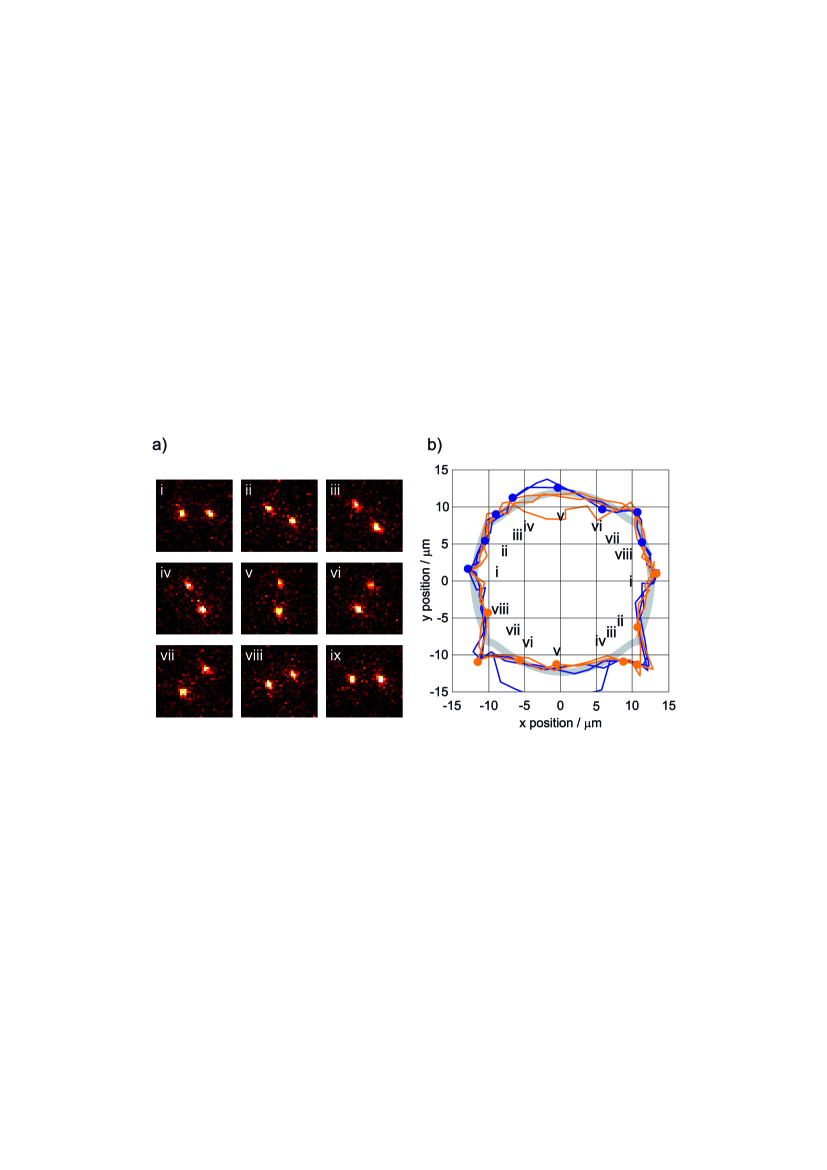
The path measured in the experiment agrees well with boundary-element method simulations, carried out using CPO111Charged Particle Optics Version 7.1. Free version available at www.electronoptics.com. For these calculations, the DC potential was simulated using the exact potentials applied to the DC electrodes. There is a small uncertainty for the RF drive voltage. We display the path for an RF voltage of = 300 V, which best fits the observed ion positions and is, within the error margin, consistent with the measured value of 320 V. Equally, the -position, information about which is not accessible through our camera observation, has been assumed to be constant at = 880 m, in close proximity to the expected height of the RF null, =830 m. With these values, the calculated ion positions are very close to the ones observed, as shown in figure 3(b). Given this ability to model the potentials, the voltage ramps can in principle be optimised to yield constant longitudinal and transverse frequency during the rotation. Theoretical considerations regarding the realisation of such smooth rotations are given in section 6.
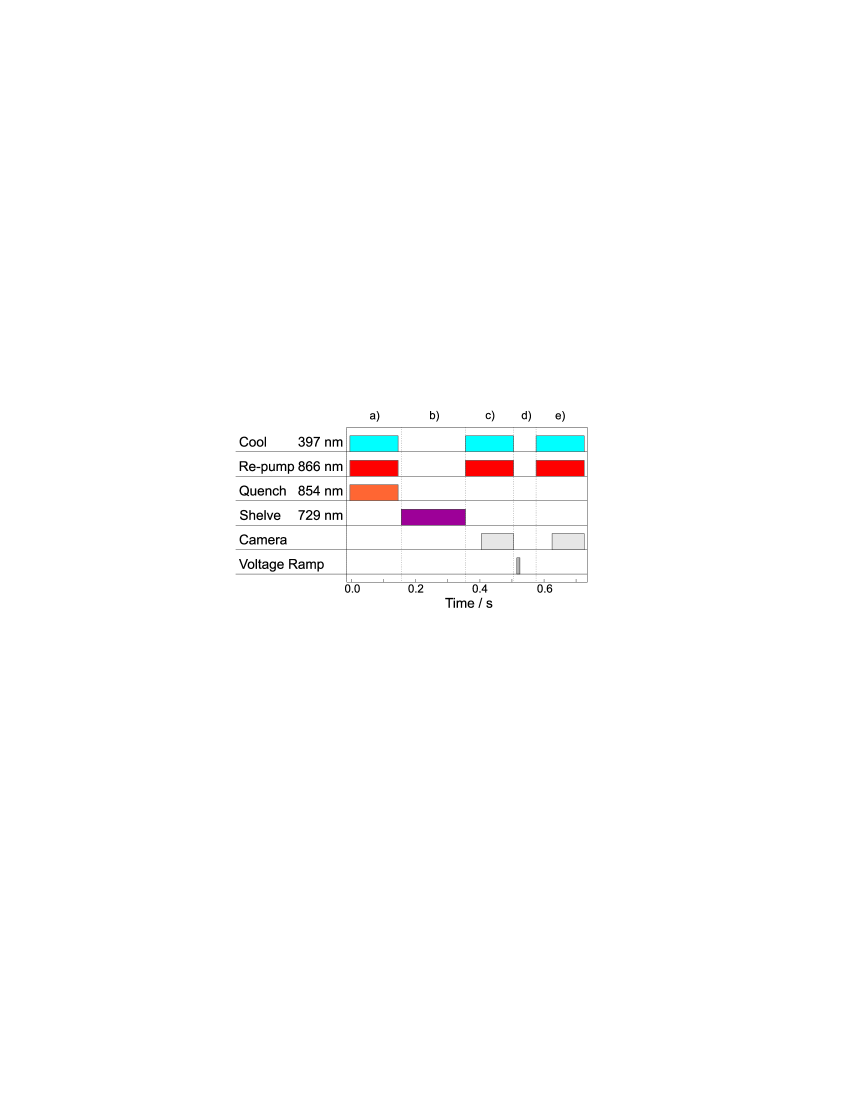
To measure the fidelity of the procedure, an exchange of a pair of Doppler-cooled ions is performed without laser illumination. First the ions are Doppler-cooled and, by means of the repump laser at 854 nm, prepared in the state (figure 4(a) ). Next a 729 nm laser pulse is commonly addressed to both ions so that each ion is independently excited to the state with an average probability of 20-50% (b). An additional Doppler-cooling period with camera detection is then used to select the cases in which exactly one ion has been shelved (c). The ion chain is then rotated (d) and again imaged to identify the position of the shelved ion (e). Cases in which the shelved ion has decayed back to the state are disregarded as they contain no information.
With this method, the fidelity of exchange was determined to 97% (433 events), and within the counting statistics, no significant dependance on the direction of the turn was observed (clockwise: 189/193, anticlockwise: 232/240). Furthermore, the fidelity showed no dependence on the exchange time, , in the range 1.5 ms 20 ms. Below 1.5 ms the fidelity dropped rapidly due to the low-pass filters significantly altering the waveform applied to the electrodes. From numerical simulations, described in section 4, we believe that the exchange could be made a factor of ten times faster if the filters were adapted in frequency and the reorientation of the trap axis was performed in a smooth way. For motional frequencies as high as those used in [13], the reordering could be performed within as little as 10 s. It is worth noting that such a time scale is fast even compared to a conventional coherent swap gate [18, 19].
If the ions were held for the duration of the exchange routine, without applying the exchange voltage-ramp sequence, the probability that they maintained their original ordering was measured to be 97% (182 events). The fidelity of the exchange seems therefore to be presently limited by the rate at which the ions are able to exchange positions within the standard linear trap. The origin of this stochastic exchange mechanism has not been fully investigated, although it may be attributable to the comparatively high background pressure of mbar and to imperfect Doppler cooling, particularly in the radial directions, due to the orientation of the Doppler-cooling beam.
4 Induced heating
Beyond the efficacy of the reordering, a figure of merit for the swap operation is the ion-heating induced by the time-varying potentials. In performing a turn as described, the ions necessarily leave the RF null by half the inter-ion distance (here, by 12 m). Carrying out a turn with a greater number of ions will lead to even larger excursions into regions of significant RF potential. It may be thought that, while the micromotion is conservative for a single ion, micromotion could nonetheless couple to secular motion if there is more than one ion in trap, and cause heating [16]. However, for crystals with small ion numbers (5) the micromotion-driven motional spectrum has been shown to be dominated by a small number of discrete frequencies and—being essentially integrable—offers no heating mechanism in the absence of laser light [20, 21]. By leaving the RF null the ions, for the exchange operation parameters described above, the ion traverses an effective RF barrier of 0.4 meV. The lack of heating across this barrier is confirmed by numerical simulations of an ion exchange using optimised electric fields which preserve the trap frequencies given above (the full description of the fields is given in section 6).
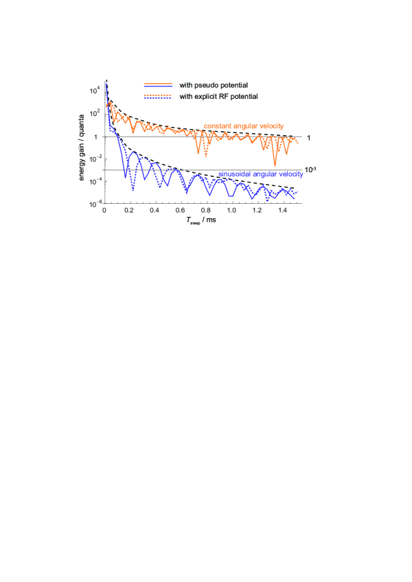
The classical path of two trapped ions has been computed for different durations of the swap, and the total acquired energy (kinetic plus potential energy) at the end of the sequence is calculated. Figure 5 shows the acquired energy in units of longitudinal vibrational quanta, . The two upper curves refer to a swap with constant angular velocity throughout the turn, i.e. with an abrupt start and stop. The two lower curves result from a rotation with angular-velocity that varies according to the first half of a sine function. For both cases, the dynamics have been computed using first the pseudopotential approximation, and subsequently the full time-dependence of the RF field. The results show differences in the detailed structure, while the envelope for the acquired energy is unchanged by the explicit inclusion of the radio-frequency. At an exchange duration of =1.5 ms, even for abrupt velocity changes, a total energy gain equivalent to only one motional quantum is predicted. For smooth variation of the trap orientation the same low degree of heating can be reached with a swap duration of 120 s. This constitutes a near-adiabatic exchange of the ions.
While no direct heating measurements have been made in our apparatus, an upper limit on the heating rate induced in the experiment was inferred by a sequence of 200 consecutive exchanges performed after previous Doppler cooling. The sequence was repeated 149 times before an ion was lost from the trap. Computer simulations for the specified operating conditions yield a trap depth of 1 eV. Assuming a thermal distribution of the ions’ kinetic energy after the 200 swap operations, the observed loss rate suggests a final mean kinetic energy of not more than 150 meV, at the 99% confidence level. Additionally assuming a linear heating mechanism, this corresponds to an estimated heating rate upper bounded by 0.8 meV per exchange. Even this upper bound compares favourably with the heating rate of 1 eV per exchange reported when reordering ions through a T-junction [11]. The significant difference in heating is because the large electrode extent in [11] precluded adiabatic shuttling over the RF barrier. The estimated upper bound in our experiment is still almost four orders of magnitude above the heating rate measured when moving pairs of ions through an X-junction [13], and five orders of magnitude above the calculated optimal transport protocoll for this trap. For proper comparison of methods, more precise temperature measurements would need to be made.
5 Three-point turn in a planar trap
Rather than creating a variable trap anisotropy at a given point by changing all of the electrode voltages, the electrodes can be set such that the trap anisotropy varies spatially in an appropriate fashion. The - and -balance (which generate negligible quadrupole components over the region of interest, and thus do not significantly alter the anisotropy themselves) are used to move the ions to different points in this spatially varying potential. Typical voltages are shown in table 1. These (excluding - and -balance) provide the background potential. The path taken by the ions is shown in figure 6. At the starting position (a) the ions are aligned along the -axis, while at point (c)–100 m away–they are aligned along . To move directly from (a) to (c) would cause the ions to jump randomly to 90∘. The reordering can be made deterministic by passing through the off-axis points (b) and (d) in figure 6. With this method an exchange fidelity of 93% was observed. This value is limited by the relatively small anisotropy attained near the intermediate points (b) and (d), i.e. at these points the ratio of the longitudinal to the lower transverse motional frequency approaches unity, so that the trap orientation is only weakly defined. In principle, the reliability of exchange can be improved by optimising the path taken, to keep this anisotropy consistently high. While under the given conditions this method may not seem preferable to the rotation about a point on the RF null, it illustrates that ion strings may be taken well away from the RF null for a short excursion. This adds flexibility to the net potentials seen by the ions, and may be particularly interesting at a junction between two linear radio-frequency traps. The use of spatially homogeneous potentials may also find applications for parallel control of many operations in arrays of traps.

6 Considerations for a turn in a three-dimensional segmented trap
In the planar trap that is used in these experiments the ion movement is easily confined to two dimensions because the confinement along the -axis (perpendicular to the trap surface) is by far the strongest, as described above. This is due, in part, to the ions being situated outside of the plane of the electrodes, far from the symmetry axis of the trap structure (as seen in figure 1(b) ). In many other trap geometries, however, the ions are trapped on the physical symmetry axis of the electrode structure, e.g. in two-layer segmented traps [22, 23, 24]. It is therefore important to consider whether the ability to perform the ion string rotation arises from the fact that the ions are trapped away from the symmetry axis of the electrode structure, or whether the results demonstrated here can be generalised to other trap geometries. As a particular example, the segmented Paul trap dedicated to single-ion implantation into crystals [10] requires dopant ions to be sympathetically cooled by 40Ca+ ions before being expelled towards the target. For these experiments it would be a real advantage if a reordering strategy similar to the one presented here could be implemented.
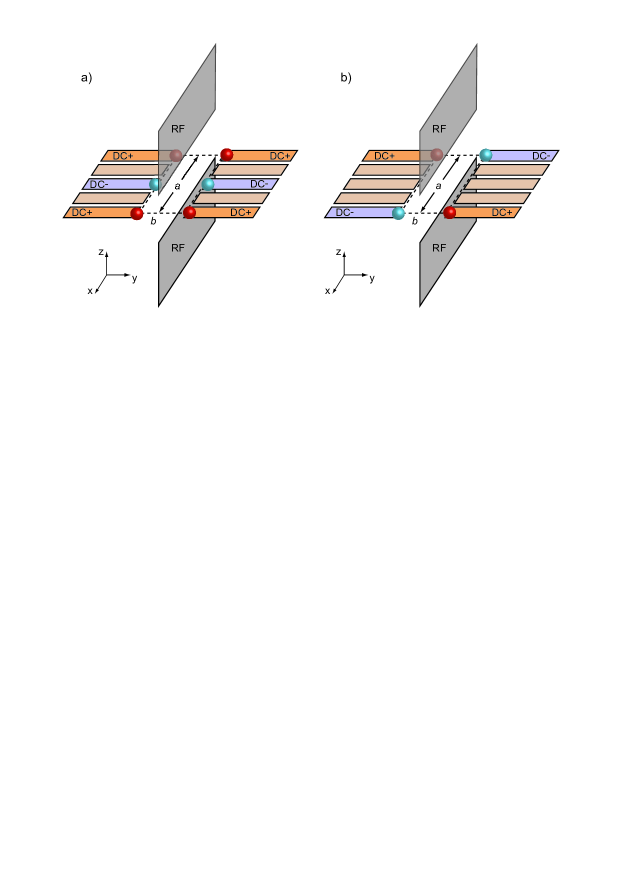
In the following, the general requirements for the rotation of an ion string are considered, and appropriate geometries to generate the required fields in a three-dimensional segmented trap are discussed. A generic geometry, as illustrated in figure 7, is assumed (this also directly translates into standard two-layer segmented traps), and a simple point-charge model is used to choose the optimal spacings for the control electrodes. In this geometry the pseudopotential due to the radio-frequency voltage confines the ions along the - and -axes, and leaves them free along the -axis. Maxwell’s equation, in free space, then requires that the radio-frequency confinement along and is equal. The DC voltages on the segmented electrodes lead to an additional confining or repelling potential and, again from Maxwell’s equation, it follows that the net sum of this potential’s curvatures along the three axes is zero.
The DC potentials can be used to continuously rotate the weakest trap axis so that the ion string smoothly follows the orientation of the trapping potential. During rotation, a minimum ratio of the second-lowest to lowest trap frequency must be preserved to prevent the ion string from folding into a zig-zag configuration [17]. When the ion string is oriented transverse to the RF null, the DC confinement along the RF-null axis (here ) has to be strongly increased, while it is weakened along one radial axis – in the following labeled -axis. Moreover, the curvature of the potential along the principal trapping axes (i.e. the -axis and the two time-dependent principal axes in the --plane) should be kept constant in order to avoid heating.
Such a rotation of the axes can be achieved by a time-dependent two-dimensional quadrupole field, , with its principal axes in the --plane. As will be shown below, this field can be created from the superposition of two separate quadrupole fields, in the following labeled and , with the principal axes oriented along , for the first field, and diagonal to these for the second field. In a typical three-dimensional segmented trap, the required potentials can be created by appropriate voltages on six DC electrodes as illustrated in figures 7 and 8. The field to be added can thus be written as
| (1) |
To establish this result, and the ideal time evolution of the relative quadrupole amplitudes and , a linear ion trap is considered, where an initial potential, , confines the ions aligned along the -axis. The desired potential, , is simply the initial potential, , rotated by an angle, , around the -axis. The additional potential, , required to achieve this rotation is determined through the relation
| (2) |
The initial effective potential, , is given by:
| (3) | |||||
| (4) |
with, in general, three different curvatures, , that are the sum of curvatures and arising from the static potential and the RF pseudopotential, respectively.
In order to transform this potential into one where the ion string is aligned along the -axis, the respective potential curvatures along the - and -axes need to be swapped. This is exactly achieved by a two-dimensional quadrupole field oriented along these axes,
| (5) |
where the curvature .
This transverse quadrupole field alone is, however, not sufficient to smoothly rotate the ion trap to its transverse position. The mirror symmetry about the --plane needs to be broken in order to define the direction of rotation. This is achieved by a second two-dimensional quadrupole field, , of same strength that has its axes rotated by 45∘ with respect to and . This calculation is facilitated using quadratic forms:
| (6) |
The two quadrupole fields are then characterised by the two square matrices
| (9) | |||||
| (12) |
where denotes the matrix for an anticlockwise rotation about the angle :
| (13) |
(The diagonal quadrupole potential is then .)
The additional potential, , needed to transform the initial trapping potential into one rotated by an angle , is given by equation 2 and is thus expressed through the square matrix
| (14) |
which finally equates to
| (15) |
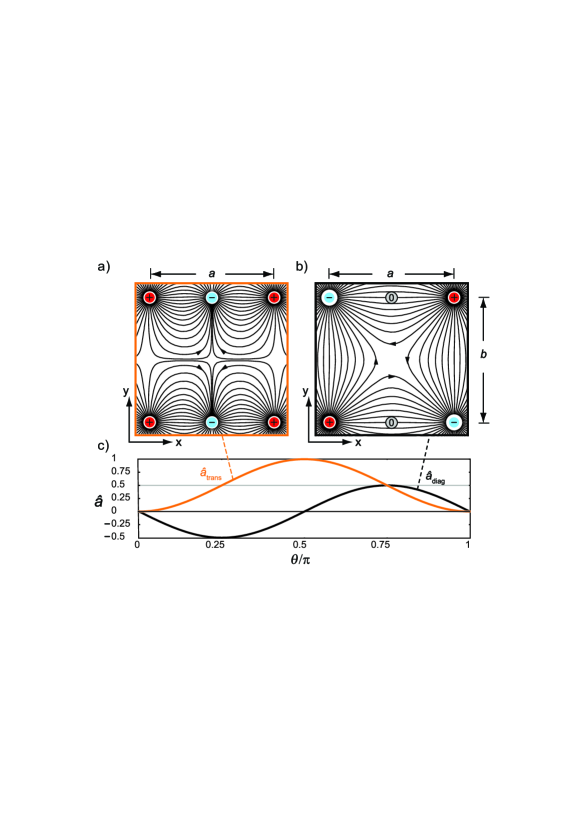
This result shows that smooth rotation of the ion trap about an angle is achieved by a potential that is a time-dependent superposition of the two quadrupole fields, and . For the desired evolution, the amplitudes and need to oscillate sinusoidally at twice the rotation frequency of the trap axis and with a relative phase shift of . Figure 8(c) illustrates the evolution of these amplitudes during a half rotation of the trap (i.e. one swap operation). The positive offset for can be understood as an offset to render the trap circular in the plane of rotation before adding a purely rotating two-dimensional quadrupole field.
One may now determine an optimum layout of electrodes to generate the two quadrupole fields required for the trap rotation. For a linear segmented trap a set of six electrodes is considered, as sketched in figure 7, that is supplied with two different voltage configurations in order to produce the transverse (a) and the diagonal (b) quadrupole field, respectively. To estimate the resulting potential the electrodes are approximated by six (four) point charges that are proportional to the applied voltage. The effect of the electrodes’ spatial extent, the leads and the shielding by the radio-frequency electrodes is neglected. For these simplifying assumptions the curvatures of the DC potential can be calculated analytically, and the resulting fields are illustrated in figure 8(a) and (b) respectively. The geometry is characterised by the aspect ratio of the outermost electrodes’ spacing, .
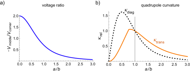
In order to create the transverse quadrupole field (figure 7(a) and 8(a) ), the four corner electrodes are positively charged, while the inner electrodes are provided with negative voltage. When the ratio of inner to outer electrode voltages is adapted to the electrode aspect ratio as depicted in figure 9(a) (, the resulting field in the centre will be a two-dimensional quadrupole field as required (the calculation of this is given in the appendix). The physical limitation for the fields created is typically given by a maximum voltage that can be applied to the DC electrodes. For aspect ratios the outer electrodes have higher voltages and will limit the quadrupole strength, otherwise the limitation will come from the inner electrodes. Figure 9(b) shows the maximum quadrupole strength, i.e. the curvature, , as given by this limitation. The strength has been normalized to the value at unit aspect ratio, which is very close to the maximum strength.
For the creation of the diagonally oriented quadrupole, only four electrodes with alternating voltages, as depicted in figure 8(b), are required. Symmetry of positive and negative charges implies that the resulting quadrupole field always has the desired two-dimensional character, irrespective of the electrodes’ aspect ratio. The corresponding quadrupole strength is indicated as a dotted line in figure 9(b). Interestingly, at unit aspect ratio the diagonal quadrupole has the same strength as the transverse one, this configuration thus represents an ideal choice for the geometry of the corner electrodes, for the transverse quadrupole as well as for the electrodes for the diagonal quadrupole. In a three-dimensional geometry with gap size (c.f. figure 7) this configuration could be implemented by three adjacent pairs of electrodes each having a width of approximately half the gap size.
In light of these findings one may now interpret the experimentally determined electrode voltages used in the realisation of the one-point turn (see figure 1(c) ). Since only three intermediate points have been determined, the curves represent a coarse sampling of the sine and the cosine functions that are expected (see figure 8(c) ). The voltage applied to the diagonal electrodes (DE) is responsible for the diagonal quadrupole field and samples a sine function. The positive sign accounts for the fact that the trap is rotating clockwise in this case. The small sinusoidal amplitude of the -balance (YB) corrects for an offset between ion position and the true quadrupole centre. An evolution similar to the cosine function is visible on the endcap electrodes (EC) (positive sign) and the middle electrode (ME) (negative sign), as expected. The remaining voltage excursions compensate for residual electric fields. In particular, the long centre electrode prevents motion perpendicular to the trap surface, which arises from the pushing and pulling effects of endcap and middle electrodes, since the ions are not located in the electrode plane. Overall, the heuristically developed voltage sequence to achieve the one-point turn in a surface trap is qualitatively similar to the voltage requirements calculated for a non-planar trap.
7 Conclusion and Outlook
In conclusion, we have demonstrated that an ion string can be reliably rotated in a linear, segmented surface trap. Theory shows that such rotations are possible with constant trap frequencies throughout the duration of the turn, and that very low induced heating rates are possible. The understanding of the potentials involved suggests that this scheme also applies to linear segmented traps in which the ions are located on the electrodes’ symmetry axis.222Comment added in proof: Based on this understanding, we have successfully implemented a one-point turn in a gold-on-ceramic two-layer trap. The trap was built as part of the EU project MICROTRAP and is similar in design to that used in [24]. When this rotation is combined with the splitting and merging of an ion string, the ions may be arranged into any specific order without the need for additional electrodes. The possibility of sorting ions in these traps may have an important impact on several existing ion trapping experiments with segmented traps. These are most notably experiments in which sympathetic cooling of ions is applied, or for which other deterministic rearrangement of ions is required.
Appendix A Comments on the point-charge model
The point-charge model is based on the radial Coulomb potentials originating from the six (or four) charges indicated in figure 7(a) (or (b) ). The model presented assumes charged spheres with a radius much smaller than the distance between the spheres. In this limit, the capacitance between different spheres is negligible as compared to the sphere’s self-capacitance, and hence the voltages required to charge the spheres are directly proportional to the desired charges. The charge ratio required for the creation of a 2D-quadrupole in the --plane can be obtained by the condition that the resulting electric potential has a vanishing curvature along the -direction. For a charge located at this curvature, taken at the origin, turns out to be (with ). If the four corner electrodes are each charged with , they produce a potential curvature of
| (16) |
while the middle electrodes charged with generate the curvature
| (17) |
In order to make the total curvature, , vanish, the charge ratio of middle to corner electrodes thus needs to be chosen as
| (18) |
Together with the proportionality between voltage and charge in the limit of small spheres this yields the result stated above.
References
References
- [1] Army Research Office (USA), ARDA quantum computation roadmap: http://qist.lanl.gov/qcomp_map.shtml (2004).
- [2] D. P. DiVincenzo, The physical implementation of quantum computation, Fortschr. Phys. 48 (2000) 771–783.
- [3] R. Blatt, D. Wineland, Entangled states of trapped atomic ions, Nature 453 (2008) 1008–1015.
- [4] H. Häffner, C. F. Roos, R. Blatt, Quantum computation with trapped ions, Phys. Rep. 469 (2008) 155–203.
- [5] A. M. Steane, How to build a 300 bit, 1 Giga-operation quantum computer, Quant. Inf. Comp. 3 (2007) 171–183.
- [6] D. Kielpinski, C. Monroe, D. J. Wineland, Architecture for a large-scale ion-trap quantum computer, Nature 417 (2002) 709–711.
- [7] J. I. Cirac, P. Zoller, Quantum computations with cold trapped ions, Phys. Rev. Lett. 74 (1995) 4091–4094.
- [8] J. D. Jost, J. P. Home, J. M. Amini, D. Hanneke, R. Ozeri, C. Langer, J. J. Bollinger, D. Leibfried, D. J. Wineland, Entangled mechanical oscillators, arXiv:0901.4779v1 .
- [9] J. P. Home, M. J. McDonnell, D. J. Szwer, B. C. Keitch, D. M. Lucas, D. N. Stacey, A. M. Steane, Memory coherence of a sympathetically cooled trapped-ion qubit, arXiv:0810.1036v1 .
- [10] W. Schnitzler, N. M. Linke, R. Fickler, J. Meijer, F. Schmidt-Kaler, K. Singer, Deterministic ultracold ion source targeting the heisenberg limit, arXiv:0902.0456v1 .
- [11] W. K. Hensinger, S. Olmschenk, D. Stick, D. Hucul, M. Yeo, M. Acton, L. Deslauriers, C. Monroe, J. Rabchuk, T-junction ion trap array for two-dimensional ion shuttling, storage, and manipulation, Appl. Phys. Lett. 88 (2006) 034101–034103.
- [12] D. Hucul, M. Yeo, S. Olmschenk, C. Monroe, W. K. Hensinger, J. Rabchuk, On the transport of atomic ions in linear and multidimensional ion trap arrays, Quant. Inf. Comp. 8 (2008) 0501–0578.
- [13] R. B. Blakestad, A. P. VanDevender, C. Ospelkaus, J. M. Amini, J. Britton, D. Leibfried, D. J. Wineland, High fidelity transport of trapped-ion qubits through an X-junction trap array, arXiv:0901.0533v1 .
- [14] D. R. Leibrandt, R. J. Clark, J. Labaziewicz, P. Antohi, W. Bakr, K. R. Brown, I. L. Chuang, Laser ablation loading of a surface-electrode ion trap, Phys. Rev. A 76 (2007) 055403–055406.
- [15] F. Schmidt-Kaler, H. Häffner, S. Gulde, M. Riebe, G. P. T. Lancaster, T. Deuschle, C. Becher, W. Hänsel, J. Eschner, C. F. Roos, R. Blatt, How to realize a universal quantum gate with trapped ions, Appl. Phys. B 77 (2003) 789–796.
- [16] D. J. Berkeland, J. D. Miller, J. C. Bergquist, W. M. Itano, D. J. Wineland, Minimization of ion micromotion in a Paul trap, J. App. Phys. 83 (1998) 5025–5033.
- [17] J. P. Schiffer, Phase transitions in anisotropically confined ionic crystals, Phys. Rev. Lett. 70 (1993) 818–821.
- [18] A. Steane, C. F. Roos, D. Stevens, A. Mundt, D. Leibfried, F. Schmidt-Kaler, R. Blatt, Speed of ion-trap quantum-information processors, Phys. Rev. A 62 (2000) 042305–042313.
- [19] S. Gulde, M. Riebe, G. P. T. Lancaster, C. Becher, J. Eschner, H. Häffner, F. Schmidt-Kaler, I. L. Chuang, R. Blatt, Implementation of the Deutsch-Jozsa algorithm on an ion-trap quantum computer, Nature 421 (2003) 48–50.
- [20] R. Blümel, C. Kappler, W. Quint, H. Walther, Chaos and order of laser-cooled ions in a Paul trap, Phys. Rev. A 40 (1989) 809–823.
- [21] R. Blümel, J. M. Chen, E. Peik, W. Quint, W. Schleich, Y. R. Shen, H. Walther, Phase transitions of stored laser-cooled ions, Nature 334 (1988) 309–313.
- [22] M. A. Rowe, A. Ben-Kish, B. DeMarco, D. Leibfried, V. Meyer, J. Beall, J. Britton, J. Hughes, W. M. Itano, B. Jelenković, C. Langer, T. Rosenband, D. J. Wineland, Transport of quantum states and separation of ions in a dual RF ion trap, Quant. Inf. Comp. 2 (2002) 257–271.
- [23] D. Stick, W. K. Hensinger, S. Olmschenk, M. J. Madsen, K. Schwab, C. Monroe, Ion trap in a semiconductor chip, Nature Physics 2 (2006) 36–39.
- [24] S. A. Schulz, U. Poschinger, F. Ziesel, F. Schmidt-Kaler, Sideband cooling and coherent dynamics in a microchip multi-segmented ion trap, New J. Phys. 10 (2008) 045007–045021.