Ultra-cold mechanical resonators coupled to atoms in an optical lattice
Abstract
We propose an experiment utilizing an array of cooled micro-cantilevers coupled to a sample of ultra-cold atoms trapped near a micro-fabricated surface. The cantilevers allow individual lattice site addressing for atomic state control and readout, and potentially may be useful in optical lattice quantum computation schemes. Assuming resonators can be cooled to their vibrational ground state, the implementation of a two-qubit controlled-NOT gate with atomic internal states and the motional states of the resonator is described. We also consider a protocol for entangling two or more cantilevers on the atom chip with different resonance frequencies, using the trapped atoms as an intermediary. Although similar experiments could be carried out with magnetic microchip traps, the optical confinement scheme we consider may exhibit reduced near-field magnetic noise and decoherence. Prospects for using this novel system for tests of quantum mechanics at macroscopic scales or quantum information processing are discussed.
pacs:
37.10.Jk,03.67.-a,07.10.CmOver the past decade, significant research effort has been undertaken to realize the cooling of a macroscopic mechanical resonator to its vibrational ground state schwab ; lehnert ; heidmann ; tombesi ; harris ; bouwmeester ; rugar1 ; Kippenberg2 . Given the recent experimental progress in this field, ground state cooling will likely be achieved within the next few years, and investigating the quantum coherence in mechanical resonators qsupmirror ; qenems will then become an exciting and important new field of research, as the boundary between quantum microscopic phenomena and macroscopic systems breaks down.
A natural method to study the quantum coherence in these macroscopic systems is to observe their coupling to other quantum systems with well understood coherence properties, for example, a two-level system such as a Cooper-pair box schwabcpbox , superconducting flux qubit supercondTLSresonator , or nitrogen-vacancy (NV) impurity in diamond nvcenter . Ultra-cold atoms represent another prime example of microscopic quantum coherence, exhibiting long coherence times. They can be used for quantum control, and can be trapped at sub-micrometer distance from a surface vuletic . It has recently been pointed out that magnetic cantilevers can couple to ultra-cold atoms at micrometer distances in a regime analogous to the strong coupling regime of cavity quantum electrodynamics treutlein1 , enabling studies of decoherence and quantum control.
Trapped atoms can be arranged in regular, transportable arrays via optical lattice potentials optlatts . Cantilevers, on the other hand, can be precisely defined on the surface of a chip with lithography, and can be scaled into large two-dimensional arrays. In this paper, we propose an experiment involving neutral atoms in selectively occupied sites of an optical lattice near a surface, coupled via the Zeeman interaction to a matched array of cooled magnetic micro-cantilevers residing underneath. Unlike superconducting qubits or NV centers, the atomic system has the feature that the atoms are identical, and affords flexibility in that the atomic magnetic resonances can be widely tuned with a magnetic field to match the cantilever mechanical resonances. Also, the atoms can in principle be transported to interact locally with multiple individual cantilevers.
Driven magnetic resonance in a 87Rb atomic vapor has been experimentally demonstrated with a magnetic micro-resonator vapor , and similar experiments are currently underway for trapped cold-atoms treutlein1 . The demonstrated high force sensitivity of micro-cantilevers, for example enabling single spin detection in solids rugar2 , makes individual atom Zeeman state detection possible at sub-micron distances. Such capabilities may be useful for individual lattice site addressing in neutral-atom optical-lattice quantum information processing deutsch ; bloch1 ; qipreview .
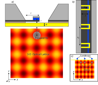
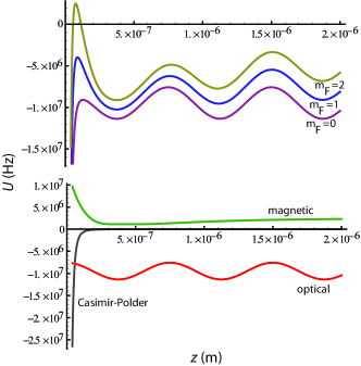
The proposed experimental setup is shown in Fig. 1. The cantilevers have dimensions m, m, and m and are separated from the 3-dimensional atomic optical lattice by a nm thin mirror membrane coated with nm Pt. The atoms are trapped in a 2-d array at distance = nm below the surface. We henceforth consider a one-dimensional lattice of atoms and cantilevers in the direction. In principle many such arrays can be used in parallel to form a two-dimensional lattice. The cantilevers carry a rectangular nano-magnet with strong magnetization A/m, attainable in thin-film magnets, and dimensions nm in the and directions, respectively. We assume a single magnetic domain with moment in the -direction determined by the shape anisotropy. The fundamental-mode resonance frequency of the loaded cantilever is MHz. Additional gradient compensation magnets of dimensions of m nm nm are located on either side of the cantilevers with a -separation of nm to minimize the magnetic gradient at the optical potential minimum. We take an optical lattice with nm, and depth times the photon-recoil energy , corresponding to a trap frequency kHz, and lattice spacing parameter . For definiteness, we consider a configuration where the first vertical anti-node occurs at nm from the surface. An external bias field of T is applied to remove the residual field for a sub-array of three cantilevers and their neighboring compensation magnets, and T is applied to set the desired magnetic field and quantization axis at the trap minimum, corresponding to a Larmor frequency of 1.1 MHz. The total potential is shown in Fig. 2. Tunneling towards the surface can result from the decreased potential well-depth due to the attractive Casimir-Polder interaction casimirpolder . The deep optical lattice serves in part to prevent this loss mechanism, and to further avoid this loss, we operate with only weak magnetic field seeking states, for which the magnetic field from the cantilever tip provides a strong repulsive interaction.
For atomic state manipulation, a local AC voltage can be applied near a cantilever to drive its motion capacitively; the corresponding atomic Rabi frequency is proportional to the amplitude of this motion: for tip magnetic gradient . In order to coherently change internal atomic states, the cantilever can be driven into a large amplitude yielding a sufficiently large Rabi frequency so that the thermal motion has little effect over the period of a Rabi cycle. At distance from the cantilever, , leading to highly localized interactions. In addition, differing mechanical frequencies can be used isolate neighboring sites.
The minimum detectable force due to thermal noise at temperature is where is the cantilever spring constant, is the resonance frequency, is its quality factor, and is the bandwidth of the measurement. For a cantilever separated from a single atom by a distance of 400 nm, the rms force from atomic spin precession is N, becoming detectable in an integration time of 250 ms by a thermal cantilever at mK, with and N/m.
If we set and , and require , we obtain a limit on the phonon occupation number of the cantilever: in order that the force be detected within the cantilever ring-down time , where . Here , and , where is the mass of the Si cantilever and is the mass of the magnet. For example, if , rad/s, and rad/s, this requires of order , so the cantilever must be cooled near its ground state of motion. To facilitate single-atom detection with a thermal cantilever, an adiabatic fast passage protocol similar to that used in magnetic resonance force microscopy could be used rugar1 . A separate sub-lattice of lower frequency cantilevers could be used for this purpose, with atoms being transportable between this detection sub-lattice and the higher resonance frequency control sub-lattice discussed earlier. Here the detection cantilevers can operate at a frequency kHz corresponding to the sweep rate of the adiabatic fast passage, while the cantilevers in the control sub-lattice can still have resonances around MHz as discussed earlier. To distinguish hyperfine levels in this approach, microwave near fields could be used, for example as proposed in Ref. uwavepots .
Optical lattice quantum computation. Single site addressing remains a key challenge for neutral-atom optical-lattice quantum information scenarios. Although focused laser pulses may provide a solution focusedlasers , the cantilever approach is not limited by optical diffraction. As an example, we consider the SWAP gate recently realized in Ref. xchg . The setup consists of a two-dimensional optical lattice that can be transformed into double-wells. The internal qubit states used in the experiment are the and sublevels of the hyperfine ground state manifold of 87Rb. Here a vector light-shift provides an effective magnetic field that allows RF addressing of a sublattice to prepare and toggle these internal states. If the optical lattice can be formed near a surface with a lattice array of cantilevers underneath such as that described in this work, rather than using a global RF source for state preparation, individual driven magnetic cantilevers could be used, adding the capability of single-site state control. Cantilever arrays may be generally useful for single qubit operations in cluster-state quantum computation bloch1 .
Quantum gates and entanglement. We now assume that the fundamental cantilever vibrational mode can be cooled to its ground state and that the measurement imprecision and back-action are sufficiently small that the zero-point cantilever motion can be detected, for example optically or capacitively from the reverse side of the membrane. We consider the coupling of the cantilever to a two-level system composed of the 87Rb hyperfine sub-levels and . The Hamiltonian describing this coupled atom-cantilever system is treutlein1 where and we have not explicitly included the potential associated with the optical confinement or motional degrees of freedom of the atoms. The effective single-atom single-phonon Rabi frequency satisfies the strong-coupling condition for the proposed experimental parameters (see Fig. 3).
The controlled-not (CNOT) gate using the coupled atom-cantilever system is analogous to that proposed and demonstrated for trapped ions ciraczoller ; monroe . The qubits consist of the internal atomic spin states and , along with the cantilever vibrational states and corresponding to Fock states of the ground and first excited states, respectively. The atomic internal state is used as an auxiliary state. By adjusting the background magnetic field, the transition frequency between and can be brought into, and out of, resonance with the fundamental mode of the cantilever. The non-linear Zeeman shift in a background magnetic field of 160 T separates from by approximately Hz.
For the gate sequence, first a pulse is applied to the spin-only component of the wave function, using a semiclassical microwave or Raman transition with interaction Hamiltonian for a time and laser phase , resulting in the transformation Then the magnetic field is ramped so that the cantilever resonance frequency matches , and the two are allowed to interact for the duration of a pulse. For the atom in state , if the cantilever is in its ground state, no interaction occurs, while if the cantilever is in the excited state, after the pulse, the state will acquire a minus sign: Finally, a pulse is applied to the spin-only component of the wave function, completing the CNOT operation.
The atoms in the optical lattice can act as ‘slow flying qubits’, and allow selective long-range entanglement between cantilevers in a planar geometry. We assume an initial state . The magnetic field in the trap is brought into resonance with a cantilever at frequency , and the interaction is allowed to occur for the duration of a pulse. The resulting state is the superposition At this point the optical lattice is translated so the atom under consideration is centered over a second cantilever with frequency . The magnetic background field is shifted to bring this cantilever into resonance with the Zeeman transition , and they are allowed to interact for the duration of a pulse. The final state becomes so that the vibrational states of the cantilevers are in an entangled superposition, despite their differing resonant frequencies and relatively large spatial separation.
Noise sources, Loss and Decoherence. We assume a cantilever with at MHz, which has a dissipation rate of Hz. Experimentally, factors as high as have recently been achieved at low temperature for cantilevers with resonance frequencies of order MHz rugarhighQ . The cantilever decoherence time considered alone limits the atom-cantilever CNOT gate fidelity to roughly for a gate operation time ms (for Hz), and is expected to be a dominant source of infidelity.
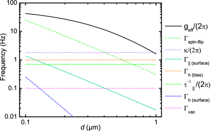
The atomic states involved with the controlled phase gate: and , are susceptible to longitudinal magnetic de-phasing. If is the residual magnetic moment difference between the states in the background magnetic field, the rate of de-phasing can be estimated as for a magnetic field fluctuation at frequencies comparable to or less than the inverse gate operation time sternaharonovimry . For longitudinal magnetic background field fluctuations at the nT level, the de-phasing rate is approximately Hz. The longitudinal spectrum of thermal magnetic field noise at low frequency is estimated varpula ; chiptraplimits as for a metal of thickness at distance above the surface. This leads to a de-phasing rate , where is the noise spectrum of longitudinal magnetic field noise chiptraplimits ; sternaharonovimry . The de-phasing rate for nm of Pt with conductivity ohm-1m-1 at K is shown in Fig. 3. Use of a metal with higher resistivity could be beneficial. Cooling the surface may be helpful provided the metal layer exhibits a sub-linear dependence of resistivity on temperature. Such properties may be attainable by using suitable metallic alloys.
Transverse magnetic field noise at or near the atomic Larmor frequency can result in Zeeman spin-flip transitions with a rate henkel Here the initial and final states and are of the form , , and . For the regime we consider, where the skin-depth at the Larmor frequency ( 100 m at MHz) is much larger than the metal thickness , the spectral density of magnetic field noise can be expressed as varpula The estimated spin-flip rate is shown in Fig. 3. The rates are somewhat slower than that ordinarily obtained for microchip traps below 1 m since the thickness of the metal layer is taken to be only 30 nm. This is permissible since the metal does not need to carry the relatively large electric currents needed for magnetic trapping on atom chips. This feature represents a main advantage of the proposed optical confinement scheme.
The heating rate from the trap ground state to its first excited vibrational state by near-field noise can be estimated for a thin metallic plane as following Ref. chiptraplimits . Fluctuations in the bias fields can result in heating at a rate chiptraplimits where is the spectrum of trap height fluctuations at the trap frequency. For a bias field fluctuation of 0.1 nT, the corresponding heating rate is 1 Hz.
We have identified a possible use for cantilevers in the context of quantum computation with neutral atoms in an optical lattice. Also we have described a scheme for the realization of a controlled-NOT gate in a hybrid atomic-mechanical system. A gate fidelity approaching may be possible with the given experimental parameters. Though significant experimental advances are required to realize the quantum gate or entanglement protocols discussed in this work, they may be possible within a few years. The system may provide a novel testing ground for coherence in macroscopic quantum systems. Higher gate fidelities could be achieved by employing higher resonators or by using tailored materials to improve the near-field magnetic noise environment. For example, factors in the range have been observed harris in different but similar micro-mechanical systems.
We acknowledge helpful discussions with E. Knill, D. Wineland, J. Home, and A. Ludlow. This work of NIST, an agency of the U.S. government, is not subject to copyright. AG acknowledges support from the NRC.
References
- (1) A. Naik et. al., Nature 443 193 (2006).
- (2) J. D. Teufel et. al., Phys. Rev. Lett. 101, 197203 (2008).
- (3) O. Arcizet et. al., Nature 444 71 (2006).
- (4) Claudiu Genes et. al., Phys. Rev. A 77, 033804 (2008).
- (5) J. D. Thompson et. al., Nature 452 72 (2006).
- (6) D. Kleckner and D. Bouwmeester, Nature 444, 75 (2006).
- (7) M. Poggio et. al., Phys. Rev. Lett. 99, 017201 (2007).
- (8) A. Schliesser et. al., Nature Phys. 4 415 (2008).
- (9) W. Marshall et. al., Phys. Rev. Lett. 91 130401 (2003).
- (10) J. Eisert et. al., Phys. Rev. Lett. 93 190402 (2004).
- (11) A.D. Armour, M.P.Blencowe, and K.C.Schwab, Phys. Rev. Lett. 88 148301 (2002).
- (12) A.D. Armour and M.P. Blencowe, New J. Phys. 10, 095004 (2008), A.D. Armour and M.P. Blencowe, New J. Phys. 10, 095005 (2008).
- (13) P. Rabl et. al., arxiv:0806.3606
- (14) Y. Lin et. al., Phys. Rev. Lett. 92 050404 (2004).
- (15) P. Treutlein et. al., Phys. Rev. Lett. 99, 140403 (2007).
- (16) Y. Miroshnychenko et. al. Nature 442 151 (2006), K.D. Nelson et. al., Nature Phys. 3 556 (2007), P. Lee et. al Phys. Rev. Lett. 99, 020402 (2007).
- (17) Y.-J. Wang et. al., Phys. Rev. Lett. 97, 227602 (2006).
- (18) D. Rugar et. al., Nature 430, 329-332 (2004).
- (19) G. K. Brennen et. al., Phys. Rev. Lett. 82 1060 (1999).
- (20) O. Mandel et. al., Nature 425, 937 (2003), I. Bloch, Nature 453, 1016 (2008).
- (21) P. Treutlein et. al., Fortschr. Phys. 54, 702-718 (2006).
- (22) H.B.G. Casimir and P. Polder, Phys. Rev. 73,360 (1948).
- (23) P. Treutlein et. al., Phys. Rev. A 74 022312 (2006).
- (24) J. Beugnon et. al., Nat. Phys. 3 696 (2007).
- (25) M. Anderlini, et. al., Nature 448 452 (2007).
- (26) J.I.Cirac and P.Zoller, Phys. Rev. Lett. 74 4091 (1995).
- (27) C. Monroe et. al., Phys. Rev. Lett. 75 4714 (1995).
- (28) C. Degen, private communication
- (29) A. Stern, Y. Aharonov, and Y. Imry, Phys. Rev. A 41 3436 (1990).
- (30) C. Henkel et. al., Appl. Phys. B (2002).
- (31) T. Varpula, and T. Poutanen, J. Appl. Phys. 55 4015 (1984).
- (32) C. Henkel et. al., Appl. Phys. B 69 379 (1999).