Role of Magnetic Plasmon Resonance in Plasmonic Electromagnetically-induced Transparency
Abstract
We find that the magnetic plasmon resonance plays a vital role in plasmonic electromagnetically-induced transparency (EIT) proposed by Zhang et al. [Phys. Rev. Lett. 101, 047401 (2008)] as well as the localized surface plasmon polaritons. Based on this picture, the plasmonic EIT control through single optical field is suggested in a modified scheme for active plasmonic switching by simply adjusting the incident angle of the optical field. The tunability of plasmonic EIT in this scheme is exhibited sufficiently.
Electromagnetically-induced transparency (EIT) RMP05Flesch is a quantum optical phenomenon to make an absorptive medium transparent to a resonant probe field owing to the destructive quantum interference between two pathways induced by a coupling field. To excite the EIT in a three-level atomic system, the probe and the coupling light must satisfy two-photon resonance, and the Rabi frequency of the coupling light must exceed the effective dephasing rate of medium. Even though the prerequisite of EIT is normally satisfied to most alkali atoms, it is not for most solids owing to a weak oscillator strength and a large dephasing rate. Although the requirement of EIT such as sharp-energy-level transitions with dipole-forbidden ground states looks somewhat critical in application viewpoint, the interest in EIT has been grown up because of the potential applications of optical switching using EIT-enhanced giant Kerr nonlinearity OL96Schmidt in both nonslow-light PRL00Ham and slow-light regimes PRL99Harris . Especially, in an N-type system, where a second control field is added to the EIT scheme, the ultraweak control-field-triggered optical switching PRA08Ham gives a great benefit in nanophotonics as well as quantum information.
Unlike the quantum interference in atomic systems, the coupled components based on different mechanisms can be applied to realize the analogy of EIT in linear classical systems, such as mechanical oscillators, RLC circuits AMP02Alzar , optical resonators PRA01Opatrny , optical dipole antennas PRL08SZhang ; arXiv09HXu , trapped-mode patterns PRL08Papasimakis , split-ring resonators (SRRs) PRL09Tassin , and array of metallic nanoparticles PRB09Yannopapas . As a scheme of EIT-like effect at optical frequencies proposed by Zhang et al. PRL08SZhang and Xu et al. arXiv09HXu , the application of optical dipole antennas is of great interest with the feature of subwavelength, since the half-wavelength scaling breaks down when the localized surface plasmon polaritons (SPPs) play a role in the electromagnetic response PRL07Novotny . In the unit cell, the optical dipole antenna comprising a simple metal strip is termed as the “bright mode” while the other two parallel strips are the “dark mode,” depending on how strong an incident light from free space can be coupled into the plasmonic mode PRL01Stockman . It is generally agreed that the EIT-like effect was ascribed to the coupling of the bright mode with the dark one, the strength of which can be controlled by the spatial separation of two plasmonic modes. However, how the coupling works in the EIT-like effect still remains unknown.
In this Letter, we analyze the underlying physics of the classical version of EIT in a metamaterial, which helps us specifically understand the coupling process of the bright and the dark modes. Based on it, we propose an active plasmonic switching without using the coupling/control fields required in the conventional EIT scheme.
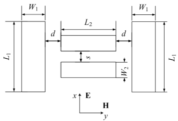
To illustrate the physical picture of the coupling between the bright and the dark modes, we first consider a typical unit cell, as shown in Fig. 1(a), whose geometrical parameters are taken from Ref. PRL08SZhang . The permittivity of metal, , is modeled as silver using the Drude formula, where the plasma frequency and the collision frequency are rad/s and Hz, respectively. The numerical simulation is carried out using a finite-integration package, CST Microwave Studio.
A single metal strip can be electrically polarized by a plane wave, working as an optical dipole antenna and providing the absorption background. In the near zone, the electric dipole fields CE99Jackson approach in the Système International (SI) Units
| (1a) | |||
| (1b) |
where n and p are the unit vector in the direction of propagated field and the electric dipole moment, respectively. There is a phase retardation of the magnetic component with respect to the electric one in the dipole electric fields according to Eq. 1, which differs from those in the radiation zone where they are in phase CE99Jackson ; OPT02Hecht .
Generally speaking, a dark mode cannot be excited efficiently by the external electromagnetic irradiation, since the external electric and magnetic fields are perpendicular and parallel to the two metal strips, respectively. However, we note that the magnetic field from the fields of the dipole optical antenna is normal to the plane of two parallel metal strips, which might stimulate the dark mode based on the magnetic plasmon resonance (MPR) PRB07Sarychev . According to Faraday’s law,
| (2) |
where and are the magnetic field induced by the circular current OL05Shalaev and the permeability of dielectric medium, respectively. the second electric field is excited by the time-dependent magnetic field and the induced one . Integration of Eq. 2 over the dotted-contour in Fig. 1(b) yields the following differential equation PRB07Sarychev :
| (3) |
where , and are the surface current density, the surface impedance ( is the metal permittivity) and the potential drop, respectively. is the distance between points 1 and 4. and are the time derivatives. has the form of
| (4) |
where and are the electric charge in unit area and the medium polarization. The charge conservation law leads to
| (5) |
We substitute into Eq. 3 and take the time derivative on both sides. With the help of Eq. 5, it yields
| (6) |
where is the permittivity of dielectric medium. Parameters and is expressed as:
| (7a) | |||
| and | |||
| (7b) | |||
respectively. Solving Eq. 6, the induced current, , can be obtained under the assumption that is independent on in a finite area and the initial conditions are . Thus, the induced magnetic and electric fields, and , can be written as
| (8a) | |||
| (8b) | |||
| (8c) |
Again, a phase retardation of appears when the electric component is compared with the magnetic one.
Taking into account the former retardation from Eq. 1, the total phase retardation comes to be between two electric fields and , which causes their destructive interference. Consequently, once the localized electric field around the dipole antenna is partially suppressed, the transmission of the incident field is expected to be boosted considerably. This implies that the excitation of MPR contributes to the transmission within an absorption background arising from the localized SPPs. Furthermore, since the interference occurs in the near zone, it is likely to achieve the EIT-like effect even using a single unit, instead of a periodic array, which can make the device more compact.
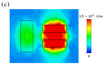
Although the optical destructive interference is totally distinguished from the quantum interference, there is still an analogy of the pathway picture in quantum EIT. The dipole optical antenna is excited by the external electromagnetic irradiation, which is similar to an atomic excitation from a ground state to a excited state. Then, the induced magnetic field by the dipole optical antenna works as a metastable state, which produces the MPR, as implied by Fig. 1(c), and the resultant electric field affects the former dipole electric field owing to the phase difference of . Thus, the superposition of these two electric fields gives rise to the destructive interference as if the transitions between two different pathways render the quantum interference, which provides the EIT-like effect with a vivid classical version.
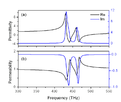
According to the aforementioned analysis, the MPR plays a decisive role in the EIT-like feature at optical frequencies, although it has not been recognized that the localized SPPs and the MPR coexist PRL09Tassin , where the effective permittivity, , and the effective permeability, , are treated separately. The direct way to confirm this coexistence of the localized SPPs and the MPR is to retrieve the effective parameters using the extraction approach in Ref. PRE04XChen . As expected, not only the electric plasmon resonance would be excited, but also the MPR would emerge, as shown in Fig. 2. In addition, the imaginary parts of and are opposite in sign, which does not contradict the fundamental laws in nature PRE03Koschny .
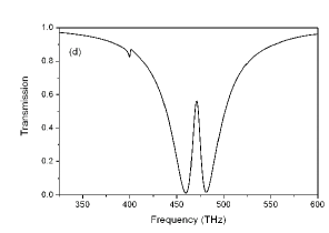
Based on the role of MPR, we present a modified scheme, as shown in Fig. 3, where one more dipole optical antenna is added to form a symmetric structure. Equation 1 tells that the induced magnetic fields, , from the left dipole antenna in Fig. 3 has the same amplitude, but the opposite direction, comparing with that from the right one. These induced magnetic fields lead to the opposite circular currents, which cancel out each other. Thus, the MPR is suppressed, as illustrated in Fig. 4(a), where the magnetic field vanishes between two parallel metal strips in the modified structure, in contrast to that in the typical structure. This means that the EIT-like feature in Fig. 1(c) is destroyed owing to the antisymmetric MPRs, as in Fig. 4(b), like in a resonant N-type four-level atomic system. The antisymmetric MPRs in Fig. 4(a), however, changes if an optical field is irradiated at an oblique angle, where the wavevector, k, varies in the plane. This is because the balance between two induced magnetic fields in Fig. 4(a) is broken by the vertical magnetic component of plane wave, , where and denote the magnetic field of incident field and the incident angle, respectively. Figure 4(c) shows the resultant effect of EIT-like feature, where the magnetic field is considerably localized between the two parallel metal strips like in Fig. 1(c), at an incident angle of 15∘. Correspondingly, the plasmonic EIT is obtained as shown in Fig. 4(d) even with the symmetric design by controlling the incident angle of the optical field.
In conclusion, we propose an active control of the plasmonic EIT in a metamaterial based on MPR, which plays a critical role in it. The generation of MPR, further confirmed by the analytical expressions and the effective permeability, plays as a control field in an N-type atomic system. According to the physical picture we present, the plasmonic EIT is the result of optical destructive interference and is the classical version of atomic EIT. Furthermore, the bright and the dark modes can be either coupled or uncoupled, depending on the angle of incidence in the symmetric structure. Therefore, the active control of plasmonic EIT can be implemented even using only an external field by controlling the incident angle.
This work was supported by MEST/NRF through the Quantum Photonic Science Research Center, Korea.
References
- (1) M. Fleischhauer, A. Imamoglu, and J. P. Marangos, Rev. Mod. Phys. 77, 633 (2005).
- (2) H. Schmidt and A. Imamoglu, Opt. Lett. 21, 1936 (1996).
- (3) B. S. Ham and P. R. Hemmer, Phys. Rev. Lett. 84, 4080 (2000).
- (4) S. E. Harris and L. V. Hau, Phys. Rev. Lett. 82, 4611 (1999).
- (5) B. S. Ham, Phys. Rev. A78, 011808(R) (2008).
- (6) C. L. G. Alzar, M. A. G. Martinez, and P. Nussenzveig, Am. J. Phys. 70, 37 (2002).
- (7) T. Opatrný and D.-G. Welsch, Phys. Rev. A64, 023805 (2001); D. D. Smith, H. Chang, K. A. Fuller, A. T. Rosenberger, and R. W. Boyd, ibid. 69, 063804 (2004); A. Naweed, G. Farca, S. I. Shopova, and A. T. Rosenberger, ibid. 71, 043804 (2005); L. Maleki, A. B. Matsko, A. A. Savchenkov, and V. S. Ilchenko, Opt. Lett. 29, 626 (2004).
- (8) S. Zhang, D. A. Genov, Y. Wang, M. Liu, and X. Zhang, Phys. Rev. Lett. 101, 047401 (2008).
- (9) H. Xu and B. S. Ham, arXiv:0905.3102v4 [quant-ph].
- (10) N. Papasimakis, V. A. Fedotov, N. I. Zheludev, and S. L. Prosvirnin, Phys. Rev. Lett. 101, 253903 (2008); N. Papasimakis, Y. H. Fu, V. A. Fedotov, S. L. Prosvirnin, D. P. Tsai, and N. I. Zheludev, Appl. Phys. Lett. 94, 211902 (2009).
- (11) P. Tassin, L. Zhang, T. Koschny, E. N. Economou, and C. M. Soukoulis, Phys. Rev. Lett. 102, 053901 (2009); Opt. Express 17, 5595 (2009); R. Singh, C. Rockstuhl, F. Lederer, and W. L. Zhang, Phys. Rev. B79, 085111 (2009).
- (12) V. Yannopapas, E. Paspalakis, and N. V. Vitanov, Phys. Rev. B80, 035104 (2009).
- (13) L. Novotny, Phys. Rev. Lett. 98, 266802 (2007).
- (14) M. I. Stockman, S. V. Faleev, and D. J. Bergman, Phys. Rev. Lett. 87, 167401 (2001); T. J. Davis, K. C. Vernon, and D. E. Gómez, Phys. Rev. B79, 155423 (2009).
- (15) J. D. Jackson, Classical Electrodynamics (Wiley, New York, 1999), 3rd ed..
- (16) E. Hecht, Optics (Addison Wesley, San Francisco, 2002), 4th ed..
- (17) A. K. Sarychev, G. Shvets, and V. M. Shalaev, Phys. Rev. B73, 036609 (2006); A. K. Sarychev and G. Tartakovsky, ibid. 75, 085436 (2007).
- (18) V. M. Shalaev, W. Cai, U. K. Chettiar, H.-K. Yuan, A. K. Sarychev, V. P. Drachev, and A. V. Kildishev, Opt. Lett. 30, 3356 (2005); V. D. Lam, J. B. Kim, J. W. Park, S. J. Lee, Y. P. Lee, and J. Y. Rhee, J. Korean Phys. Soc. 53, 1323 (2008).
- (19) X. Chen, T. M. Grzegorczyk, B.-I. Wu, J. Pacheco, and J. A. Kong, Phys. Rev. E70, 016608 (2004).
- (20) T. Koschny, P. Markoš, D. R. Smith, and C. M. Soukoulis, Phys. Rev. E68, 065602(R) (2003); V. A. Markel, ibid. 78, 026608 (2008).
Figure captions
Fig. 1 (color online). (a) Schematic of a typical unit cell consisting of a bright element (single metal strip) and a dark element (two parallel metal strips), whose geometrical parameters , , , , and are 50, 128, 30, 100, 30 and 40 nm, respectively. The thickness of all metal strips is 20 nm. The single metal strip is electrically polarized by the plane wave, working as an optical dipole antenna. (b) Circular current is excited by magnetic field from the fields of optical dipole antenna. (c) Amplitude distribution of the magnetic field at the plasmonic EIT.
Fig. 2 (color online). (a) Real (black curve) and imaginary (blue curve) parts of the effective permittivity , and (b) those of the effective permeability .
Fig. 3. Schematic of a unit cell consisting of two bright elements (metal strips on the left and the right) and a dark element (two parallel metal strips in the middle), whose geometrical parameters are the same as those in Fig. 1 except nm.
Fig. 4 (color online). (a) Amplitude distribution of the magnetic field (at the absorption peak of 471 THz) and (b) transmission spectrum at normal incidence. (c) Amplitude distribution of the magnetic field (at the peak of plasmonic EIT of 471 THz) and (d) transmission spectrum at an incident angle of 15∘ (the reflection plane located in the plane).
![[Uncaptioned image]](/html/0906.4029/assets/x1.png)
![[Uncaptioned image]](/html/0906.4029/assets/x2.png)
![[Uncaptioned image]](/html/0906.4029/assets/x6.png)
![[Uncaptioned image]](/html/0906.4029/assets/x7.png)
![[Uncaptioned image]](/html/0906.4029/assets/x8.png)