Band-gap engineering and ballistic transport in corrugated graphene nanoribbons
Abstract
We calculate the band structure and the conductance of periodic corrugated graphene nanoribbons within the framework of the tight-binding -orbital model. We consider corrugated structures based on host ribbons with armchair and zigzag edges and three different types of corrugations (armchair edges, zigzag edges as well as a rectangular corrugation). We demonstrate that for armchair host ribbons, depending on the type of corrugation, a band gap or low-velocity minibands appear near the charge neutrality point. For higher energies the allowed Bloch state bands become separated by mini-stopbands. By contrast, for corrugated ribbons with the zigzag host, the corrugations introduce neither band gaps nor stopbands (except for the case of the rectangular corrugations). The conductances of finite corrugated ribbons are analyzed on the basis of the corresponding band structures. For a sufficiently large number of corrugations the conductance follows the number of the corresponding propagating Bloch states and shows pronounced oscillations due to the Fabry-Perot interference within the corrugated segments. Finally we demonstrate that edge disorder strongly affects the conductances of corrugated ribbons. Our results indicate that observation of miniband formation in corrugated ribbons would require clean, edge-disorder free samples, especially for the case of the armchair host lattice.
pacs:
73.23.Ad, 73.63.Bd, 73.22.DjI Introduction
One of the most fascinating recent discoveries in condensed matter physics is the fabrication and demonstration of electrical conductance in graphene, - a single sheet of carbon atoms arranged in a honeycomb lattice. Novoselov This discovery has ignited a tremendous interest of the research community not only because of the new exciting physics that the graphene exhibits, but also because of the promise of graphene-based high-speed electronics.Adam
While earlier works on graphene have been focused on bulk samples, recent studies have also addressed material, electronic and transport properties of confined structures such as nanoribons,Chen ; Han07 ; Li nanoconstrictions,Molitor quantum dotsMiao ; Russo ; Stampfer and antidots.Shen The confinement and the patterning of graphene with few nanometer precision is typically achieved by means of electron-beam lithography and etching techniques. Particular attention has been paid to control of the morphology, geometry and stability of the device edges.Jia ; Girit These advances in graphene material technology and device processing make it possible to fabricate ballistic periodic graphene structures with nanometer feature sizes.
Periodic quasi-one-dimensional (quasi-1D) systems defined in conventional two-dimensional electron gas (2DEG) heterostructures such as corrugated channelsKouwenhoven ; Park ; Lent , ballistic one-dimensional supperlatticesUlloa and arrays of quantum dotsShao and antidotsEnsslin ; antidot have been the subject of intense research during the past twenty years. These artificial finite crystal structures show a wealth of phenomena related to the formation of miniband structure and quantum interference. Recently, a periodic structure defined in graphene, - an antidot lattice, - has been studied theoretically by Pedersen et al.Pedersen They demonstrated that the antidot lattice can turn semimetalic graphene into a gapped semiconductor, where the size of the gap can be tuned via the geometry of the lattice. An experimental realization of the antidot array has been recently reported by Shen et al. who observed the commensurability oscillations and Aharonov-Bohm oscillations arising from the artificially imposed lateral potential modulation.Shen
Motivated by these advances in devices processing and fabrication, in the present paper we address the electronic and transport properties of periodic corrugated ballistic nanoribbons. The ballistic nanoribbons represent the fundamental building blocks of graphene-based nanocircuits and/or individual devices. Understanding the factors that affect the electronic and transport properties of graphene nanoribbons and exploring ways to control these properties through periodic corrugations are the central aims of our study.
The paper is organized as follows. In Sec. II we present a model of corrugated graphene nanoribbons and briefly outline the basics of our calculations of the band structure, Bloch states and the conductance based on the recursive Green’s function technique. In Sec. III we calculate the band structures of zigzag and armchair nanoribbons with different corrugations and discuss formation/suppression of the band gap as well as the formation of stopbands. We calculate the conductances of finite corrugated nanoribbons and discuss them on the basis of the corresponding band structures. Finally, we address the effect of the edge disorder on the conductances of realistic corrugated nanoribbons. The main conclusions of our study are presented in Sec. IV.
II Model
We describe a graphene ribbon by the standard tight-binding Hamiltonian on a honeycomb lattice,
| (1) |
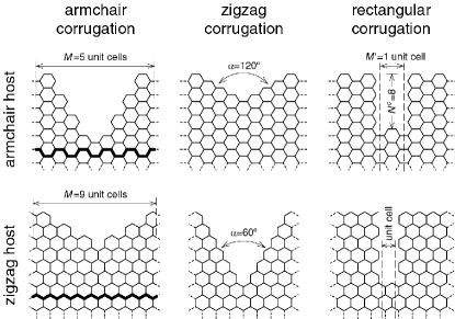
where is the on-site energy, in the following, and eV is the overlap integral between nearest-neighbor atoms. This Hamiltonian is appropriate for graphene with one dangling orbital per carbon atom and is known to describe the band dispersion well at low energies.Reich02 Spin and electron interaction effects are outside of the scope of our study. The effects of corrugations are incorporated by removing carbon atoms and setting appropriate hopping elements to zero. It is assumed that atoms at the edges are attached to two other carbon atoms and passivated by a neutral chemical ligand, such as hydrogen. There are two especially simple classes of corrugations: those with armchair edges and those with zigzag edges. Depending on the edge type and orientation of the host ribbon, an apex angle will equal or , see Fig. 1 and the insets in Figs. 2 and 4. For a given edge, host and , it is possible to change the corrugation size by varying its length . As becomes longer the groove penetrates deeper into the host material until only a single carbon-carbon link persists in the constriction. As a motivation for this choice of corrugation we refer to the recent studiesJia ; Girit demonstrating controlled edge reconstruction with the formation of the sharp stabilized zigzag or armchair edges. For the sake of completeness, we consider also a third type of the corrugation, which has a rectangular shape. Its distinctive feature is presence of the zigzag (armchair) edges joining the armchair (zigzag) edges of the wide and narrow regions.
The Bloch states of the corrugated ribbons are calculated using the Green’s function technique.Igor08 We consider infinitely long graphene ribbons with imposed periodic corrugation in the longitudinal direction. For a translationally invariant system, the solutions of the Schrodinger equation with the Hamiltonian (1) obey the Bloch theorem:
| (2) |
where is the Bloch wave vector and is the Bloch wave function at coordinate . Introducing the Green’s function and using (2), we formulated the eigenproblem as stated in Ref. Igor08, and then solved it numerically. Knowledge of the Bloch states allows one to construct the band diagram, which in turn serves as a basis for analysis of transport properties of the periodically corrugated graphene ribbons.
To analyze the transport properties, we consider periodically repeated corrugations attached to ideal semiinfinite leads. The semiinfinite leads consist of graphene ribbons with the same edge orientation as the host orientation of the corrugated region. As the number of corrugations increases, , we may expect the transport properties of the corrugated channel to be governed by the Bloch states.Lent ; antidot In the opposite limit of , the transport is determined by scattering and localization at the edges of a single constriction.Palacios06
The central quantity in transport calculations is the conductance. In the linear response regime for zero temperature, it is given by the Landauer formula
| (3) |
with being the total transmission coefficient. The transmission coefficient is calculated by the recursive Green’s function method, see Ref. Igor08, for details. Note that knowledge of the Green’s function allows one also to obtain other useful information like wave functions, density of states and currents.Igor08 ; Datta_book
III Results and discussion
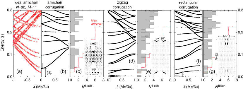
Figures 2(b),(d),(f) show representative band structures of infinite periodic graphene ribbons with different types of corrugations. All of them are created from the armchair host of carbon atom width and unit cell length. These sizes correspond approximately to 10 nm width and 5 nm length. For reference purposes, figure 2(a) presents the band structure of the ideal host armchair ribbon. It has a band gap of as expected for .Dresselhaus96 ; Ezawa06 When the corrugation is imposed, the band diagram undergoes substantial changes. First, for the case of the corrugation with the armchair edge the band gap substantially changes (in the case under consideration it increases by a factor of 1.8), Fig. 2(b). However, for the zigzag edge corrugation, conductive minibands appear near the charge neutrality point , Figs. 2(d),(f). These minibands are very flat indicating their low velocity. Inspection of the wave functions demonstrates that electrons in the low lying minibands are strongly localized to the zigzag edges. Secondly, different bands of Bloch states become separated by gaps or so-called mini-stopbands.Benisty09 Their nature is related to the Bragg reflection due periodic perturbation.Kouwenhoven ; Lent ; Ulloa ; Davies_book Thirdly, the number of propagating Bloch states decreases at most energies in comparison to the ideal ribbon, Figs. 2(c),(e),(g). Fourthly, in many cases avoided crossings of different minibands result in abrupt drops in the number of propagating states in narrow ranges of energy.
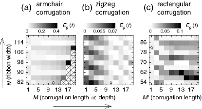
We also performed systematic calculations of the band structures of corrugated ribbons of different width and periodicity . While all of them exhibit similar behavior as outlined above for a representative ribbon of and , particular features of the band structure depend in a sensitive way on the width of the host ribbon and the corrugation periodicity . This is illustrated in Fig. 3 that shows the size of the band gap as a function of the corrugation strength for the armchair host ribbon. In the interval of considered, the host ribbons of width are metallic; all other are semiconducting. For the case of the armchair corrugation, gradually increases as the constrictions narrow (i.e. increases) for most values of , Fig. 3(a). However, for a sequence (corresponding to the semiconducting host ribbons), the band gap slowly decreases and remains rather small (this periodic dependence of the on the ribbon width is clearly seen as horizontal trenches in Fig. 3(a)). This can be explained by the fact that for this sequence the width of the corrugated ribbon in its narrowest part, , shows metallic behavior for all (i.e. the corresponding uniform ribbon of constant width is metallicDresselhaus96 ; Ezawa06 ; note that is odd in Fig. 3(a)), while for all other , the minimal width corresponds to the semiconducting behavior. For the case of zigzag corrugation, the dependence of on the corrugation strength exhibits the opposite trend, Fig. 3(b). We attribute this to the nature of zigzag edges, which favor electron propagation at low energy. Thus for zigzag corrugations the gap tends to be larger for small , for which the zigzag corrugations are interrupted most often by armchair ”defects“ that occur at each apex of the corrugated structure for zigzag corrugation of the armchair host as can be seen in Fig. 1. The rectangular corrugation has many similarities with the armchair case, though electron interference at sharp corners becomes much more important. If the constriction is long enough, substantial band gaps might develop.
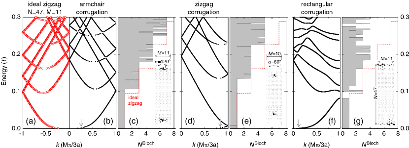
Let us now consider the case of the zigzag orientation of the host ribbon, Fig. 4. The zigzag edges of graphene ribbons are known to accommodate exponentially localized edge states.Dresselhaus96 Independent of the width, zigzag ribbons are metallic with a zero band gap. None of the corrugation types changes this feature and the ribbon stays metallic unless the constrictions are a few atoms wide. As the corrugation deepens into host material, the locations where the electron wave functions are localized shift accordingly, see insets in Figs. 4(c),(e). Robust metallic behavior is also related to a peculiar current density distribution, which is mainly concentrated along the center of the ribbon.Palacios06 ; Nikolic07 Substantial mini-stopbands were found to de- velop for the rectangular corrugation only, Figs. 4(f),(g). (Though there are extremely narrow stopbands in Figs. 4(b)-(e), they are two orders of magnitude narrower and thus unlikely to be observed experimentally.) Because of the abrupt change of the edge configurations electrons stay localized near the edges of the wide regions in this case, see inset in Fig. 4(g).
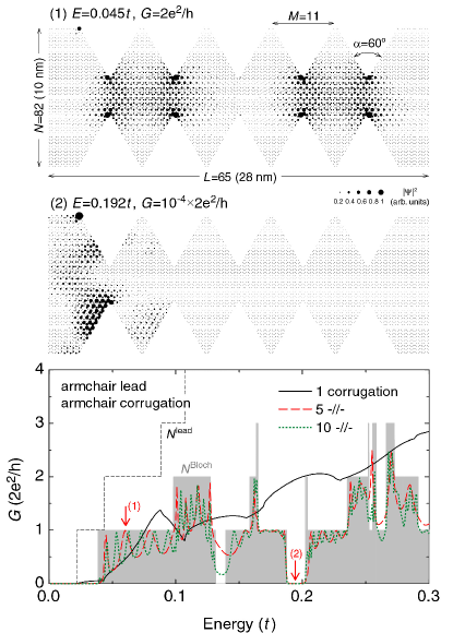
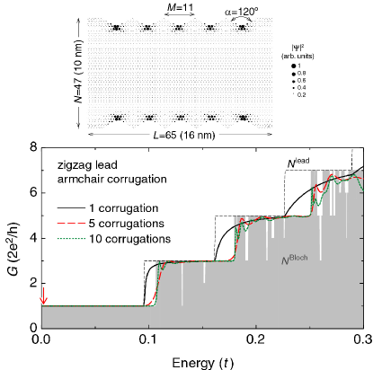
Let us now turn to the transport properties of the corrugated ribbons and the relation to the Bloch states. Figures 5 and 6 show the conductance as a function of the Fermi energy for different number of the corrugations. We build up the central scattering region by connecting the corrugations in series and adding semiinfinite ribbons, that play the role of ideal leads, to both ends. The latter has the same edge orientation as the host of the corrugated part, e.g. they are armchair in Fig. 5 and zigzag in Fig. 6. The most striking feature of these figures is the reduction of the conductance relative to that for the corresponding infinite corrugated ribbons which is given by , where is the number of Bloch states at the Fermi energy in the infinite corrugated structure. As the number of corrugations grows the conductance follows more closely. The strong oscillations observed in Fig. 5 are caused by the Fabry-Perot interference of electron waves inside the scattering region, see the topmost inset for the wave function modulus. If the energy of the incident electron falls into the stop-miniband the conductance may be suppressed by many orders of magnitude due to destructive interference as is seen at energies near in the lower panel of Fig. 5. These features in the conductance of the corrugated ribbons are very similar to those of quasi-1D periodic systems defined in conventional 2DEG heterostructures.Kouwenhoven ; Lent ; Ulloa ; antidot . As is seen in Fig. 6, the electron states existing in the zizgag ribbons have peculiar properties making them relatively immune to the corrugations: the conductance deviates very little from . The wave functions effectively round the grooves and enhanced localization of becomes pronounced at the apexes, Fig. 6. This behavior resembles somewhat that of the edge states in the quantum Hall regime.
Note that our single-particle conductance calculations do not account for charging (Coulomb blockade) effects. However, inspection of the wave function in the corrugated ribbons for the zigzag host near the charge neutrality point (and the corresponding Bloch states) indicates that charging effects may dominate the conductance in this regime. Indeed, because of the strong electron localization near its apexes, the corrugated ribbon effectively behaves as an array of weakly coupled quantum dots, see Figs. 4, 6. This behavior is also reflected in a very low group velocity of the corresponding energy bands. Thus, the corrugated ribbon with the zigzag host is expected to effectively function as an array of weakly coupled quantum dots, even though the corrugations can be relatively small in comparison to the ribbon’s width.
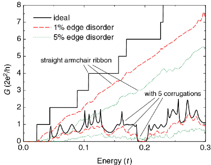
It is well known that the disorder inevitably present in realistic devices has a marked effect on the conductance.Han07 ; Martin08 Figure 7 shows representative results for both a corrugated ribbon and the straight ribbon of the same size. The disorder is introduced onto the edges only and the host ribbon and corrugations are both armchair. We averaged the conductance over ten realizations of the disorder in order to reduce fluctuations and facilitate visualization of the results. The edge defects act as randomly positioned short-range scatterers and induce strong backscattering. It leads to Anderson localization with substantial transport gaps opened for narrow ribbons.Han07 ; Martin08 ; Lewenkopf Even 1% of defects is enough to destroy conductance quantization for the straight ribbon and the Fabry-Perot oscillations for the case of the corrugated ribbon, Fig. 7. The stopbands are smeared already for 5% edge disorder, which indicates that the observation of the miniband formation in the armchair-host corrugated ribbons would require extra-clean, edge-disorder free samples. Note that we also performed calculations for disordered ribbons with the zigzag host. As expected, they showed behavior similar to that shown in Fig. 7 though the defect concentrations producing similar effects on the conductance are significantly larger.
IV Conclusions
We studied the electronic and transport properties of periodic corrugated graphene nanoribbons within the standard -orbital tight-binding model. We considered both armchair and zigzag underlying host ribbons and three different types of corrugation defined by grooves with armchair edges, zigzag edges as well as a rectangular corrugation. We calculated the dispersion relations and Bloch states for corrugated ribbons, and demonstrated that they exhibit different features depending on topology of the host ribbon (i.e. armchair or zigzag). For the armchair host, depending on the type of corrugation, a band gap or low-velocity minibands appear near the charge neutrality point . For higher energies bands of Bloch states become separated by mini-stopbands. By contrast, for corrugated ribbons with the zigzag host, the corrugations introduce neither a band gap nor substantial stopbands (except for the case of the rectangular corrugations).
We calculated the conductance of graphene ribbons with finite numbers of corrugations . As expected, for sufficiently large the conductance follows the number of the corresponding propagating Bloch states and shows pronounced oscillations due to the Fabry-Perot interference within the corrugated region. We also argue that for low electron energies the corrugated ribbon with the zigzag host is expected to effectively function as arrays of weakly coupled quantum dots with the conductance dominated by the single-electron charging effects, even though the corrugations can be relatively small in comparison to the ribbon’s width.
We also demonstrated that as in the case of uncorrugated ribbons, edge disorder strongly affects the conductance of the corrugated ribbons. Our results indicate that observation of miniband formation in corrugated ribbons would require extra-clean edge-disorder free samples, especially for the case of the armchair host lattice.
Finally, we hope that our study will motivate further experimental investigation of periodically corrugated graphene nanoribbons.
Acknowledgements.
This work was supported by NSERC and The Canadian Institute for Advanced Research. I.V.Z. acknowledge financial support from the Swedish Research Council (VR).References
- (1) K. S. Novoselov, A. K. Geim, S. V. Morozov, D. Jiang, Y. Zhang, S. V. Dubonos, I. V. Grigorieva, and A. A. Firsov, Science 306, 666 (2004).
- (2) S. Adam, E. H. Hwang, V. Galitski, and S. Das Sarma, Proc. Natl. Acad. Sci. U.S.A. 104, 18392 (2007).
- (3) Z. Chen, Y.-M. Lin, M. J. Rooks, and P. Avouris, Physica E (Amsterdam) 40, 228 (2007).
- (4) M. Y. Han, B. Özyilmaz, Y. Zhang, and P. Kim, Phys. Rev. Lett. 98, 206805 (2007).
- (5) X. Li, X. Wang, L. Zhang, S. Lee, and H. Dai, Science 319, 1229 (2008).
- (6) F. Molitor, A. Jacobsen, C. Stampfer, J. Güttinger, T. Ihn, and K. Ensslin, Phys. Rev. B 79, 075426 (2009).
- (7) F. Miao, S. Wijeratne, Y. Zhang, U. C. Coskun, W. Bao, and C. N. Lau, Science 317, 1530 (2007).
- (8) S. Russo, J. B. Oostinga, D. Wehenkel, H. B. Heersche, S. S. Sobhani, L. M. K. Vandersypen, and A. F. Morpurgo, Phys. Rev. B 77, 085413 (2008).
- (9) C. Stampfer, J. Güttinger, S. Hellmüller, F. Molitor, K. Ensslin, and T. Ihn, Phys. Rev. Lett. 102, 056403 (2009).
- (10) T. Shen, Y. Q. Wu, M. A. Capano, L. P. Rokhinson, L. W. Engel, and P. D. Ye, Appl. Phys. Lett. 93, 122102 (2008).
- (11) X. Jia, M. Hofmann, V. Meunier, B. G. Sumpter, J. Campos-Delgado, J. M. Romo-Herrera, H. Son, Y.-P. Hsieh, A. Reina, J. Kong, M. Terrones, M. S. Dresselhaus, Science 323, 1701 (2009).
- (12) Ç. Ö. Girit, J. C. Meyer, R. Erni, M. D. Rossell, C. Kisielowski, Li Yang, Ch.-H. Park, M. F. Crommie, M. L. Cohen, S. G. Louie, and A. Zettl, Science 323, 1705 (2009).
- (13) L. P. Kouwenhoven, F. W. J. Hekking, B. J. van Wees, C. J. P. M. Harmans, C. E. Timmering, and C. T. Foxon, Phys. Rev. Lett. 65, 361 (1990).
- (14) M. Leng and C. S. Lent, Phys. Rev. Lett. 71, 137 (1993).
- (15) K. W. Park, S. Lee, M. Shin, J. S. Yuk, El-H. Lee, and H. C. Kwon, Phys. Rev. B 58, 3557 (1998).
- (16) S. E. Ulloa, E. Castaño, and G. Kirczenow, Phys. Rev. B 41, 12350 (1990).
- (17) Zhi-an Shao, W. Porod, and C. S. Lent, Phys. Rev. B 49, 7453 (1994).
- (18) R. Schuster, K. Ensslin, J. P. Kotthaus, M. Holland, and C. Stanley, Phys. Rev. B 47, 6843 (1993).
- (19) I. V. Zozoulenko, F. A. Maaø, and E. H. Hauge, Phys. Rev. B 53, 7975 (1996); ibid., 53, 7987 (1996).
- (20) T. G. Pedersen, C. Flindt, J. Pedersen, N. A. Mortensen, A. P. Jauho, and K. Pedersen, Phys. Rev. Lett. 100, 136804 (2008).
- (21) S. Reich, J. Maultzsch, C. Thomsen, and P. Ordejón, Phys. Rev. B 66, 035412 (2002).
- (22) Hengyi Xu, T. Heinzel, M. Evaldsson, and I. V. Zozoulenko, Phys. Rev. B 77, 245401 (2008).
- (23) F. Muñoz-Rojas, D. Jacob, J. Fernández-Rossier, and J. J. Palacios, Phys. Rev. B 74, 195417 (2006).
- (24) S. Datta, Electronic Transport in Mesoscopic Systems, (Cambridge University Press, Cambridge, 1997).
- (25) K. Nakada, M. Fujita, G. Dresselhaus and M. S. Dresselhaus, Phys. Rev. B 54, 17954 (1996).
- (26) M. Ezawa, Phys. Rev. B 73, 045432 (2006).
- (27) H. Benisty, Phys. Rev. B 79, 155409 (2009).
- (28) J. Davies, The Physics of Low-Dimensional Semiconductors, (Cambridge University Press, Cambridge, 1998).
- (29) L. P. Zarbo and B. K. Nikolić, EPL 80 47001 (2007).
- (30) M. Evaldsson, I. V. Zozoulenko, Hengyi Xu and T. Heinzel, Phys. Rev. B 78, 161407(R) (2008).
- (31) E. R. Mucciolo, A. H. Castro Neto, and C. H. Lewenkopf, Phys. Rev. B 79, 075407 (2009).