High quality GeV proton beams from a density-modulated foil target
Abstract
We study proton acceleration from a foil target with a transversely varying density using multi-dimensional Particle-in-Cell (PIC) simulations. In order to reduce electron heating and deformation of the target, circularly polarized Gaussian laser pulses at intensities of the order of are used. It is shown that when the target density distribution fits that of the laser intensity profile, protons accelerated from the center part of the target have quasi-monoenergetic spectra and are well collimated. In our two-dimensional PIC simulations, the final peak energy can be up to 1.4 GeV with the full-width of half maximum divergence cone of less than . We observe highly efficient energy conversion from the laser to the protons in the simulations.
I INTRODUCTION
Plasma-based particle acceleration has recently demonstrated an impressive progress. Monoenergetic electron beams with up to GeV energy have already been observed in recent experiments (Malka et al., 2002; Leemans et al., 2006). Energetic ion bunches, especially monoenergetic proton beams, have also been obtained in some laboratories (Schwoerer et al., 2006; Fuchs et al., 2006). It is believed that Target Normal Sheath Acceleration (TNSA) (Wilks et al, 2001) is a dominant proton acceleration mechanism when the laser intensity is below some level. However, up to now the energy of ion beams in the ”TNSA” regime is only about a few tens MeV with a low energy conversion efficiency (), which is insufficient for most of the envisioned practical application, such as, e.g. the tumor therapy (Bulanov et al., 2002) and proton imaging (Borghesi et al., 2003). In the past few years, numerous experimental and theoretical studies (Pegoraro et al., 2004; Yin et al., 2006; Nickles et al., 2007; Flippo et al., 2007; Ma et al., 2009; Yu et al., 2009) have been devoted to improving the beam quality. Recently, a new ion acceleration mechanism, Radiation Pressure Acceleration (RPA) (Robinson et al., 2008) has attracted a lot of attention due to its potential to directly transfer the momentum of the laser light to the thin target as a whole. A complete switch from the TNSA to the RPA regime occurs at a laser intensity of (Robinson et al., 2008) for a circularly polarized (CP) laser pulse, which opens a new roadmap to high quality ion acceleration.
In the ”TNSA” regime, a linearly polarized (LP) laser pulse is usually employed due to its superiority in producing hot electrons. Instead, a CP laser pulse with a high peak intensity is more efficient in the generation of quasi-monoenergetic proton beams (Zhang et al., 2007; Yan et al., 2008). It is because of the absence of the oscillating component in the ponderomotive force described below:
| (1) |
where , and are electron static mass, electron charge and laser frequency, respectively. is the relativistic factor and is the laser electric field component. The oscillating part in the ponderomotive force of the LP laser pulse, , can excite a strong oscillation of the electrons. As a result, much more hot electrons are produced, which are essential for the TNSA mechanism. However, for a CP laser pulse, the ponderomotive force has no such a term, but only the time average or zero-frequency component. The strong force directly pushes the electrons inwards the target and forms strong electric fields behind the laser front (Chen et al., 2008). Choosing the appropriate laser and target parameters, one can expect that quasi-monoenergetic proton beams can be produced by these fields (Chen et al., 2009).
To describe the CP laser interaction with an ultra-thin foil, we assume that the force applies to the whole target and that the foil still stays intact during the full laser interaction time. As a result, the target is pushed forward as a whole. Using a simple 1D analytical model, we obtain for the target velocity the following equation (Robinson et al., 2008):
| (2) |
where , and are ion mass, plasma density and target thickness, respectively. is the target velocity normalized by light speed and is the laser electric field component. From the formula, we can see that the acceleration structure is dependent on two factors: target parameters () and laser transverse profile (). For a usual uniform density flat target (UFT) irradiated by a Gaussian laser pulse, the acceleration structure will be soon destroyed due to the target deformation. It is because different parts of the target has experienced different acceleration forces. In order to avoid the target deformation, Chen et al. proposed a shaped foil target (SFT) with an transversely varying thickness (Chen et al., 2009). PIC simulations show that the scheme can suppress both the target deformation and heating efficiently.
In this paper, we suggest an alternative method to produce the high quality proton beams. In our case, the initial foil target is a flat one, but the transverse plasma density follows a Gaussian distribution to match the laser intensity profile. A CP laser pulse is employed and is normally incident on this density-modulated foil target (DMFT). 2D and 3D simulations have been performed, which show that protons from the center part of the target can be accelerated monoenergetically and are well collimated in the forward direction. In our simulations, we observe the final peak energy as high as 1.4 GeV with the full-width of half maximum divergence cone of less than .
II PIC SIMULATIONS AND DISCUSSIONS
We first present a 2D simulation of the scenario using the fully electromagnetic PIC code VLPL (Virtual Laser Plasma Laboratory) (Pukhov, 1999). The simulation box is long and wide ( is the wavelength), which consists of cells, and contains more than macroparticles. The foil target is initially located between and . A CP laser pulse with a Gaussian profile in space and a trapezoidal profile (linear growth - plateau - linear decrease) in time is normally incident on the foil target:
| (3) |
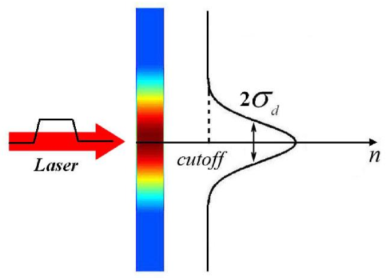
where is the laser intensity normalized by , is the focal spot radius, is the laser cycle. The initial plasma density follows a transverse Gaussian distribution to match the laser intensity profile, as shown in Fig.1. The profile of the modulated density is defined by . The maximal density is while the cutoff is , where is the critical density. The transverse boundary conditions are periodic, while both the front and back boundaries absorb outgoing radiation and particles (Pukhov, 2001). Considering the plasma expansion into vacuum, we provide an appropriate vacuum gap (longer than 42) between the target and the right boundary.
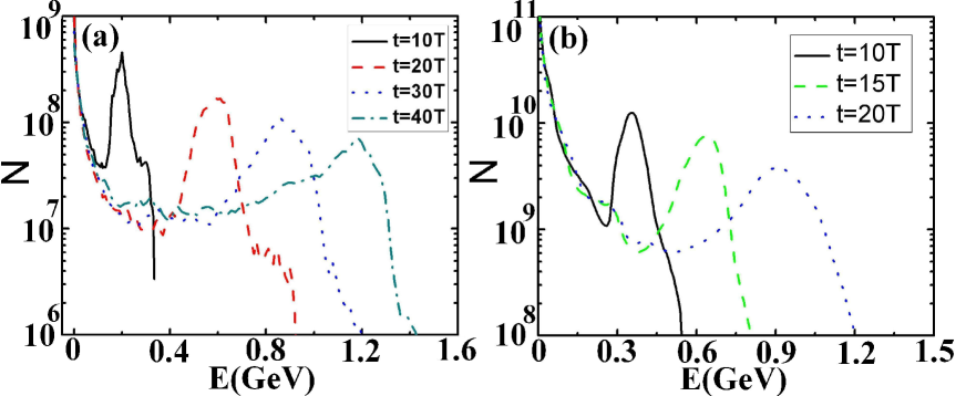
Fig. 2 (a) shows the proton energy spectra at and . Here, the leading edge of the laser pulse reaches the target at about . A clear quasi-monoenergetic peak can be seen in each spectrum. At an early time, , the peak energy is about 200 MeV with a very narrow energy spread. As time goes on, the proton energy increases. At the time , the peak is still very clear although the spectrum shows a relatively wide energy spread. By this time, the peak energy is up to 1.2GeV and contains protons while the cutoff energy is about 1.5GeV. The number of the protons within the energy range 0.8 GeV1.3 GeV is . The monoenergetic peak is accelerated up to 1.4 GeV with the full-width of half maximum divergence cone of less than at the time (165fs).
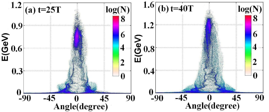
The proton energy as a function of the divergency angle is shown in Fig. 3. It is easy to see from both of the frames that there exists a bunch of protons with a relatively high energy and a low divergency. At , the clump is composed of protons within the energy range 0.65 GeV0.85GeV. However, at a later time , the same protons are shifted to the energy range 0.8 GeV1.3 GeV. The average divergency angle for all these high quality protons is about at and at . Here, the average divergency is calculated as following:
| (4) |
where is the total numbers of the high quality protons, and are the momentum component in and direction, respectively.
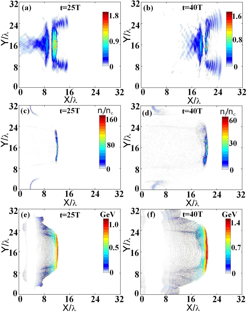
Fig. 4 presents snapshots of the laser intensity and proton acceleration at and . Because of the lower density at the target wing, the ultra-intense laser pulse can easily penetrate it and then propagate into the vacuum behind the target. On the contrary, the center part of the target in the range between to is directly pushed forward by the strong ponderomotive force . As a result, the laser intensity shows a clear inverted cone distribution, as shown in Fig. 4(a) and 4(b). It is this inverse cone that keeps the clump together. According to the formula (2), the protons from the center part will experience a uniform acceleration so that a good acceleration structure survives for a long time, as plotted in Fig. 4(c) and 4(d). Our simulation results qualitatively agree with the above 1D analytical model. Additionally, we also record the proton energy distribution in the space, see Fig. 4(e) and 4(f). By comparing the density distributions, one can easily observe the high quality proton clump mentioned above. The ”radius” of the clump is about at and at , which is approximately equal to the laser focus.
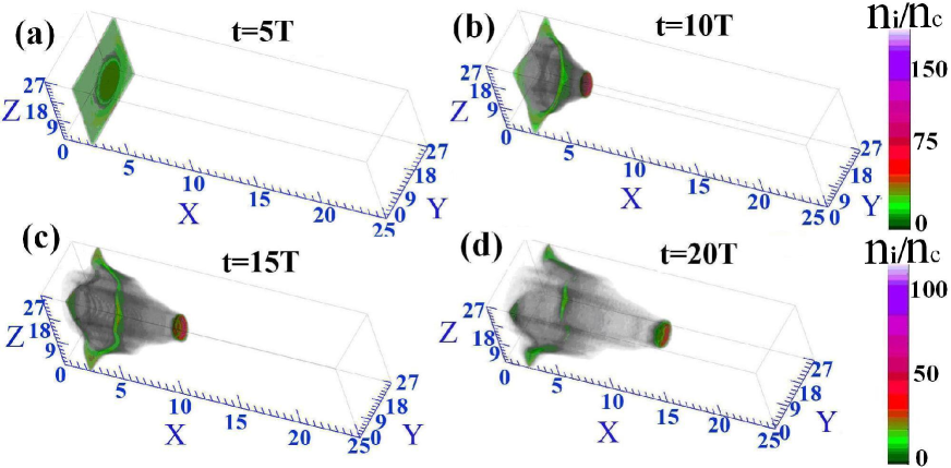
3D PIC simulations have also been performed to check the proton acceleration. Here, both of the shape of the DMFT and the laser profile are the same except the initial target position and . In the 2D case, the target is located at with while in the 3D case they are and , respectively. The pulse duration in the 3D simulations is , which corresponds to a trapezoidal profile 1T–5T–1T. To reduce the computational time, the full simulation box has a size sampled by a grid of cells. Fig. 2(b) shows the proton energy spectra at , and . An obvious energy peak can be observed there. At t=20T, the spectrum shows a peak with the energy of 0.9 GeV corresponding to protons. The total number of the protons with an energy larger than 0.6 GeV is about , which contains a total energy of . The energy conversion efficiency from the laser pulse to these protons is up to 27.1%, which is much higher than that obtained in most other mechanism regimes.
Fig. 5 presents the spatial density distribution of the protons. We can see that the target can keep a good acceleration structure. The simulations confirm the results in the above 2D simulations. Additionally, we also observe the expected proton clump behind the target in the 3D simulations, as shown in Fig. 5(b)–(e). The radius of the clump is about , which is smaller than the laser focus. It may be due to the easier dispersion of the protons in the 3D condition. In fact, the size of the clump depends on the cutoff density, laser focus as well as . When is matched with the laser focus, for a lower cutoff density more protons from the wing target will be uniformly accelerated, which leads to a wider clump radius. On the contrary, these wing protons experienced inhomogeneous forces and would be filtered by the laser pulse. As a preliminary estimation, the optimal cutoff density is half of the maximum, that is in our case.
III COMPARISON OF THE BEAM QUALITY WITH OTHER TARGET PROFILES
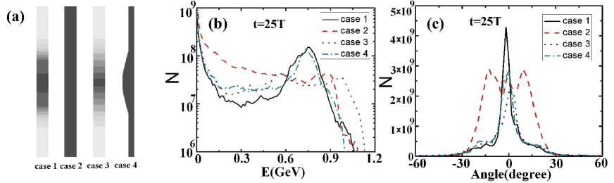
We compare our target with some other profiles, as shown in Fig. 6(a). Among them, the case 2 is just the usual flat foil target (UFT) with the density of , while case 3 is another specially-organized foil target with a density of the transverse linear distribution. Both of the maximal density and cutoff density in the cases 1 and 3 are the same. Case 4 is the SFT presented by Chen et al. (Chen et al., 2009), where the foil thickness is matched to the laser intensity profile. For the convenience of comparison, here the SFT is made with a matched profile (corresponding to a cutoff thickness of ) so that the whole target contains the same number of protons as that in our case. All these targets are located at the same position with the same thickness (for the SFT, it is the maximal thickness) and are irradiated by the same CP laser pulses. In order to save the computational time, we only perform 2D PIC simulations.
Fig. 6(b) presents the spectra of all the protons from the target at . Obviously, only the spectra in the cases 1 and 4 show a quasi-monoenergetic peak structure. That is because the both targets employ a Gaussian profile to match the laser profile, which leads to the uniform acceleration of the target as a whole. In the UFT case, the acceleration structure is destroyed very soon and the spectrum shows an exponential decay. In the case 3 we do observe formation of an inverse cone in the laser intensity behind the target. Yet, different parts of the target experience different acceleration, because the target profile is not matched with that of the laser. Due to the transverse linear distribution of the density, the energy spectrum is not an exponential one, but rather shows a nearly flat distribution. When we compare the DMFT case (the case 1) with the SFT case (the case 4), we mention that there is almost no difference for the distribution of the high energy protons except that, in our case, the number of low energy protons is reduced and more energy is focused on the clump mentioned above. Finally, the energy conversion efficiency from the laser pulse to the high quality protons is highly enhanced.
Finally, we compare the divergence angle for these cases, as shown in Fig. 6(c). As expected, both our DMFT case and the SFT can produce a proton beam with a better collimation. On the contrary, the angle distribution for the UFT shows a larger divergency. That is because the electrons in the UFT are easily scattered by the laser and spread into the vacuum. However, in the DMFT case and SFT case, due to the uniform acceleration, all parts of the target are pushed forward as a whole. Then, the protons have a low divergency angle. On the other hand, compared with the SFT, the proton collimation in the DMFT case is much better. The number of protons with the full-width of half maximum divergence cone of less than in the SFT is about , which is only about 80% of that in the DMFT case. This should be attributed to the inverse cone of laser intensity formed behind the DMFT, which keeps the protons together. On the whole, the beam quality in our case is higher than that in the SFT and much better than that in the UFT.
IV CONCLUSIONS
In conclusion, we study proton acceleration from a density-modulated foil target. In order to avoid the deformation of the target, the density follows a transverse Gaussian distribution to match the laser intensity profile. Meanwhile, a CP laser pulse at intensities of is employed to push the target uniformly. Our 2D and 3D simulations demonstrate generation of the high quality proton beams. A proton clump with a higher energy and better collimation is observed behind the target, whose radius is about equal to that of the laser focus in the 2D simulations. The peak energy of the quasi-monoenergetic protons can be up 1.4 GeV. The corresponding full-width of half maximum divergence cone is less than . The energy conversion efficiency can be up to 27.1% in the 3D simulation. By comparison with some other reference targets, such as the UFT and the SFT, both the acceleration structure and the beam quality as well as the energy conversion efficiency in the DMFT case are further improved.
Acknowledgements.
We thank Prof. F.Q.Shao and Dr. Y.Y.MA for their helpful discussions on this subject. This work is supported by the DFG programs GRK1203 and TR18. T.P.Yu thanks the scholarship awarded by China Scholarship Council (CSC NO. 2008611025). M. Chen acknowledges the support by the Alexander von Humboldt Foundation.References
-
(1)
Borghesi, M., Schiavi, A., Campbell, D.H., Haines, M.G.,
Willi, O., MacKinnon, A.J., Patel, P., Galimberti, M
&Gizzi, L.A. (2003). Proton imaging detection of transient electromagnetic fields in laser-plasma interactions. Rev. Scient. Instrum. 74, 1688–1693. -
(2)
Bulanov, S.V.
&Khoroshkov, V.S. (2002). Feasibility of using laser ion accelerators in proton therapy. Plasma Phys. Rep. 28, 453–456. -
(3)
Chen, M., Pukhov, A., Sheng, Z.M.
&Yan, X.Q. (2008). Laser mode effects on the ion acceleration during circularly polarized laser pulse interaction with foil targets. Phys. Plasmas 15, 113103. -
(4)
Chen, M., Pukhov, A., Yu, T.P.
&Sheng, Z.M. (2009). Collimated GeV monoenergetic ion acceleration from a shaped targe irradiated by a circularly polarized laser pulse. arXiv: 0903.3567. -
(5)
Flippo, K., Hegelich, B.M., Albright, B.J., Yin, L., Gautier, D.C.,
Letzring, S., Schollmeier, M., Schreiber, J., Schulze, R.
&Fernández, J. C. (2007). Laser-driven ion accelerators: Spectral control, monoenergetic ions and new acceleration mechanisms. Laser Part. Beams 25, 3–8. -
(6)
Fuchs, J., Antici, P., D
’Humiéres, E., Lefebvre, E., Borghesi, M. Brambrink, E. Cecchetti, C.A. Kaluza, M. Malka, V. Manclossi, M. Meyroneinc, S. Mora, P. Schreiber, J. Toncian, T., Pépin, H.&Audebert, P. (2006). Laser-driven proton scaling laws and new paths towards energy increase. Nat. Phys. 2, 48 54. -
(7)
Leemans W.P., Nagler B., Gonsalves A.J.,
Toth Cs., Nakamura K., Geddes C. G. R., Esarey E., Schroeder C.B.
&Hooker S.M. (2006). GeV electron beams from a centimetre-scale accelerator. Nat. Phys. 2, 696–699. -
(8)
Ma, Y.Y., Sheng, Z.M., Gu, Y.Q., Yu, M.Y., Yin, Y.,
Shao, F.Q., Yu, T.P.
&Chang, W.W. (2009). High-quality MeV protons from laser interaction with umbrellalike cavity target. Phys. Plasma 16, 034502. -
(9)
Malka, V., Fritzler, S., Lefebvre, E., Aleonard, M.-M., Burgy, F.,
Chambaret, J.-P., Chemin, J.-F., Krushelnick, K., Malka, G., Mangles, S.P.D., Najmudin, Z.,
Pittman, M., Rousseau, J.-P., Scheurer, J.-N., Walton, B.
&Dangor, A.E. (2005). Electron acceleration by a wake field forced by an intense ultrashort laser pulse. Science 298, 1596–1600. -
(10)
Nickles, P. V., Ter-Avetisyan, S., Schnürer, M., Sokollik,
T., Sandner, W., Schreiber, Jörg, Hilscher, D., Jahnke, U.,
Andreev, A.
&Tikhonchuk, V. (2007). Review of ultrafast ion acceleration experiments in laser plasma at Max Born Institute. Laser Part. Beams 25, 347–363. -
(11)
Pegoraro, F., Atzeni, S., Borghesi, M., Bulanov, S., Esirkepov, T.,
Honrubia, J., Kato, Y., Khoroshkov, V., Nishihara, K., Tajima, T., Temporal, M.
&Willi, O. (2004). Production of ion beams in high-power laser plasma interactions and their applications. Laser Part. Beams 22, 19–24. - (12) Pukhov, A. (1999). Three-dimensional electromagnetic relativistic particle-in-cell code VLPL (Virtual Laser Plasma Lab). J. Plasma Phys. 61, 425–433.
- (13) Pukhov, A. (2001). Three-dimensional simulations of ion acceleration from a foil irradiated by a short-pulse laser. Phys. Rev. Lett. 86, 3562–3565.
-
(14)
Robinson, A.P.L., Zepf, M., Kar, S., Evans, R.G.
&Bellei, C. (2008). Radiation pressure acceleration of thin foils with circularly polarized laser pulses. NEW J. Phys. 10, 013021. -
(15)
Schwoerer, H., Pfotenhauer, S., Jäckel, O., Amthor,
K.-U., Liesfeld, B., Ziegler, W., Sauerbrey, R., Ledingham, K. W. D.
&Esirkepov, T. (2006). Laser plasma acceleration of quasi-monoenergetic protons from microstructured targets. Nature 439, 445–448. -
(16)
Wilks, S. C., Langdon, A.B., Cowan, T.E., Roth, M., Singh, M., Hatchett, S.,
Key, M. H., Pennington, D., MacKinnon, A.
&Snavely, R.A. (2001). Energetic proton generation in ultra-intense laser-solid interactions. Phys. Plasmas 8, 542–549. -
(17)
Yan, X.Q., Lin, C., Sheng, Z.M., Guo, Z.Y., Liu, B.C., Lu, Y.R., Fang, J.X.
&Chen, J.E. (2008). Generating High-Current Monoenergetic Proton Beams by a Circularly Polarized Laser Pulse in the Phase-Stable Acceleration Regime. Phys. Rev. Lett. 1000, 135003. -
(18)
Yin, L., Albright, B.J., Hegelich, B.M.
&Fernández, J.C. (2006). GeV laser ion acceleration from ultrathin targets: The laser break-out afterburner. Laser Part. Beams 24, 291–298. -
(19)
Yu, T.P., Ma, Y.Y., Chen, M., Shao, F.Q., Yu, M.Y.,
Gu,Y.Q.
&Yin, Y. (2009). Quasimonoenergetic proton beam from ultraintense-laser irradiation of a target with holed backside. Phys. Plasma 16, 033112. -
(20)
Zhang, X.M., Shen, B.F., Li, X.M, Jin, Z.Y.,; Wang,
F.C.
&Wen, M. (2007). Efficient GeV ion generation by ultraintense circularly polarized laser pulse. Phys. Plasmas 14, 123108.
Figure Captions
Fig. 1. Schematic diagram of the DMFT case. The curved line shows
the density distribution along the transverse direction. The dashed
line indicates the cutoff density of the target. defines
the transverse density profile. A CP laser pulse
is incident on the foil target from the left boundary.
Fig. 2. Proton energy spectra for the DMFT case in the 2D
simulations (a) and 3D simulations (b). Here, both of the shape of
the DMFT and the laser profile are the same except the initial target position and .
Fig. 3. Proton energy as a function of the divergency angle for the
DMFT in the 2D simulation at (a) and (b)
.
Fig. 4. Spatial distributions of the laser intensity
for the DMFT case in the 2D simulation at (a) t=25T
and (b) t=40T . Spatial
density distributions of protons for the DMFT case in the 2D simulation at (c) t=25T and (d) t=40T.
Spatial energy distributions of protons for the DMFT case in the 2D
simulation at (e) t=25T and (f) t=40T. The uniformly accelerated
protons with up to GeV energy are observed.
Fig. 5. Spatial density distributions of protons for the DMFT case
in the 3D simulation at , , and . A clear
proton clump formed behind the target can be easily
distinguished from (b), (c) and (e).
Fig. 6. Comparison among different target profiles (a). Here all the laser parameters are the same. For the cases 1 and 3, the density follows a transverse Gaussian distribution and linear distribution, respectively. Both of the maximal density and cutoff density are the same. For the case 2, it is a usual flat target with a uniform density of . For the case 4, the target thickness follows the transverse Gaussian distribution while the density is also uniform (). Proton energy spectra (b) and divergency angle (c) at are shown in the second and third frames.