Enhanced transmission of transverse electric waves through subwavelength slits in a thin metallic film
Abstract
By coating a cover layer with metallization of cut wire array, the transmission of transverse electric waves (TE; the electric field is parallel to the slits) through subwavelength slits in a thin metallic film is significantly enhanced. An 800-fold enhanced transmission is obtained compared to the case without the cut wires. It is demonstrated that a TE incident wave is highly confined by the cut wires due to the excitation of the electric dipole-like resonance, and then effectively squeezed into and through the subwavelength slits.
pacs:
78.66.Bz, 78.20.Ci, 73.20.Mf, 78.67.-nSince the first experimental report of “extraordinary optical transmission” (EOT) through an metallic grating with periodic subwavelength holes Porto , there has been considerable interest in the “enhanced” transmission phenomena of subwavelength apertures in metals, such as one-dimensional (1D) periodic arrays of slits Porto ; Cao , two-dimensional (2D) periodic arrays of cylindrical Ebbesen ; Mart and rectangular (square) holes Molen ; Klein , and a single aperture surrounded by periodic corrugations Takakura ; Moreno ; Vidal . It is worth noting that there are two different transmission mechanisms of subwavelength apertures. Since the subwavelength holes do not support the propagating modes, the transmission of incident waves can only rely on the evanescent tunneling process that can be enhanced by either diffraction or surface wave excitation. As to the subwavelength slits, there is always a propagating waveguide mode with no cutoff frequency Kong for transverse magnetic (TM) waves (i.e., the magnetic field parallel to the slits). Utilizing this guided mode can result to strong transmission of TM waves through the slits Went .
Lots of works on the EOT phenomena of subwavelength slits have been reported in microwave and optical frequencies Bravo ; Lockyear ; Yang . However, most of them have been focused on TM waves. This paper is dedicated to enhance the transmission of TE waves (i.e., the electric field is parallel to the slits) through subwavelength slits in a thin metallic film. Different from TM waves, the transmission of a TE wave through a subwavelength slit has a cut-off frequency Kong , below which no propagating mode exists. By coating a cover layer with a metallization of cut wire array, the transmission of a TE wave through an array of subwavelength slits can be drastically enhanced at a resonant point below the cut-off frequency.
A 1D periodic array of subwavelength slits perforated in an aluminum film is shown in Fig. 1(a). The thickness of the metallic film is , the width of the slits is , and the period of the slit array is (these parameters are chosen to be practical in experiments). By using a Finite-Integration Time Domain algorithm CST , the transmission spectrum of the slit array is calculated and shown by the dashed (red) curve in Fig. 2(a) (where the transmission values are amplified by 50 times to improve the visibility). In calculation, a TE plane wave is normally incident on the structure. Since the considered wavelength ( ) is much larger than the slit width () no propagating mode can be excited by the TE plane wave Kong . So the transmission can only rely on the evanescent tunneling process, and is pretty low () even for such thin metallic film at microwave frequencies.
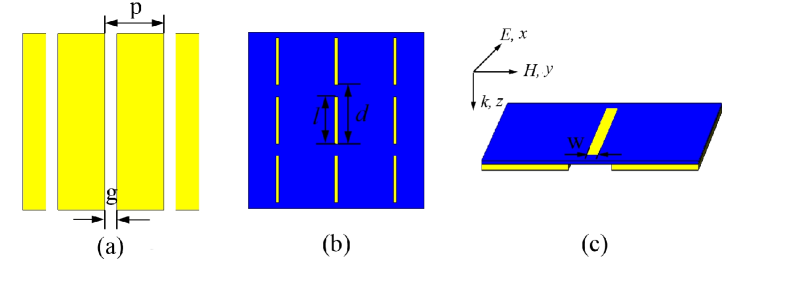
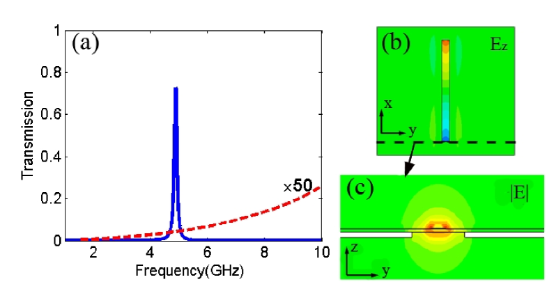
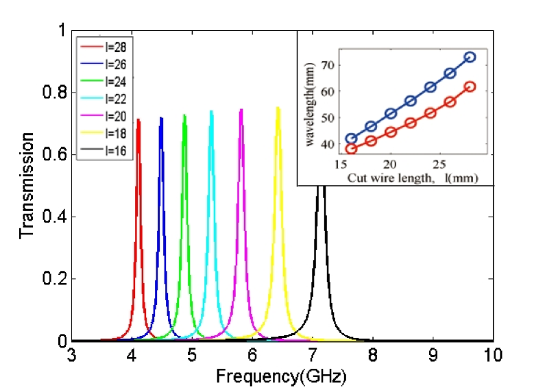
To enhance the transmission of the subwavelength slits, a cover layer which is formed of cut wire array metallized on a dielectric substrate is used, as shown in Fig. 1(b). The metallization was in copper with a thickness of . The cut wires are of length and width . The period of the cut-wire array in the x and y directions are and , respectively. The dielectric substrate is of permittivity and thickness . The unit cell of the composite structure for transmission calculation is shown in Fig. 1(c). As the simulation result represents (see the solid curve in Fig. 2(a)), a resonant transmission peak appears at frequency ( ) with transmissivity of up to , which is about times larger than that in the case without the cover layer. At resonance, the distribution of the z-component electric field on the cut wire is shown in Fig. 2(b), which represents that charges of opposite signs accumulate at the two ends of the broken wire, indicating the excitation of a strong electric dipole-like resonance Zhou on the cut wire. The distribution of the corresponding electric field magnitude on the y-z plane at the side edge of the cut wire is shown in Fig. 2(c), from which one sees that the resonant electric field is highly localized in a subwavelength range around the cut wire. Based on the strong localized electric field near the input apertures of the slits, the incident wave is effectively coupled into evanescent waves, and then squeezed through the subwavelength slits. Consequently, a striking resonant transmission is obtained. To further demonstrate that the drastic transmission improvement is caused by the electric dipole-like resonance of the cut wires, Fig. 3 shows the transmission for different cut-wire length , where varies from to . The resonant frequency of the transmission peak obviously shifts with , while the peak amplitude changes little. The corresponding resonant wavelength of the transmission peak is shown by the blue curve in the inset of Fig. 3 as a function of . For comparison, the resonant wavelength of the fundamental mode (i.e., the electric dipole-like resonant mode) of the cut wires for different is also shown in the inset of Fig. 3 (red curve). The correlation of the two curves indicates that the resonant transmission frequency is dominantly determined by the resonance of the cut wires. The relatively small frequency difference between the two curves is caused by the interaction of the cut wires with the patterned metallic film.
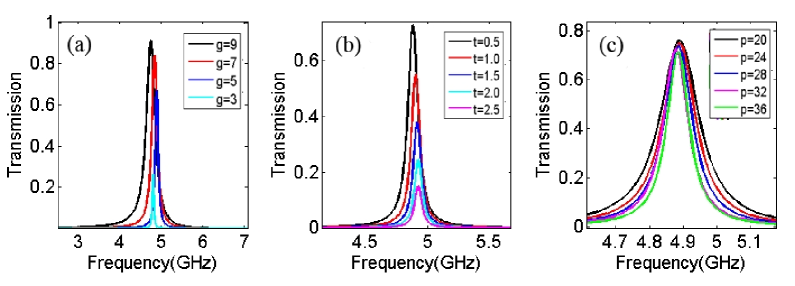
Next, the influence of the geometric parameters of the slit array on the resonant transmission of the composite structure is investigated. Figs. 4(a) and 4(b) show the corresponding transmission when the thickness of the metallic film and the width of the slits are changed, respectively. The other parameters are the same as those used in Fig. 2. The amplitude of the resonant transmission peak rapidly drops with the decrease of and increase of . It is not unexpected that reducing the size of the apertures and thickening the metallic film will reduce the evanescent wave tunneling and diminish the transmission, like the case of surface plasmon enhanced EOT Degiron ; van through the subwavelength hole array. Nevertheless, the current enhanced transmission is not due to surface plasmon, as the incident wave is a TE wave and the structure works at microwave frequencies. In Figs. 4(a) and 4(b), a striking point is that the peak frequency does not obviously shift with the variation of and , because the transmission is based on the evanescent tunneling process and the resonant frequency is determined by the cut wires as discussed in the above. Notably, in the previous works on the EOT phenomena of TE waves Lu ; Crouse through the slit which is need to be wide enough to support propagating modes, the frequency of resonant transmission is sensitive to the geometric parameters of slits, since the EOT is caused by the excitation of cavity modes in the slits. Fig. 4(c) shows the transmission of the composite structure when the period is varied. The transmission peak is not perceptibly changed with the variation of , which indicates that Bloch surface waves Ruan are not contributed to the drastically enhanced transmission
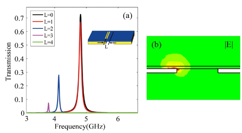
It is also interesting to explore the transmission behavior when the cover layer is laterally displaced relative to the patterned metallic film. The lateral shift is denoted by in the inset of Fig. 5(a). The other parameters are the same as those used in Fig. 2. The transmission for different is shown in Fig. 5(a). When is below , the transmission does not perceptibly change [see the red curve in Fig. 5(a)]. That is to say that the resonant transmission is quite stable for small lateral displacement which could be easily induced by experimental error. As is further increased, the amplitude of the resonant transmission peak rapidly drops. When reaches , no resonant transmission peak is observed as shown by the green line (overlap with the x-axis) in Fig. 5(a). The distribution of the electric field magnitude in Fig. 5(b) can well explain the above behavior. The electric dipole-like resonance is highly localized around the cut wire. When is small, the localized resonant field is blocked little by the metallic film, and the transmission is insignificantly influenced. When becomes large, a part of the localized resonant field is blocked by the metallic film, and the resonant transmission is suppressed since the incident wave can not effectively coupled into the slits. As shown by the above simulation results, this resonant transmission enhancement can be manipulated just by changing the laterally displacement .
In conclusion, we have numerically demonstrated that at microwave frequencies the transmission of TE waves through subwavelength slits in a thin metallic film can be greatly enhanced by assistant cut wires. The electric dipole-like resonance which makes the incident TE wave tightly confined around the cut wires plays a key role in the enhanced transmission mechanism. Although our numerical calculation were carried out at microwave frequencies, the proposed method of transmission enhancement can be easily extended to terahertz frequencies or optical frequencies due to the simplicity of the present structure.
This work is partly supported by the National Basic Research Program (No. 2004CB719801), the National Natural Science Foundations (NNSF) of China under Project No. 60688401 and 60677047.
References
- (1) J. A. Porto, F. J. García-Vidal, and J. B. Pendry, Phys. Rev. Lett. 83, 2845 (1999).
- (2) Q. Cao and P. Lalanne, Phys. Rev. Lett. 88, 057403 (2002).
- (3) T. W. Ebbesen, H. J. Lezec, H. F. Ghaemi, T. Thio, and P. A. Wolff, Nature 391,667 (1998).
- (4) L. Martín-Moreno, F. J. García-Vidal, H. J. Lezec, K. M. Pellerin, T. Thio, J. B. Pendry, and T. W. Ebbesen, Phys. Rev. Lett. 86, 1114 (2001).
- (5) K. L. van der Molen, K. J. Klein. Koerkamp, S. Enoch, F. B. Segerink, N. F. van Hulst, and L. Kuipers, Phys. Rev. B 72, 045421 (2005).
- (6) K. J. Klein. Koerkamp, S. Enoch, F. B. Segerink, N. F. van Hulst, and L. Kuipers, Phys. Rev. Lett. 92, 183901 (2004).
- (7) Y. Takakura, Phys. Rev. Lett. 86, 5601 (2001).
- (8) L. Martín-Moreno, F. J. García-Vidal, H. J. Lezec, A. Degiron, and T. W. Ebbesen, Phys. Rev. Lett. 90, 167401 (2003).
- (9) F. J. García-Vidal, H. J. Lezec, T. W. Ebbesen, and L. Martín-Moreno, Phys. Rev. Lett. 90, 213901 (2003).
- (10) J. A. Kong, Electromagnetic Wave Theory (John Wiley and Sons, New York, 1986).
- (11) H. E. Went, A. P. Hibbins, J. R. Sambles, C. R. Lawrence, and A. P. Crick, Appl. Phys. Lett. 77, 2789 (2000).
- (12) J. Bravo-Abad, L. Martín-Moreno, and F. J. García-Vidal, Phys. Rev. E 69, 026601, (2004).
- (13) M. J. Lockyear, A. P. Hibbins, and J. R. Sambles, Appl. Phys. Lett. 91, 251106 (2007).
- (14) F. Yang and J. R. Sambles, Phys. Rev. Lett. 89, 063901 (2002).
- (15) All the simulations in this paper are performed using software package CST Microwave Studio, CST GmbH, Germany.
- (16) J. Zhou, Th. Koschny, and C. M. Soukoulis, Opt. Express 15, 17881 (2007).
- (17) Y. Lu, M. H. Cho, Y. Lee, and J. Y. Rhee, Appl. Phys. Lett. 93, 061102 (2008).
- (18) D. Crouse, and P. Keshavareddy, Opt. Express 15, 1415 (2006).
- (19) A. Degiron, H. J. Lezec, W. L. Barnes, and T. W. Ebbesen, Appl. Phys. Lett. 81, 4327 (2002).
- (20) K. L. van der Molen, F. B. Segerink, N. F. Van Hulst, and L. Kuipers, Appl. Phys. Lett. 85, 4316 (2004).
- (21) Z. Ruan, and M Qiu, Phys. Rev. Lett. 96, 233901 (2006).