Test of a LYSO matrix with an electron beam between 100 and 500 MeV for KLOE-2
Abstract
The angular coverage extension of the KLOE-2 electromagnetic calorimeter, from a polar angle of 20∘ down to , will increase the multiphoton detection capability of the experiment enhancing the search reach for rare kaon, and prompt decay channels. The basic layout of the calorimeter extension consists of two small barrels of LYSO crystals readout with APD photosensors aiming to achieve a timing resolution between 300 and 500 ps for 20 MeV photons. The first test of a (5.5613) cm3 prototype for such a detector was carried out in april 2009 at the Beam Test Facility of Laboratori Nazionali di Frascati of INFN with an electron beam from 100 to 500 MeV. In the selected energy range, we measured a light yield of 500800 p.e./Mev, an energy resolution which can be parametrized as , a position resolution of 2.8 mm and a timing resolution of 200300 ps.
keywords:
Calorimetry , LYSO , KLOE-2 , timing resolutionPACS:
29.40.Vj, 29.40.Mc1 Introduction
In the last years, a new machine scheme based on the Crab-waist and a large Piwinsky angle has been proposed and tested [1] to improve the reachable luminosity at the Frascati -factory, DANE, an e+e- collider running at the center of mass energy of the resonance. The success of this test motivated the startup of a new experiment, named KLOE-2 [2], which aims to complete the KLOE [3] physics program and perform a new set of interesting measurements. The first running phase will start at the end of 2009 with the goal of collecting 5 fb-1 in one year. For this first run, the modification of the KLOE detector will be minimal with the only introduction of a tagging system. A second phase, for a longer data taking, will require another set of upgrades all concentrated around the beam-pipe consisting of: (i) an inner tracker, IT, based on Cylindrical GEM technology, (ii) a tile calorimeter surrounding the inner quadrupoles , QCALT , and (iii) a calorimeter between the interaction point, IP, and the first inner quadrupole. In the following, we describe the work done to design and test the possibile solution for the latter detector.
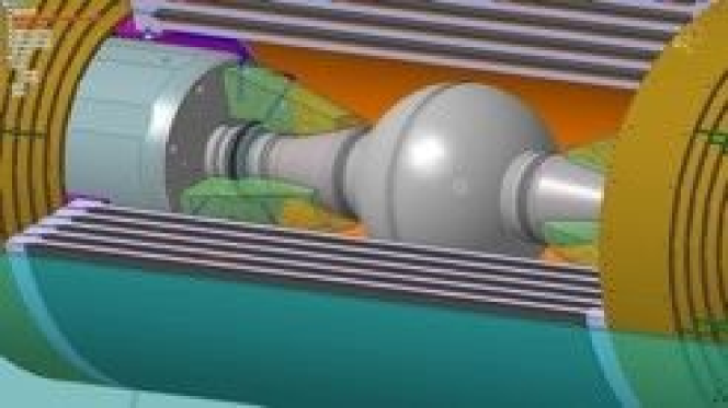
In Fig. 1, we show a zoomed-view of the available region around the IP which can be used to extend the angular coverage of the main electromagnetic calorimeter, today limited at a polar angle of 20∘, with the addition of a new dedicated calorimeter. Assuming to be able to lower the minimum polar angle for photon detection down to 8∘, this will enhance the multiphoton detection capability of the detector for the search of rare decays of kaons, and mesons. As an example, in 2007 the KLOE experiment has measured a BR() [4] in good agreement with O(p4) calculation of Chiral Perturbation Theory but which differs of three standard deviations from the same measurement carried out by the NA48 experiment. The proposed upgrade will allow to improve the S/B ratio of a factor of three thus allowing to solve this puzzle. Other searches or branching ratio determinations, such for instance or , will directly benefit from this extension. The only available area to place a calorimeter lies between the end of the spherical beam pipe, of 10 cm radius, and the first quadrupole, positioned at 30 cm distance from the IP.
2 CCALT: a Crystal Calorimeter with Time
The discussion of the previous section indicates that this calorimeter has to be very dense, with a small value of radiation length, , and Moliere radius, , not hygroscopic and with a large light output to improve photon detection efficiency at low energy (from 20 to 500 MeV). Moreover, the calorimeter has to be extreemely fast in order to allow prompt photon reconstruction in an environment with a large background rate ( 1 5 MHz) of secondary showers generated by off-axis e+, e- coming from intra-bunch scattering (Touschek effect). Preliminary simulation studies indicates the need to reach a time resolution of 300 500 ps for 20 MeV photons.
A suitable solution is offered by a crystal calorimeter with good timing performances, named CCALT. A first detector layout consists of two concentrical barrels of 24 crystals each, with transversal dimensions of 22 cm2 and longitudinal length between 13 and 15 cm. The best crystal choice matching the requirements is provided by the new generation of Cerium doped Lutetium Yttrium Orthosilicate, LYSO, which has and values (1.1 and 2 cm) comparable to the ones (0.9 and 2 cm) of the Lead Tungstanate, PbWO4, with the advantage of a much larger light yield ( 300). On the negative side, LYSO shows a scintillation emission time ( ns) slower than PbWO4 ( ns). However, from the basic scaling law of the timing resolution, , we expect LYSO to be a factor four more performant than PbWO4.
In the final location of the CCALT inside KLOE-2, the presence of an axial magnetic field of 0.52 kGauss forces the usage of silicon based photodetectors. Due to the high photon yield, the readout with APDs is a valid solution since, at the lowest photon energy of 20 MeV, the collected photoelectrons will be around 10.000 which corresponds to 12 pC assuming an average gain of 300 and an amplification stage of , well matching the ADC sensitivity of the KLOE calorimeter (100 fC/count). In the following, we specifically considered only the Hamamatsu S8664-55, which has an active area of 0.50.5 cm2, fast timing characteristics and a quantum efficiency between 65 and 85% in the wavelenght range of interest (390 500 nm) for the LYSO emission spectra.
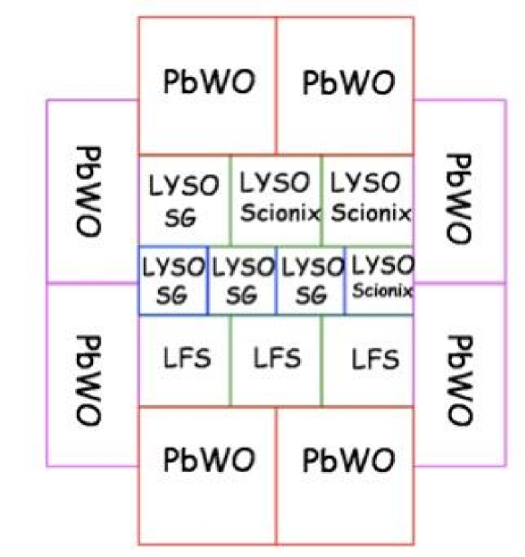
In march 2009, we have built a medium size crystal matrix prototype with transversal radius larger than 2 , longitudinal dimensions being constrained by budget limits to be between 13 and 15 cm (corresponding to 11 12 of longitudinal containment). The prototype consists of an inner matrix of 10 LYSO crystals readout by APD and an outer matrix, for leakage recovery, composed by 8 PbWO4 cristals readout by standard Hamamatsu Bialcali photomultipliers of 1,1/8” diameter. To test the quality of the crystals offered by different vendors, the inner matrix has been assembled in three rows (see Fig. 2) composed (from bottom to top) as follows:
-
1.
3 LFS crystals from Zecotek of 2213 cm3,
-
2.
2 LYSO St.Gobain crystals of 1.51.515 cm3, 1 LYSO St.Gobain + 1 LYSO Scionix crystals of 1.51.513 cm3
-
3.
1 LYSO St.Gobain crystal of 2215 cm3, 2 LYSO Scionix crystals of 2213 cm3.
The LFS from Zecotek is a Luthetium Fine Silicate crystal, with very similar properties to LYSO. Each crystal is wrapped with 100 m of tyvek on the lateral faces, leaving free both the front and end faces, thus allowing to bring calibration light pulses through an external LED and a fast change of the photosensors readout. Each APD is inserted in a PVC mask with the amplifier soldered on its anode and then mecchanically positioned inside a stainless steel box closed by a PVC cap with only the electronic pins coming out for connection to HV and readout cables. An external holder takes the PMs in position for the readout of the outer crystals while allowing to press the boxes containing the APDs. The optical connection of the photosensors with the crystals is done with optical grease. The amplifiers are based on the MAR8A+ chip from Minicircuits, with a gain factor of 25 and a bandwidth of 1 GHz.
3 Test results with electron beams.
We have taken data at the Beam Test Facility, BTF, of LNF for two weeks in april 2009. The matrix was positioned at the center of the beam axis with an area delimited by a cross of two finger BC408 scintillators of cm3 dimensions, . In most of the tests, the fingers were aligned in such a way to define a beam spot of cm2. In front of the fingers it was also present a beam position monitor, BPM, of the BTF group, consisting of sixteen horizontal and vertical scintillator strips readout by two Multi Anode PMs. Each strip is built by three 1 mm diameter scintillating fibers thus providing an accuracy below 1 mm on the beam localization.
We have triggered by using a replica of the spill signal from the Linac adjustable from remote in order to correctly put the signals in time. Prototype signals were splitted and discriminated by means of the standard KLOE calorimeter SDS boards. We acquire data with the KLOE-2 daq system, VME based, reading out KLOE ADC and TDC boards with a sensitivity of 100 fC/count and 50 ps/count respectively.
The BTF beam allows to set the average number of electrons, arriving to the detector by adjusting dedicated collimators. However, we could not lower below 1 for all beam energies and we cleaned the data offline by cutting on pulse height on the f1, f2 counters.
Observing the response of the prototype to single electrons, we realized that the outer matrix was not properly working due to an unexpected optical cross-talk between crystals. This was discovered by pulsing a UV LED (at 380 nm) in the front face of each LYSO crystal to let it scintillate and testing, both at the scope and with a fast data taking, the amount of signal observed on the contiguous crystals. We observe large cross-talk only on the PbWO4 of the outer matrix. We believe this to be due by a cooperation between a light leak through the tyvek and the different amplification gains between PMs and APDs. In the following, we therefore report only results related to the inner matrix.

By using the UV LED, we have first equalized each channel at 10% level by proper HV adjusting. We have then calibrated the calorimeter response of each channel with minimum ionizing particles, m.i.p., crossing the calorimeter hortogonally to the crystal axis. To do this, we have collected cosmic ray runs with a dedicated trigger defined by two plastic scintillators positioned one above and one below the prototype. We get of 5 counts and a m.i.p. peak, , of around 100 counts for the smaller size crystals. The statistical precision on the peak determination is 1 %. The total response of the detector is then defined as:
| (1) |
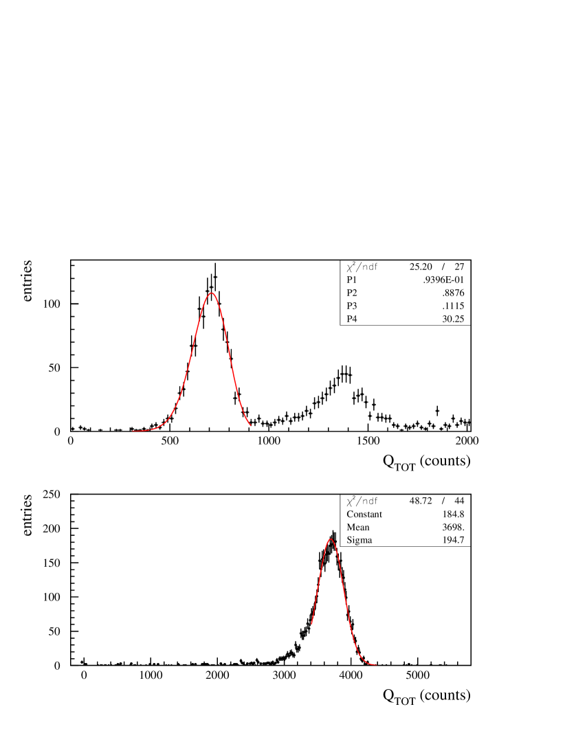
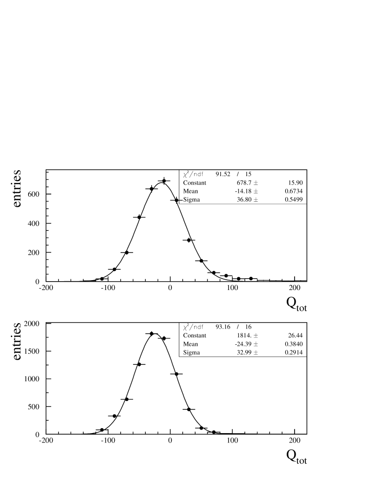
where and are the collected charge and the pedestal of the -th channel, represents an average calibration of all channels in counts and the calibration for the larger crystals is corrected for the different size. In Fig. 3, we show the distribution of for a beam of 100 and 500 MeV respectively after having selected single electron events with a cut on the finger scintillators. A surviving fraction of events with more than 1 electron is still observed in the matrix, expecially at low energies. We have fit the distribution corresponding to one electron either with a simple gaussian, centered around the peak, or with a logarithmic gaussian, logG, function as follows:
| (2) |
where N is a normalization factore, represents the asymmetry, the most probable value of the distribution, and is the resolution.
By performing a linear fit to the distribution of vs , we get a slope of 7.5 0.1 counts/MeV which sets the value to be 16 MeV for a small crystal consistently with an expected energy loss of 10 MeV/cm. At the running voltages of 410 V, the expected APD gain varies between 300-500 from which we estimate the light yield to be between 500 and 800 p.e./MeV.
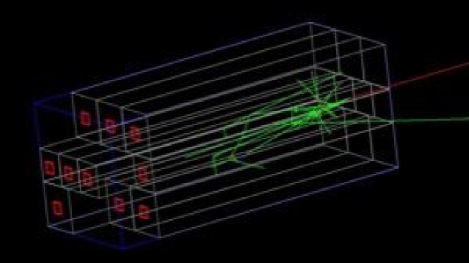
To understand the different terms of the energy dependence of the energy resolution, we are carring out a full simulation of the prototype based on Geant-4. In Fig. 4, we report one example of 100 MeV electron shower as seen from the MC program. We have also simulated the dead space of 100 m of tyvek between crystals and activated the optical transportation of photons. Studies on photoelectron collection efficiency are still underways. This simulation indicates that there is a large leakage term between 5 and 4 % from 100 to 500 MeV.
In Fig. 5, we show the energy dependence of the energy resolution measured on data which has been fit with the following equation:
| (3) |
where, accordingly to MC, we have fixed the constant term to be 5 %. We found and when using the gaussian fits to the spectra. If we repeat this procedure, for the fits with the logG function, we get % and %.
We have investigated the large b/E term by measuring the total detector noise with a gaussian fit to in events without any electron beam impinging (see Fig. 6). We find 4.24.8 MeV which is slightly larger than the incoherent sum of resulting to be 3.63.8 MeV. A not negligible coherent noise is present and a much smaller (1/2) noise level has been previously measured in the electronic laboratory. However, the noise does not fully explain the large term found. We are still investigating the origin of this contribution.
We have then determined the position resolution by comparing the reconstructed centroid done with the crystals with the position provided by the BPM of BTF. The centroids were defined as . We observe a position resolution of 2.8 3 mm at 500 MeV, which is slightly better than the crystal pitch as expected by the application of the centroid method.
We have finally reconstructed the calorimeter timing after correcting it, event by event, for the arrival time of the electrons in the LINAC spill. This was done by measuring the timing with the scintillators f1,f2. A very small pulse-height dependence on the calorimeter timing remains due to the usage of Constant Fraction Discriminators of KLOE. The weighted energy average over all calorimeter, , was done after subtracting the average T0 of each cell. In Fig. 7, the distribution of is shown for 100 MeV electron beam. A clean gaussian response is observed with a time resolution, , of 265 ps at 100 MeV. A similar study at other energies provided compatible results (e.g. ps at 500 MeV). We have also measured the time jitter of the f1,f2 scintillators, by studying their time difference, which resulted to be of 240 ps thus explaining the week energy dependence of and pushing for a new measurement with a much reduced time-jitter.

Acknowledgments
The authors are indebt to many people for the succesfull realization of the matrix. In particular, we thank M. Lobello from Roma-3 university for the mechanical drawings, all the LNF mechanical shop for the realization of the support and APD boxes, expecially G. Bisogni, U. Martini and A. De Paolis. We also thank the BTF staff for providing the beam time and B. Buonomo for great support during the test beam data taking. The realization of the preamplifiers was done in collaboration with E.Reali from Roma-2 university.
References
- [1] P.Raimondi, in: “Crab Waist Collisions in DANE AND SUPER-B DESIGN”, Proceedings of EPAC08, Genoa, Italy (2008).
- [2] F. Bossi et al, for the KLOE-2 collaboration,”A proposal for the Roll-In of the KLOE-2 detector”, LNF-Internal Note, 07/19 (2007).
- [3] F. Bossi et al, for the KLOE collaboration, “Precision Kaon and Hadron Physics with KLOE”, Riv. Nuovo Cimento 031:531-623 (2009)
- [4] The KLOE collaboration, “Measurement of the BR() using a pure beam with the KLOE detector”, JHEP 0805:051 (2008).