Bragg diffraction and the Iron crust of Cold Neutron Stars
Abstract
If cooled-down neutron stars have a thin atomic crystalline–iron crust, they must diffract X-rays of appropriate wavelength. If the diffracted beam is to be visible from Earth (an extremely rare but possible situation), the illuminating source must be very intense and near the reflecting star. An example is a binary system composed of two neutron stars in close orbit, one of them inert, the other an X-ray pulsar111Perhaps an “anomalous” X-ray pulsar or magnetar, not powered by gas absorption from the companion or surrounding space, would be the cleanest example. The observable to be searched for is a secondary peak added (quasi-) periodically to the main X-ray pulse. The distinguishing feature of this secondary peak is that it appears at wavelengths related by simple integer numbers, , , … because of Bragg’s diffraction law.
1 Introduction
Current theories of Neutron Stars (Bombaci, 2007) imply that as pressure builds up towards the interior of the star there are successive phase transitions from an iron crust (Chamel & Haensel, 2008; de Young, 1991), to a nuclear medium with high neutron density, to a neutron Fermi liquid, to more exotic forms of matter. It has proven difficult to make empirical progress on the star’s composition. For example, very information-rich equations of state (Huber et al., 1994; Klahn, 2006) have to be tested with few numbers (mass, size, pulsar period and time dependence, etc.)
That the outer-most layer of the star contains iron is known from the characteristic absorption lines of Fe (Cottam et al., 2002). In recently formed stars or in stars that are heated by accretion, a hot iron “ocean” is likely to cover the surface (Haensel et al., 2006). However, if the star is not accreting material, it cools rapidly; the star stops emitting X-rays after about a million years, (Chamel & Haensel, 2008). At about years (a small time in galactic scale) the star is believed to have reached simply by radiation (Yakovlev & Pethick, 2004; Imshennik et al., 2002), a temperature which is well below the solidification of iron.
The hypothesis that this iron layer is in crystalline form has only been indirectly tested by observations of the initial cooling in quasi-persistent soft X-ray transients. These seem to be consistent with the neutron star crust having the structure of a perfect crystal, while models based on an amorphous crust cannot fit the data (Shternin et al., 2007).
We here propose a direct test that might be performed as the catalog of X-ray sources expands, requiring the existence of a binary system composed of one such cooled-down neutron star with certain minimal assumptions that will be spelled out shortly, and an X-ray emitting companion.
The canonical way of ascertaining the crystalline structure in a laboratory material is by exposing it to X-rays and studying the resulting diffraction pattern (it is not possible to directly observe neutron diffraction from Earth due to the neutron’s short lifetime of about 15min). This textbook method works well even for fragmented crystals, for example a dust sample made of microcrystals can be made to produce a diffraction pattern that appears as characteristic diffraction rings (Cullity & Stock, 2001).
The concept is the same in an astronomical context: the “sample” is the neutron star whose crystalline crust is being examined, and one needs a beam powerful enough to detect it, after reflection on the star, in Earth or in a orbiting X-ray telescope. This stringent condition requires a very intense beam to be focused on the star and then reflected onto our direction.
A promising and simple system that offers a potential opportunity to explore this diffraction is a binary system composed of two neutron stars. We will assume one of them, nicknamed “Pharus”, to be an active X-ray pulsar directly visible from Earth. Many pulsars are known to emit in X-rays (Campana et al., 2009). Its period can be taken of order 1-second, as typical for the larger part of the normal pulsar population. Its companion in the binary system, that we will name “Reflector” is assumed to be another compact object, indeed a neutron star, but this one dark and inert, held by its neutron degeneracy pressure but emitting no significant radiation, nor possessing a strong magnetic field that may alter the reflection of the beam from Pharus. If the orbital conditions are right, then one may observe the direct pulses from Pharus, but also at least one diffracted beam from Reflector, depending on the frequency of X-ray observation.
A further complication that may arise is if the neutron star possesses an atmosphere of ionized gas above the thin iron crust that we would like to see detected. This possibility has been analyzed with quite some care in (Suleimanov et al., 2009). In fact, part of the X-rays in a magnetized star are scattered or absorbed by this atmosphere. It is not clear whether this is a general phenomenon and applies also to a non-magnetic star, but it nonetheless needs to be kept in mind. A double (binary) pulsar would be more difficult to analyze since in addition to the main and reflected pulses there would be a second main pulse set and maybe even another set of secondaries. Moreover the strong magnetic field of the mirror star could distort the reflecting crystal.
Of course many other forms of intense X-ray emission are possible, such as bursts from accretion processes in X-ray binaries or from black-hole or supernovae ejecta (Borkowski et al., 2007). These should also provide the equivalent of Bragg peaks (but without the characteristic main pulse of Pharus). An advantage of a binary neutron–star system is that the main pulse provides a clock–time that is useful in the data analysis. However the primary emitter could also obscure the signal if its thermal emission would be significantly larger than the secondary reflections. This is not the case for younger pulsars such as Crab or 0540-69 (Kunzl, 2001), that show no significant thermal emission, but might erase our proposed signal for older pulsars in the soft-X ray region that includes the first two Bragg peaks off iron. Other peaks, in the harder X-ray region, are less likely to be masked by possible bremsstrahlung backgrounds.
2 Orbital conditions for observability of Reflector
We study a simple orbital case, in which the two stars have equal mass and are therefore equidistant to the center of mass. This is an extreme situation and, on a case by case basis, one could study more general configurations should data become available. Known pulsars forming part of double neutron stars have masses that cluster around 1.35 solar masses with a spread of order 0.04 solar masses (Thorsett & Chakrabarty, 1999). Therefore this case is close to what one might expect to find when looking for a double neutron–star system.
Pharus presents, as typical for pulsars, a strong magnetic field precessing around its spin axis. X-rays are emitted along the direction of the magnetic field lines streaming out the magnetic pole; thus, the radiation beam, which is observed as a time series of flashes as it rotates, swipes a conic surface. The visual to Earth, PT in figure 1, has to be contained in this surface, since, after all, Pharus is assumed to be observed as a conventional X-ray pulsar.
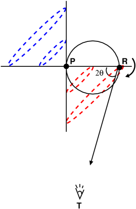
Further, we will assume that the plane of the orbit of Reflector (taken circular) contains the visual to Earth, so that the orbit is seen on edge. These are not necessary conditions, and a computer programme can be written to incorporate more general cases if putative data becomes available. The situation is depicted in figure 1.
The beam cone intersects the orbit of Reflector in at least one point, and its angular position along the orbit will depend on the opening of Pharus’s cone (angular width), controlled by its magnetic anomaly or inclination angle to the rotation axis.
If Reflector happens to be at the orbit-beam cone crossing when Pharus illuminates it, the reflected radiation might reach Earth at an instant when the pulsar is, in theory, still.
In our simple computer simulation, the intensity of the radiation of Pharus for a given X-ray wavelength will be taken as the unity at maximum, with a Gaussian profile (this plays no role as long as it is a simple function). The intensity of the beam diffracted by reflector will naturally be smaller. This will be partly due to absorption in Reflector, but primarily because the illumination of its surface will decrease with the square of the distance to Pharus,
| (1) |
where is the effective emitting radius of Pharus (of order 100 km for a typical neutron-star pulsar of radius 10 km, as estimated from the magnetosphere’s end at the light cylinder (Saito et al., 1997)) and the radius of the orbit of Reflector. A further decrease of the reflected signal is brought about by the fraction of the surface that reflects Pharus’s beam. This, in analogy with the lunar phases, is
and is incorporated in the example below.
To keep the signal of Reflector within one or few percent of the intensity of Pharus, Reflector has to orbit in close range to Pharus. However, to have a clearer line-shape for the signal it is convenient to have the orbital period of Reflector, to be of the same order as, (but larger than) the spinning period of Pharus, , which demands, because of Kepler’s third law, and in terms of the two star’s masses and Cavendish’s constant ,
larger orbital radii. Given the tension between the two requirements, we compromise to an orbit of order 10000 km (or a period of order ), which is certainly small enough for relativistic corrections to the orbit to play a role, but we will ignore these. (Note that the double neutron star binary with the shortest orbital period is, as of 2004, 2.45 hours in J0737–3030 (Lyne et al., 2004), so that this case study is low compared with current observations of binary systems, but not impossible).
To check that relativistic corrections are not a major source of uncertainty, we take the relevant equations of General Relativity (Peters, 1964) to estimate in turn the power radiated by gravitational waves, the rate of decrease of the semi major axis, the rate of decrease of the orbital period, and the total time for collapse of the binary, yielding, for typical values of the star’s mass and the period/orbital radius just quoted,
| (2) | |||
| (3) | |||
| (4) | |||
| (5) |
Thus, relativistic effects may be neglected if the observation time of pulsar profiles is very short compared with the time to collapse just estimated.
The extraction of the reflection angle for a given binary system might employ the variation of Pharus’ velocity along the line of sight in its orbital motion, causing a first–order kinematic Doppler shift, affecting the spectral shape of the main peak. Analyzing the red/blue shift of the peak over several periods one can determine from the data to what angular position along the orbit does a given main peak of Pharus correspond. Then one just needs to note that the position of Reflector a short time later takes a correction
| (6) |
3 Bragg diffraction at Reflector
The principle of Bragg diffraction is illustrated in figure 2.
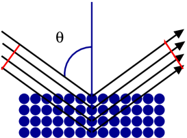
A crystalline material acts as a difraction grating. A beam of a given wavelength is reflected, by constructive interference, only when Bragg’s law is met
| (7) |
with the spacing between crystal planes, the radiation wavelength, the reflection angle taken from the vertical, and an integer number. Because the sine is smaller than one and greater, this condition can only be satisfied for wavelengths smaller than twice the crystal spacing.
It is known that atomic iron crystals present a body-centered cubic structure with spacing called ferrite at temperatures above or below . Austenite, a crystallization in a face-centered cubic lattice is stable between these two temperatures (Kawasaki steel, 1997) . These cubic crystallizations are already quite optimal and therefore we can assume that the outermost layer of a neutron star, if crystalline iron, will employ them depending on the temperature. Therefore, if the spacing is not altered in neutron stars, the characteristic wavelengths that need to be scanned are .
That the lattice spacing remains, at the neutron star’s surface, similar to that under earthly conditions requires closer examination. First, we show from a macroscopic point of view that gravitational forces at the very surface of Reflector only moderately deform the crystal. Indeed, the inwards gravitational acceleration at the surface is of order . This causes a force per unit area to depth inside the crust (the density of iron being ). Given the Young modulus of iron, , the distortion of the lattice expected is , which grows linearly with depth. The penetration depth of X-rays depends on their frequency and is typically in crystalline iron (Randle & Engler, 2000)(this amounts to a number of about planes necessary to totally diffract the beam). remains significantly smaller than 1 for all layers within this penetration depth.
Another argument is to consider that characteristic microscopic atomic forces are of order N and these, based in Coulomb interactions between electrons and iron nuclei, are also much stronger than gravitational forces exerted on the atomic mass, of order N. Thus, for the purposes of X-ray diffraction, crystalline iron at the star’s surface is similar to that on Earth, with somewhat broadened lines. This is in spite of the increasingly large deformation that happens with depth. Deeper in the crust densities are enormous, easily two orders of magnitude larger than in Earth, so that the atomic crystal is deformed and diffraction occurs at lower wavelengths. However such depths are hard to reach for X-rays that diffract near the surface.
However, the radiation wavelength that we observe is red-shifted respect to the radiation reflected at the star’s surface, due to the gravitational potential in General Relativity. This effect brings about a correction necessary when extracting the crystal spacing from Bragg’s law, since the appearing in that formula is taken at the star’s surface. One finds a gravitational red shift
| (8) |
in terms of the star radius and mass. (This correction factor is about 1.3 for a typical neutron star).
Equation (7) would then be corrected due to the gravitational red–shift to
| (9) |
This formula can also be corrected for kinematic Doppler shift due to the orbital motion of Reflector as neeed be, simply substituting the factor .
If a diffraction pattern was suspected, one could conceivably identify the form of crystallization (whether ferrite or austenite) by the lines present. This is possible because the fcc and bcc crystal have different symmetry planes. In terms of the Miller indices , , and the unit-cell size , the spacing between those planes is given by
| (10) |
and combining with Eq.(9)
| (11) |
For a bcc lattice only those combinations where is an even integer occur in the diffraction pattern. An fcc lattice diffracts instead for all odd or all even.
| P | P | ||||
| 111 | 1.73 | 8 | 011 | 1.41 | 12 |
| 002 | 2 | 6 | 002 | 2 | 6 |
| 112 | 2.45 | 24 | |||
| 022 | 2.83 | 12 | 022 | 2.83 | 12 |
| 113 | 3.32 | 24 | 013 | 3.16 | 24 |
| 222 | 3.46 | 8 | 222 | 3.46 | 8 |
| 123 | 3.74 | 48 | |||
| 004 | 4 | 6 | 004 | 4 | 6 |
| 331 | 4.36 | 24 | 411 | 4.24 | 24 |
| 024 | 4.47 | 24 | 024 | 4.47 | 24 |
| 233 | 4.69 | 24 | |||
| 224 | 4.9 | 24 | 224 | 4.9 | 24 |
| 333 | 5.2 | 32 | 105 | 5.1 | 72 |
| 511 | 314 | ||||
| 215 | 5.48 | 48 | |||
| 044 | 5.66 | 12 | 044 | 5.66 | 12 |
| 135 | 5.92 | 48 | |||
| 035 | 5.83 | 48 | |||
| 334 | |||||
| 424 | 6 | 30 | 424 | 6 | 30 |
| 006 | 006 |
Table 1 shows the first few diffraction lines expected. Given are the Miller indices, the distance between diffracting planes with given Miller indices in lattice units, and the multiplicity of planes yielding the same distance (and thus diffracting at the same wavelength), the intensity of the diffracted beam being proportional to this multiplicity. Additional factors influencing the intensity of a given line are the Lorentz-polarization factor and the atomic scattering factor for Fe, given in (Cullity & Stock, 2001).
4 Line shape of the pulsar
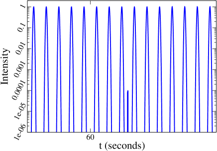
An example of an observable line-shape for the binary X-ray pulsar is plotted in figure 3.
One sees that, in addition to the pulse of Pharus, a smaller signal due to Reflector appears. The intensity of this pulse depends on the distance between Pharus and Reflector, but Kepler’s third law links this to the orbital period, and thus the relative intensity of the secondary pulse is not independent of its repetition rate.
This periodic reapparition of Reflector every depends on the orbital coincidence that it crosses the cone subtended by Pharus’s beam when it is irradiated. This happens when, for two integers and ,
| (12) |
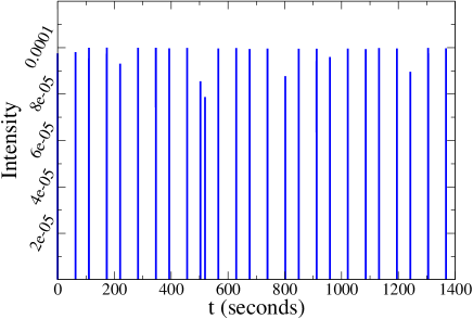
This rational number relation does not need to be exact, in view of the time-width of Pharus’s beam. We take some ad–hoc values for illustrational purposes that are and . The resulting line shape, where the secondary is clearly observed, is represented in figure 3. Note the secondary misses several periodic apparitions since the spin and orbital period are not perfectly matched (which we expect to be borne in reality). In figure 4 we represent the same data for shorter periods so one can discernt the Gaussian shape of the main pulse.
What distinguishes Bragg diffraction from other astrophysical phenomena that produce complicated secondaries (indeed pulsars have rather varying line-shapes (Graham-Smith, 2003) is that the peak appears at very specific wavelengths. Since in eq. (7) is an integer, the secondary appears at the wavelength sequence
and at other specific frequencies as dictated by the various planes in table 1.
In addition, for the degenerate case (orbit seen edge-on) that we have chosen, there is one additional crossing of Pharus’s beam cone with Reflector’s orbit. The reflection angles appearing in Bragg’s law for these crossings satisfy, given that the binary system subtends a negligible angle as seen from Earth, . Then one can easily see that a second series of wavelengths
with will also show a secondary peak (same for other sequences caused by additional reflecting planes).
Another very interesting degenerate case occurs when the magnetic axis of Pharus is perpendicular to its precession axis: then the X-ray beam swipes the entire orbit of Reflector, and yields the possibility of detecting, at short X-ray wavelengths, several diffraction maxima.
5 Prospects for detection
Detection of such binary system in our galactic neighboorhood would be a not too-difficult task. For example, consider the well-studied Crab pulsar at a distance of some . A couple of days ( seconds) of data taken in 2001 (Tennant, 2001) yield 0.19 counts per second, mostly in the region, corresponding to a fraction of a nanometer and ideally suited for diffraction off iron.
Should the Crab pulsar have had a close-orbiting companion when these data were taken (we obviously do not believe this to be the case for many other reasons, among them that the violent merger would have occurred in the intervening decade), it could probably have been detected with the existing satellite missions Chandra and XMM-Newton. To see it, just notice that between the maximum sensitivity at the peak of the spectrum (Tennant, 2001) and the high energy tail where one runs out of counts, there are three orders of magnitude. This means that the instrument should have been able to find an intensity ratio of Reflector to Pharus of . With a two to three week observation time, the requisite sensitivity would have been reached by the increased statistics.
The same sensitivity can be found in other published work, for example (Weisskopf et al , 2004). Observations of the Crab, Vela, Geminga and other pulsars concur in yielding three decades of sensitivity in spectral structure between maximum and minimum sensitivity.
However the likelihood that a merger happens within the galaxy is relatively small during a human lifetime. The rate of coalescence of two-neutron star binary systems has been estimated in several works (Kim , 2003; Regimbau , 2005), given its interest for the gravitational wave detection programme at LIGO and VIRGO, as well as possible upgrades of these machines.
Estimates for double neutron star mergers inside our galaxy are (in order of magnitude) . To obtain a good rate that allows a potential detection in, for example, a decade of operation, one needs to be able to detect the X-ray source to a distance of up to 30-40 (more than a hundred times the galactic size) to include many other star formations of the local group. This is the goal for the gravitational wave detectors.
The detection of X-ray diffraction in a binary system would point out to the tightness of the orbit and the temporal approaching of its final collision. Therefore it would be interesting to explore, in future work, the possibility of employing X-ray diffraction as an early-warning system for those detectors.
6 Conclusions and outlook
In conclusion, we have attempted to develop an astronomical observable able to test the hypothesis of a crystalline iron crust in cold neutron stars. The search we suggest is for a secondary pulse in an X-ray pulsar indicating a binary system. The tell-tale of crystalline structure is the appearance of this secondary for a specific sequence of wavelengths Several such frequency sequences may appear due to the various crystal planes and to the possibility of observing Reflector at more than one angle along the orbit.
The phenomenon is quite the opposite of an eclipsing binary. Instead, here the companion star is dark most of the time and only brightens when Bragg’s diffraction condition is satisfied.
To extract the crystal spacing from data one could follow the (simplified) steps
-
•
Detect a potential binary system with the proposed pattern. Since the absolute calibration of the energy is not known a priori due to various red shifts, one way to proceed would be to study the intensity cross correlations as a function of energy.
-
•
Measure the period of Pharus’s main pulse, .
-
•
Perform a simple rational number analysis to obtain an approximate for Reflector.
-
•
Obtain the angle by a Doppler measurement or possibly a direct orbital reconstruction.
-
•
Given , the largest wavelength where Reflector is seen, after any corrections needed, use Bragg’s law to obtain .
X-ray diffraction might also occur at the surface of a cold white-dwarf acting as Reflector. A difference between such stars and neutron stars is that nuclear fusion chains are generally thought not to be complete in the progenitor star, one does not expect to find iron but a mixture of lighter elements such as oxygen, neon, silicon, etc. It would surely be interesting and complicated to examine any data that may become available. Immediately one notices that the observation of the iron crust on a cold neutron star is an additional test of the efficiency of fusion in its very massive progenitor (believed to be completely efficient).
Finally, as with many other theoretical proposals in high-energy as well as astrophysics, discovery with present instrumentation will involve a good amount of serendipity, although “accidental” discoveries occur, while serious exclusion bounds that would put in question the existence of a crystalline crust are much more difficult and should await a future generation X-ray satellite.
References
- Bombaci (2007) I. Bombaci, Eur. Phys. J. A 31 (2007) 810.
- Borkowski et al. (2007) K. J. Borkowski, S. P. Hendrick and S. P. Reynolds, arXiv:0711.3140 [astro-ph].
- Kunzl (2001) Thomas Kunzl, “Coherent and incoherent radiation processes in pulsars”, dissertation presented to the University of Munich, 2001, available at doc.ub.uni-muenchen.de/338/.
- Campana et al. (2009) R. Campana, E. Massaro, T. Mineo and G. Cusumano, arXiv:0903.3655 [astro-ph.HE].
- Chamel & Haensel (2008) N. Chamel and P. Haensel, Living Rev. Rel. 11, 10 (2008) [arXiv:0812.3955 [astro-ph]].
- Cottam et al. (2002) J. Cottam, F. Paerels and M. Mendez, Nature 420 (2002) 51-54.
- Cullity & Stock (2001) B.D. Cullity and S.R. Stock, “Elements of X-Ray Diffraction”, Prentice Hall, Upper Saddle River, NJ (2001).
- de Young (1991) D. S. de Young, Science 19 252 (1991) 389-396.
- Graham-Smith (2003) F. Graham-Smith, 2003. Rep. Prog. Phys. 66 (2003) 173-238.
- Haensel et al. (2006) P. Haensel, A. Y. Potekhin and D. G. Yakovlev, Neutron stars 1: equation of state and structure, Springer-Verlag, New York-Heidelberg-Berlin (2006).
- Huber et al. (1994) H. Huber, F. Weber and M. K. Weigel, Phys. Rev. C 50 (1994) R1287.
- Kapoor & Shukre (1998) R. C. Kapoor and C. S. Shukre, ApJ 501 (1998) 228-241, doi: 10.1086/305804.
- Kawasaki steel (1997) Kawasaki Steel 21st Century Foundation, “An Introduction to Iron and Steel Processing” (1997) (unpublished).
- Klahn (2006) T. Klahn et al., Phys. Rev. C 74 (2006) 035802 [arXiv:nucl-th/0602038].
- Yakovlev & Pethick (2004) D. G. Yakovlev and C. J. Pethick, Ann. Rev. Astron. Astrophys. 42 (2004), 169-210 (see section 5.7).
- Imshennik et al. (2002) V. S. Imshennik, K. V. Manukovskii, D. K. Nadyozhin and M. S. Popov, Astron. Lett. 28 (2002) 821 [arXiv:astro-ph/0402153].
- Lewin et al. (1997) Walter H. G. Lewin, Jan van Paradijs, Edward P. J. van den Heuvel (Eds.), “X-ray binaries”, Cambridge Univ. Press (1997).
- Lyne et al. (2004) Andrew Lyne et al., Science 303 (2004) 1153.
- Saito et al. (1997) Y. Saito et al. Astrophys. J. 477:L37-L40 (1997).
- Peters (1964) Philip C. Peters, Physical Review 136 (1964) B1224-B1232.
- Randle & Engler (2000) V. Randle and O. Engler, “Texture Analysis”, table 4.2, CRC Press Boca Raton, FL (2000).
- Shternin et al. (2007) P. S. Shternin et al., Mon. Not. R. Astron. Soc., 382, L43–L47 (2007).
- Suleimanov et al. (2009) V. F. Suleimanov, A. Y. Potekhin and K. Werner, arXiv:0905.3276 [astro-ph.SR].
- Thorsett & Chakrabarty (1999) S. E. Thorsett and D. Chakrabarty, Astrophys. J. 512 (1999) 288 [arXiv:astro-ph/9803260].
- Tennant (2001) A. F. Tennant et al. Astrophys. J. 559 (2001) L173-L176.
- Weisskopf et al (2004) M. C. Weisskopf et al. Astrophys. J. 601 (2004) 1050-1057.
- Kim (2003) C. , Kim V. Kalogera and D. R. Lorimer, Astrophys. J. 584 (2003) 985.
- Regimbau (2005) T. Regimbau et al. Class. Quantum Grav. 22 (2005) S935.