e-mail shima@eng.hokudai.ac.jp, Phone +81-11-706-6624, Fax +81-11-706-6859
2 Department of Socio-Environmental Engineering, Graduate School of Engineering, Hokkaido University, Sapporo 060-8628, Japan
XXXX
Pressure-induced structural transitions in multi-walled carbon nanotubes
Abstract
\abstcolWe demonstrate a novel cross-sectional deformation, called the radial corrugation, of multi-walled carbon nanotubes (MWNTs) under hydrostatic pressure. Theoretical analyses based on the continuum elastic approximation have revealed that MWNTs consisting of more than ten concentric walls undergo elastic deformations at critical pressure GPa, above which the circular shape of the cross section becomes radially corrugated. Various corrugation modes have been observed by tuning the innermost tube diameter and the number of constituent walls, which is a direct consequence of the core-shell structure of MWNTs.
pacs:
61.46.Fg, 62.50.-p, 64.70.Nd, 81.05.Tp[width=0.46]fig_00 \titlefigurecaptionCross-sectional views of multi-walled carbon nanotube under high hydrostatic pressure: elliptic deformation with the mode index (left), and radial corrugations with (center) and (right). The index indicates the circumferential wave number of the deformed cross section.
1 Introduction
An important mechanical feature of carbon nanotubes is their high flexibility in the radial direction. Radial stiffness of an isolated carbon nanotube is much less than axial stiffness [1], which result in an elastic deformation of the cross section on applying a hydrostatic pressure. Such a pressure-induced radial deformation yields significant changes in electronic [2, 3, 4, 5, 6, 7, 8, 9] and optical [10, 11, 12, 13] properties, indicating the relevance of the deformation in carbon nanotube applications. Thus far, many experimental and theoretical studies have been carried out on this issue [14, 15, 16, 17, 18, 19, 20, 21, 22, 23, 24, 25, 26, 27, 28, 29, 30, 31, 32, 33, 34]. Most of them focused on single-walled nanotubes (SWNTs) and their bundles, and revealed flattening and polygonalization in the cross section of SWNTs under pressures of the order a few GPa [10, 16]. Contrary to the intensive studies on SWNTs, radial deformation of multiwalled nanotubes (MWNTs) still remains to be explored. Intuitively, the multiple-shell structure of MWNTs is thought to enhance the radial stiffness of MWNTs. However, when the number of concentric walls is much greater than unity, outside walls have large diameters so that external pressure may lead to a mechanical instability in the outer walls. This local instability implies a novel cross-sectional shape transition of MWNTs different from the cases of SWNTs.
This paper shows a new class of radial deformation, called radial corrugation, of MWNTs consisting of more than ten concentric walls. In a corrugation mode, outside walls exhibit wavy structures along the circumference as depicted in Titlefigure. We demonstrate that various corrugation modes can take place above critical hydrostatic pressure , in which depends on the innermost tube diameter and the number of constituent walls . It should be emphasized that radial corrugation we have found is a direct consequence of the core-shell structure of MWNTs, and thus is differernt inherently from simple radial collapse observed in SWNTs.
2 Continuum elastic-shell theory
2.1 Outline
The stable cross-sectional shape of a MWNT under a hydrostatic pressure is evaluated by using the continuum elastic theory for cylindrical shells [35, 36, 37, 38]. The mechanical energy of a MWNT per unit axial length is written as
| (1) |
where is the deformation energy of all concentric walls, is the interaction energy of all adjacent pairs of walls, and is the potential energy of the applied pressure. All the three energy terms are functions of and the deformation amplitudes and that describe the radial and circumferential displacements, respectively, of the th wall. See Eq. (8) below for the precise definitions of and .
Our objective is the optimal displacements and that minimize the total energy under a given pressure . To this aim, we apply the variation method to with respect to and , and then obtain the stable cross-sectional shape of a MWNT under [39]. This strategy requires to derive explicit forms of , and as functions of , and , which we shall resolve in the subsequent discussions.
2.2 Strain-displacement relation
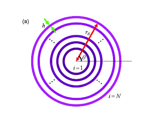
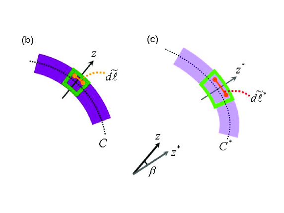
We first consider the circumferential strain of a hollow cylindrical shell due to cross-sectional deformation. Suppose a circumferential line element of length lying within the cross section of the shell with thickness (See Fig. 1). The tilde attached to means that we consider the quantity at arbitrary point within the cross section. We shall see later (i.e., in Eq. (8) ) that the strain at arbitrary point is determined approximately by the strain just on the controidal circle denoted by in Fig. 1. This fact allows us to yield a simplified relation between the strain and displacements of the shell as given in Eqs. (9) and (10).
The extentional strain of the circumferential line element is defined by
| (2) |
Here , and is the length of the line element after deformation (The asterisk symbolizes the quantity after deformation). The coordinates , of the element after deformation is given by
| (3) |
where and are components of the displacement vector in the radial and circumferential directions, respectively. It thus follows that
| (4) | |||||
From Eq. (2), we have . Hence, squaring the both sides and then rearranging the result give
| (5) |
For , the term can be omitted. Hence, we have from Eqs. (4) and (5) that
| (6) |
where , etc. The last term in Eq. (6) is associated with the rotation of the line element due to deformation. The rotation angle consists of two parts: i) a clockwise component due to the spatial variation of in the circumferential direction, and ii) a counterclockwise one due to the circumferential displacement of the element. Combination of the two parts gives
| (7) |
which has a positive value in the counterclockwise sense.
The formula (6) is valid for arbitrary large rotation . Particularly when and are both sufficiently small (but finite), we may neglect the second term in the right side in Eq. (6). (Here we exclude the possibility that or is of the order of or larger.) We further assume that normals to the undeformed centroidal circle remain straight, normal, and inextensional during the deformation (See Fig. 1). As a result, and are expressed by
| (8) |
where and denote the displacements of a point just on , and is a radial coordinate measured from . By substituting (8) into (6), we attain the strain-displacement relation such as [40]
| (9) |
with the definitions:
| (10) |
Here is the radius of the undeformed circle . The results (9) and (10) state that the circumferential strain at arbitrary point in the cross section is determined by the displacements and of a point just on the undeformed controidal circle .
2.3 Deformation energy
We are ready to derive the explicit form of the deformation energy . Suppose the th cylindrical wall of a long and thin circular tube with thickness . A surface element of the cross-sectional area of the wall is expressed by . The stiffness of the surface element for stretching along the circumferential direction is given by
| (11) |
where and are Young’s modulus and Poisson’s ratio, respectively, of the wall. Thus, the deformation energy of the th wall per unit axial length is written as
| (12) |
| (13) |
which tells us the dependence of on and .
| Young’s modulus | Poisson’s ratio | Wall thickness |
|---|---|---|
| [TPa] | [nm] |
2.4 Inter-wall coupling energy
Secondly, the explicit form of is described by
| (14) | |||||
The vdW interaction coefficients are functions of and and defined by [38]
| (15) |
where denotes the chemical bond length between neignbouring carbon atoms within a layer ( nm), and and are the parameters that determine the vdW interaction between two layers ( meV and nm) [41]. In Eq. (15), we have set
| (16) |
with , and the wall spacing nm according to Ref. [42].
2.5 Pressure-induced energy
We finally derive an explicit form of . Since is the negative of the work done by the external pressure during cross-sectional deformation, it is expressed as
| (17) |
Here, is the area surrounded by the th wall after deformation (the sign of is assumed to be positive inward). It is obtained by the line integral , or equivalently
| (18) |
From Eqs. (18) and (3) as well as the periodicity relation , we obtain
3 Critical pressure curve
3.1 Evaluating critical pressure
Our aim is to evaluate the critical pressure above which the circular cross section of a MWNT is elastically deformed into non-circular one. This is achieved by the following procedure [39]. First, we decompose the radial displacement terms as , where indicates a uniform radial contraction at and describes a deformed, non-circular cross section observed just above . Similarly, we can write , since at . Next, we apply the variation method to with respect to and , which results in a system of linear differential equations with respect to and . Then, substituting Fourier series expansions of and into the differential equations, we obtain the matrix equation . Here, the vector consists of the Fourier components of and with all possible and all Fourier components labeled by , and the matrix involves one variable as well as elasticity parameters. Finally, solving the secular equation with respect to , we obtain a sequence of discrete values of ; among these s, the minimum one serves as the critical pressure immediately above which the circular cross section of MWNTs becomes radially deformed.
3.2 Wall-number dependence
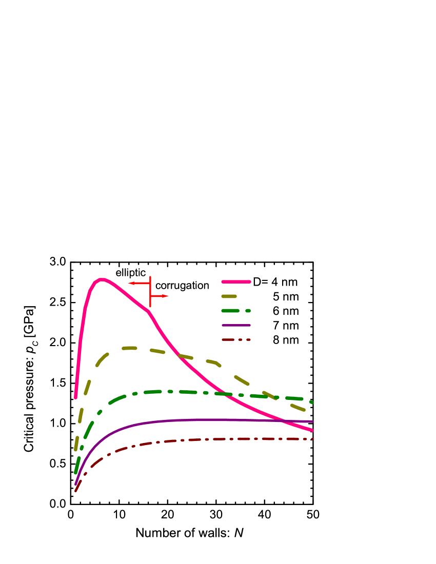
Figure 2 shows numerical results of critical pressures . In the left-side figure, is plotted as a function of the number of concentric walls with the innermost tube diameter being fixed. For all , increase with followed by a slow decay or saturating constant value. The increase in in the region of small is attributed to the enhancement of radial stiffness of the entire MWNT by encapsulation. In contrast, the decay in indicates local instability in outside walls that causes radial corrugation of MWNTs with .
To be noteworthy is the occurrence of a kink in for small . In the curve of for nm, for instance, a kink appears at to the right of which the value of decay monotonically. The most striking is the fact that this kink determines the phase boundary between the elliptic deformation phase and the radial corrugation phases (as indicated by red arrows in the left-sided figure of Fig. 2). We have found that -walled nanotubes with exhibit some radial corrugation just above , while those with show only the elliptic deformation. This senario also holds for the case of nm, where the phase boundary kink occurs at . Which kind of corrugation mode (i.e., what number of the mode index ) takes place is dependent on the values of and , as clarified later in Fig. 3.
3.3 Innermost-tube-diameter dependence
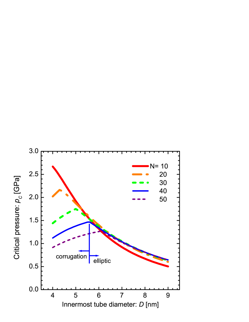
The right-side figure in Fig. 2 illustrates the -dependence of for various . Similarly to the left-side figure, a kink appears for each curve except for . This kink again serves as the phase boundary between the elliptic and corrugation phases; if a kink occurs at , then it separates radial corrugation phases from the elliptic deformation phase .
It is interesting that in the elliptic phase, all the results (except for ) collapse onto a single curve. This means that the number of walls is irrelevant in determining for MWNTs with large . In other words, encapsulation by increasing gives no contribution to the radial stiffness of those MWNTs with large . This fact implies the availiability of simplified equations for estimating of MWNTs with large ; establishing such simplified equations is currently in progress.
4 Radial corrugation of MWNTs
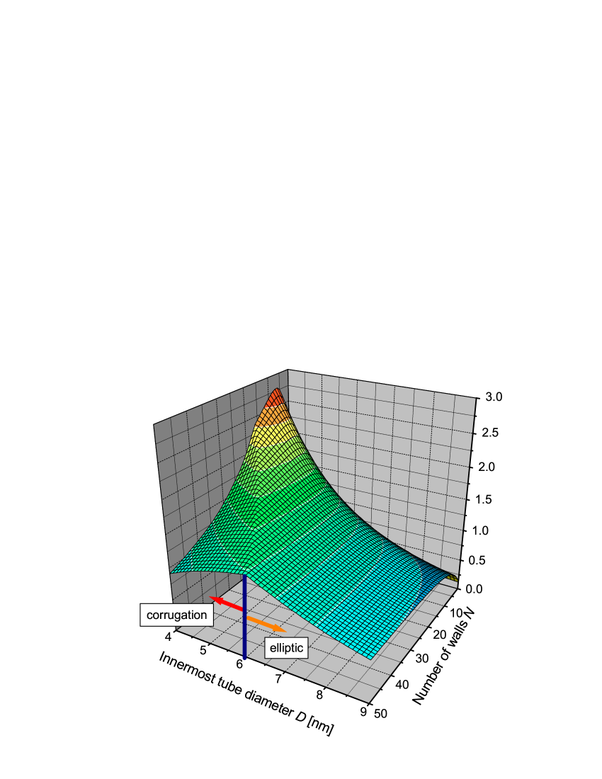
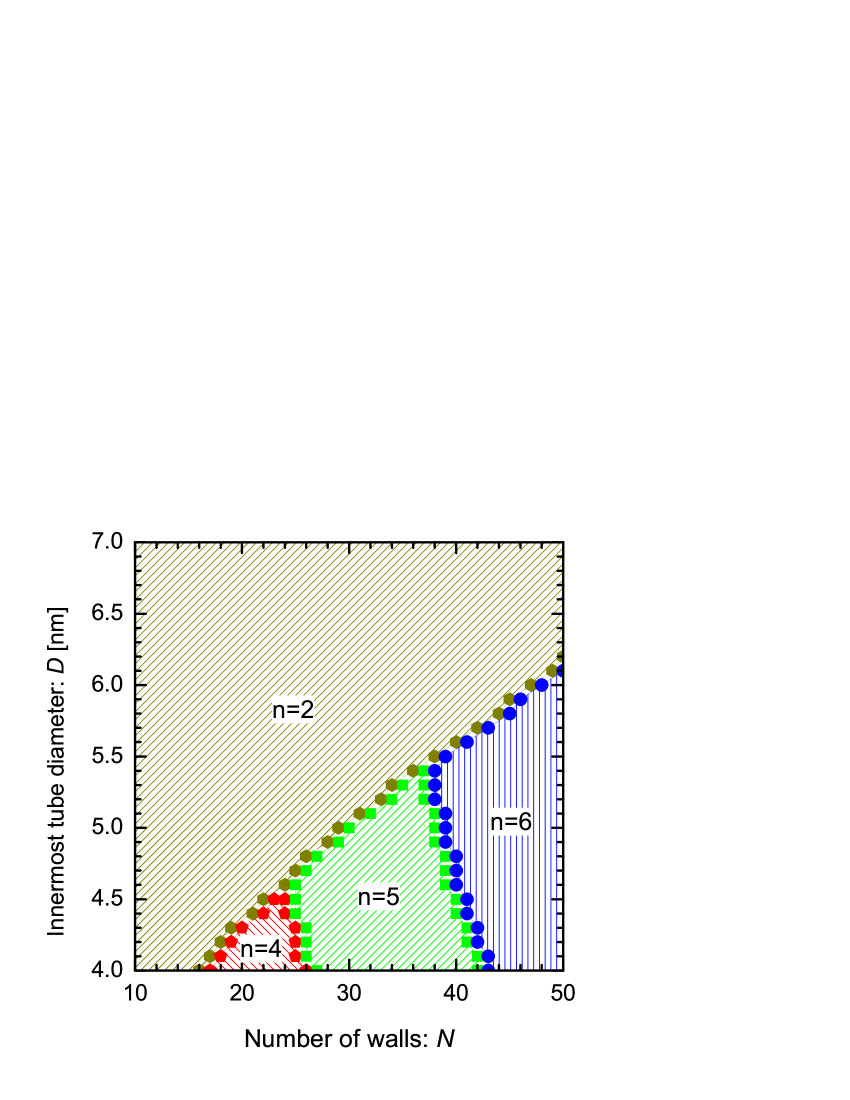
All the numerical results of are summarized into the three-dimensional plot ; see the left-side in Fig. 3. This plot makes clear the optimal values of and that maximize (or minimize) the radial stiffness of MWNTs. We also obverve a ridge line extending from the top to the bottom of the surface. The ridge line corresponds to the phase-boundary kinks discussed in the previous section. In fact, multiple corrugation modes take place in the region to the left of the ridge line, as demonstrated in the phase diagram; see the right-side of Fig. 3. Interestingly, multiple corrugation modes are formed depending on the values of and . We see that smaller and larger favor corrugation modes, in which larger yield higher corrugation modes with larger .
5 Concluding remarks
We have demonstrated the presence of multiple radial corrugations peculiar to MWNTs under hydrostatic pressures. Theoretical investigations based on the continuum elastic theory have revealed that MWNTs consisting of a large number of concentric walls undergo elastic deformations at critical pressure 1 GPa, above which the cross-sectional circular shape becomes radially corrugated. A phase diagram has been established to obtain the requisite values of and for observing a desired corrugation mode. It is hoped that our results should be verified by high-pressure experiments on MWNTs as well as atomic-scale large-scale simulations [43, 44, 45].
Another interesting subject is to explore the structural deformation effect on the quantum-mechanical properties of electrons moving in the corrugated carbon walls. It has been known [46, 47, 48] that mobile electrons whose motion is confined to a two-dimensional curved thin layer behave differently from those on a conventional flat plane; this results from the occurrence of effective scalar- [49, 50] and vector- [51] potential energies induced by geometric curvature of the underlying layer. Hence, quantum nature of electrons moving in the corrugated nanotube will be strongly affected by geometric curvature of the walls, which remains thus far unsettled. Intensive studies on the issues mentioned above will shed light on novel MWNT applications based on cross-sectional deformation.
We acnowledge M. Arroyo and R. Dandoloff for stimulating discussions. This study was supported by a Grant-in-Aid for Scientific Research from the MEXT, Japan. One of the authors (H.S) is thankful for the financial support from Executive Office of Research Strategy in Hokkaido University. A part of the numerical simulations were carried using the facilities of the Supercomputer Center, ISSP, University of Tokyo.
References
- [1] I. Palaci, S. Fedrigo, H. Brune, C. Klinke, M. Chen, and E. Riedo E, Phys. Rev. Lett. 94 (2005) 175502.
- [2] C. J. Park, Y. H. Kim, and K. J. Chang, Phys. Rev. B 60 (1999) 10656.
- [3] M. S. C. Mazzoni and H. Chacham, Appl. Phys. Lett. 76 (2000) 1561.
- [4] D. S. Tang, Z. X. Bao, L. J. Wang, L. C. Chen, L. F. Sun, Z. Q. Liu, W. Y. Zhou, and S. S. Xie, J. Phys. Chem. Solids 61 (2000) 1175.
- [5] C. Gómez-Navarro, J. J. Sáenz, and J. Gómez-Herrero, Phys. Rev. Lett. 96 (2006) 076803.
- [6] J. Z. Cai, L. Lu, W. J. Kong, H. W. Zhu, C. Zhang, B. Q. Wei, D. H. Wu, and F. Liu, Phys. Rev. Lett. 97 (2006) 026402.
- [7] M. Monteverde, G. Garbarino, M. Núñez-Regueiro, J. Souletie, C. Acha, X. Jing, L. Lu, Z. W. Pan, S. S. Xie, and R. Egger, Phys. Rev. Lett. 97 (2006) 176401.
- [8] H. Taira and H. Shima, Surf. Sci. 601 (2007) 5270.
- [9] T. Nishio, Y. Miyato, K. Kobayashi, K. Matsushige, and H. Yamada, Appl. Phys. Lett. 92 (2008) 063117.
- [10] U. D. Venkateswaran, A. M. Rao, E. Richter, M. Menon, A. Rinzler, R. E. Smalley, and P. C. Eklund, Phys. Rev. B 59 (1999) 10928.
- [11] R. S. Deacon, K. C. Chuang, J. Doig, I. B. Mortimer, and R. J. Nicholas, Phys. Rev. B 74 (2006) 201402(R).
- [12] S. Lebedkin, K. Arnold, O. Kiowski, F. Hennrich, and M. M. Kappes, Phys. Rev. B 73 (2006) 094109.
- [13] M. J. Longhurst and N. Quirke, Phys. Rev. Lett. 98 (2007) 145503.
- [14] J. Tang, J. C. Qin, T. Sasaki, M. Yudasaka, A. Matsushita, and S. Iijima, Phys. Rev. Lett. 85 (2000) 1887; J. Phys. Condens. Matt. 14 (2002) 10575.
- [15] M. J. Peters, L. E. McNeil, J. P. Lu, and D. Kahn, Phys. Rev. B 61 (2000) 5939.
- [16] S. M. Sharma, S. Karmakar, S. K. Sikka, P. V. Teredesai, A. K. Sood, A. Govindaraj, and C. N. R. Rao, Phys. Rev. B 63 (2001) 205417.
- [17] S. Rols, I. N. Gontcharenko, R. Almairac, J. L. Sauvajol, and I. Mirebeau, Phys. Rev. B 64 (2001) 153401.
- [18] S. Reich, C. Thomsen, and P. Ordejon, Phys. Rev. B 65 (2003) 153407; Phys. Stat. Sol. B 235 (2003) 354.
- [19] A. Pantano, D. M. Parks, and M. C. Boyce, J. Mech. Phys. Solid. 52 (2004) 789.
- [20] J. A. Elliott, L. K. W. Sandler, A. H. Windle, R. J. Young, and M. S. P. Shaffer, Phys. Rev. Lett. 92 (2004) 095501.
- [21] P. Tangney, R. B. Capaz, C. D. Spataru, M. L. Cohen, and S. G. Louie, Nano Lett. 5 (2005) 2268.
- [22] V. Gadagkar, P. K. Maiti, Y. Lansac, A. Jagota, and A. K. Sood, Phys. Rev. B 73, (2006) 085402.
- [23] X. Wang and H. K. Yang, Phys. Rev. B 73, (2006) 085409.
- [24] S. Zhang, R. Khare, T. Belytschko, K. J. Hsia, S. L. Mielke, and G. C. Schatz, Phys. Rev. B 73 (2006) 075423.
- [25] M. Hasegawa and K. Nishidate, Phys. Rev. B 74 (2006) 115401.
- [26] Y. Huang, J. Wu, and K. C. Hwang, Phys. Rev. B 74 (2006) 245413.
- [27] X. Yang, G. Wu, and J. Dong, Appl. Phys. Lett. 89 (2006) 113101.
- [28] D. Christofilos, J. Arvanitidis, G. A. Kourouklis, S. Ves, T. Takenobu, Y. Iwasa, and H. Kataura, Phys. Rev. B 76 (2007) 113402.
- [29] J. Peng, J. Wu, K. C. Hwang, J. Song, and Y. Huang, J. Mech. Phys. Solid. 56 (2008) 2213.
- [30] C. E. Giusca, Y. Tison, and S. R, P. Silva. Nano Lett. 8 (2008) 3350.
- [31] Y. Wu, M. Huang, F. Wang, X. M. Henry Huang, S. Rosenblatt, L. Huang, H. Yan, S. P. O’Brien, J. Hone, and T. F. Heinz, Nano Lett. 8 (2008) 4158.
- [32] B. W. Jeong, J. K. Lim, and S. B. Sinnott, Appl. Phys. Lett. 92 (2008) 253114.
- [33] Y. D. Kuang, X. Q. He, C. Y. Chen, and G. Q. Li, Carbon 47 (2009) 279.
- [34] W. B. Lu, B. Liu, J. Wu, J. Xiao, K. C. Hwang, S. Y. Fu, and Y. Huang, Appl. Phys. Lett. 94 (2009) 101917.
- [35] C. Q. Ru, Phys. Rev. B 62 (2000) 16962.
- [36] C. Y. Wang, C. Q. Ru, and A. Mioduchowski, Int. J. Solids. Struct. 40 (2003) 3893.
- [37] H. S. Shen, Int. J. Solids. Struct. 41 (2004) 2643.
- [38] X. Q. He, S. Kitipornchai, and K. M. Liew, J. Mech. Phys. Solids 53 (2005) 303.
- [39] H. Shima and M. Sato, Nanotechnology 19 (2008) 495705.
- [40] J. L. Sanders Jr., Quart. Appl. Math. 21 (1963) 21.
- [41] R. Saito, R. Matsuo, T. Kimura, G. Dresselhasu, and M. S. Dresselhaus, Chem. Phys. Lett. 348 (2001) 187.
- [42] C. H. Kiang, M. Endo, P. M. Ajayan, G. Dresselhaus, and M. S. Dresselhaus, Phys. Rev. Lett. 81 (1998) 1869.
- [43] I. Arias and M. Arroyo, Phys. Rev. Lett. 100 (2008) 085503.
- [44] M. Arroyo and I. Arias, J. Mech. Phys. Solids 56 (2008) 1224.
- [45] J. Zou, X. Huang, M. Arroyo, and S. L. Zhang, J. Appl. Phys. 105 (2009) 033516.
- [46] H. Jensen and H. Koppe, Ann. of Phys. 63 (1971) 586.
- [47] R. C. T. da Costa, Phys. Rev. A 23 (1981) 1982.
- [48] P. C. Schuster and R. L. Jaffe, Ann. Phys. 307 (2003) 132.
- [49] H. Shima, H. Yoshioka and J. Onoe, Phys. Rev. B 79 (2009) 201401. [arXiv:0903.0798]
- [50] S. Ono and H. Shima, Phys. Rev. B 79 (2009) in press. [arXiv:0903.4271]
- [51] H. Taira and H. Shima, arXiv:0904.3149.