Abstract
Laser beams can be made to form bright and dark intensity helices of light. Such helices have a pitch length on the order of a wavelength and may have applications in lithography and the manipulation of particles through optical forces. The formation of bright helices is more strongly constrained by optical resolution limits than that of dark helices, corresponding scaling laws are derived and their relevance for photo-lithography pointed out. It is shown how to arrange dark helices on a grid in massively parallel fashion in order to create handed materials using photo-lithographic techniques.
Bright and dark helices of light
Ole Steuernagel
School of Physics, Astronomy and Mathematics, University of Hertfordshire, Hatfield, AL10 9AB, UK
O.Steuernagel@herts.ac.uk
OCIS codes: (260.3160) Interference; (220.3740) Lithography; (220.4000) Microstructure fabrication; (110.4235) Nanolithography; (160.1585) Chiral media.
References and links
- 1. L. Allen, M. W. Beijersbergen, R. J. C. Spreeuw, and J. P. Woerdman, “Orbital angular momentum of light and the transformation of Laguerre-Gaussian laser modes,” Phys. Rev. A 45, 8185–8189 (1992).
- 2. M. Padgett and L. Allen, “Light with a twist in its tail,” Cont. Phys. 41, 275–285 (2000).
- 3. M. Padgett, J. Courtial, and L. Allen, “Light’s Orbital Angular Momentum,” Physics Today 57, 35–40 (2004).
- 4. M. Harris, C. A. Hill, and J. M. Vaughan, “Optical helices and spiral interference fringes,” Opt. Commun. 106, 161–166 (1994).
- 5. J. M. Vaughan, “Interferometry, atoms and light scattering: one hundred years of optics,” J. Opt. A: Pure Appl. Opt. 1, 750–768 (1999).
- 6. J. Leach, S. Keen, M. J. Padgett, C. Saunter, and G. D. Love, “Direct measurement of the skew angle of the Poynting vector in a helically phased beam,” Optics Express 14, 11919–11924 (2006).
- 7. O. Steuernagel, “Equivalence between focused paraxial beams and the quantum harmonic oscillator,” Am. J. Phys. 73, 625–629 (2005).
- 8. J. Lekner, “LETTER TO THE EDITOR: Helical light pulses,” J. Opt. A: Pure Appl. Opt. 6, L29–L32 (2004).
- 9. J. Hamazaki, Y. Mineta, K. Oka, and R. Morita, “Direct observation of Gouy phase shift in a propagating optical vortex,” Opt. Express 14, 8382–8392 (2006).
- 10. S. M. Baumann, D. M. Kalb, L. H. MacMillan, and E. J. Galvez, “Propagation dynamics of optical vortices due to Gouy phase,” Opt. Express 17, 9818–9827 (2009).
- 11. J. Becker, P. Rose, M. Boguslawski, and C. Denz, “Systematic approach to complex periodic vortex and helix lattices,” Opt. Express 19, 9848–9862 (2011).
- 12. K. Volke-Sepúlveda and R. Jáuregui, “All-optical 3D atomic loops generated with Bessel light fields,” J. Phys. B: At. Mol. Phys. 42, 085303 (2009).
- 13. K. Staliunas, “Vortex Creation in Bose-Einstein Condensates by Diffraction on a Helical Light Grating,” http://www.arxiv.org/abs/cond-mat/9912268 (1999).
- 14. M. Bhattacharya, “Lattice with a twist: Helical waveguides for ultracold matter,” Opt. Commun. 279, 219–222 (2007).
- 15. J. F. Nye and M. V. Berry, “Dislocations in Wave Trains,” Royal Society of London Proceedings Series A 336, 165–190 (1974).
- 16. S. Kuhr, W. Alt, D. Schrader, M. Müller, V. Gomer, and D. Meschede, “Deterministic Delivery of a Single Atom,” Science 293, 278–281 (2001).
- 17. D. Meschede and H. Metcalf, “Atomic nanofabrication: atomic deposition and lithography by laser and magnetic forces,” J. Phys. D: Appl. Phys. 36, R17–R38 (2003).
- 18. L. Marrucci, C. Manzo, and D. Paparo, “Optical spin-to-orbital angular momentum conversion in inhomogeneous anisotropic media,” Phys. Rev. Lett. 96, 163905 (2006).
- 19. J. Leach, M. R. Dennis, J. Courtial, and M. J. Padgett, “Laser beams: Knotted threads of darkness,” Nature 432, 165–165 (2004).
- 20. M. P. MacDonald, L. Paterson, K. Volke-Sepulveda, J. Arlt, W. Sibbett, and K. Dholakia, “Creation and Manipulation of Three-Dimensional Optically Trapped Structures,” Science 296, 1101–1103 (2002).
- 21. F. Pampaloni and J. Enderlein, “Gaussian, Hermite-Gaussian, and Laguerre-Gaussian beams: A primer ,” http://www.arxiv.org/abs/physics/0410021 (2004).
- 22. H. A. Haus, Electromagnetic Noise and Quantum Optical Measurements (Springer, Heidelberg, 2000).
- 23. L. Paterson, M. P. MacDonald, J. Arlt, W. Sibbett, P. E. Bryant, and K. Dholakia, “Controlled Rotation of Optically Trapped Microscopic Particles,” Science 292, 912–914 (2001).
- 24. K. Dholakia, G. C. Spalding, and M. MacDonald, “Optical tweezers: The next generation,” Phys.World 15, 31–35 (2002).
- 25. M. P. MacDonald, K. Volke-Sepulveda, L. Paterson, J. Arlt, W. Sibbett, and K. Dholakia, “Revolving interference patterns for the rotation of optically trapped particles,” Opt. Commun. 201, 21–28 (2002).
- 26. S. Chu, “Nobel Lecture: The manipulation of neutral particles,” Rev. Mod. Phys. 70, 685–706 (1998).
- 27. S. W. Hell, “Far-Field Optical Nanoscopy,” Science 316, 1153–1158 (2007).
- 28. Y. Kim, H. Jung, S. Kim, J. Jang, J. Y. Lee, and J. W. Hahn, “Accurate near-field lithography modeling and quantitative mapping of the near-field distribution of a plasmonic nanoaperture in a metal,” Opt. Express 19, 19296–19309 (2011).
- 29. S. Kawata, H.-B. Sun, T. Tanaka, and K. Takada, “Finer features for functional microdevices,” Nature 412, 697–698 (2001).
- 30. A. Sihvola, “Metamaterials in electromagnetics,” Metamaterials 1, 2–11 (2007).
- 31. I. V. Semchenko, S. A. Khakhomov, and S. A. Tretyakov, “Chiral metamaterial with unit negative refraction index,” Eur. Phys. J. Appl. Phys. 46, 032607 (2009).
- 32. M. Tonouchi, “Cutting-edge terahertz technology,” Nature Photonics 1, 97–105 (2007).
- 33. Y. B. Gaididei, P. L. Christiansen, P. G. Kevrekidis, H. Büttner, and A. R. Bishop, “Localization of nonlinear excitations in curved waveguides,” New J. Phys. 7, 52–52 (2005).
- 34. P. Exner and M. Fraas, “A remark on helical waveguides,” Phys. Lett. A 369, 393–399 (2007).
- 35. X.-L. Qi and S.-C. Zhang, “Field-induced gap and quantized charge pumping in a nanoscale helical wire,” Phys. Rev. B 79, 235442 (2009).
1 Introduction
In recent years there has been considerable interest in monochromatic light beams, such as Laguerre-Gauss beams [1], carrying orbital angular momentum. These are known to have helical wave fronts [1, 2, 3] which have been investigated using interferometric techniques [4, 5, 6]. Several approaches that create helical beams using the action of Gouy’s phase [7] have been suggested [8] and experimentally implemented [9, 10], combinations of plane waves have been used [11], whilst the use of Bessel-beams has also been suggested [12].
Few setups have been envisaged using counterpropagating monochromatic beams, although only these yield helices with pitch lengths on the order of their wavelength. Notable exceptions studying bright helices are [12, 13, 14]. Here, dark helices are investigated for the first time; they are not resolution limited and therefore provide us with better contrast than bright helices.
In section 2 bright and dark intensity helices of light are introduced in terms of screw dislocations [15] of ordinary standing waves. This allows us to quantify some of their basic characteristics. In section 3 it is shown that using superpositions with unequal weight to generate the intensity helices allows us to control their widths. Section 4 describes the scaling of the electric field strength around dark and bright intensity helices and how this limits the resolution of bright helices compared to dark ones. Section 5 shows how both types can be arranged in large arrays in massively parallel fashion making them potentially suitable for the creation of helical metamaterial using bulk lithography. Section 6 concludes with a survey of applications and the outlook.
2 Helices through interference
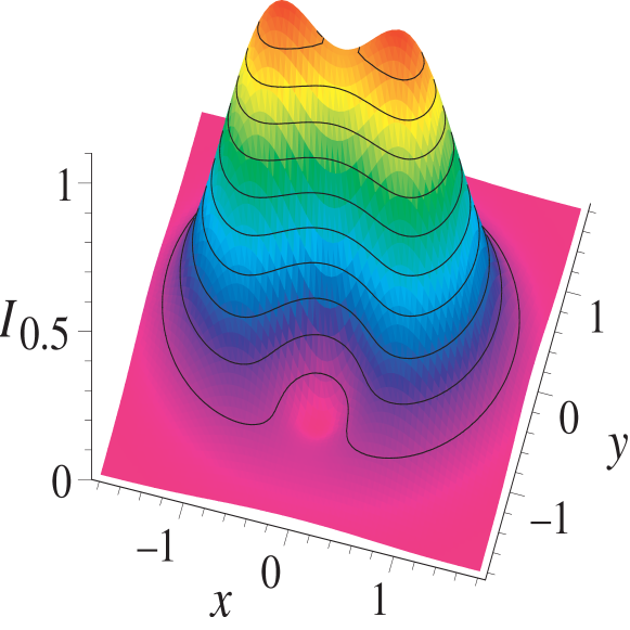
Bright and dark interference fringes extending across a standing wave’s cross-section are ubiquitous. In optics they have found applications in Lippmann’s photography and Gabor’s holography. They arise in laser cavities and interferometry and are used as transporters [16] and imaging elements [17] in atom optics. They are on the order of half a wavelength of the interfering light apart and since light beams are more than a wavelength wide and can overlap over considerable areas these bright fringes often resemble very tall stacks of pancakes [16]. They can also be slightly modified (the pancakes become deformed), due to the dispersive effects of Gouy’s phase, in interfering multimode beams [7]. Instead of using the superposition of identical beams we want to consider the interference between two monochromatic, collinear, counterpropagating partial waves with different orbital angular momenta [1, 2]. In this case one can imagine the pancakes (which are centered on the beam axis, compare Fig. 1 (a) top) to be cut open on one side, then splayed open and glued to the opposing cut faces of their neighbours, compare Fig. 1 (a) middle. In the most tightly wound case such a screw dislocation [15] yields a helix with pitch length , see Fig. 1.

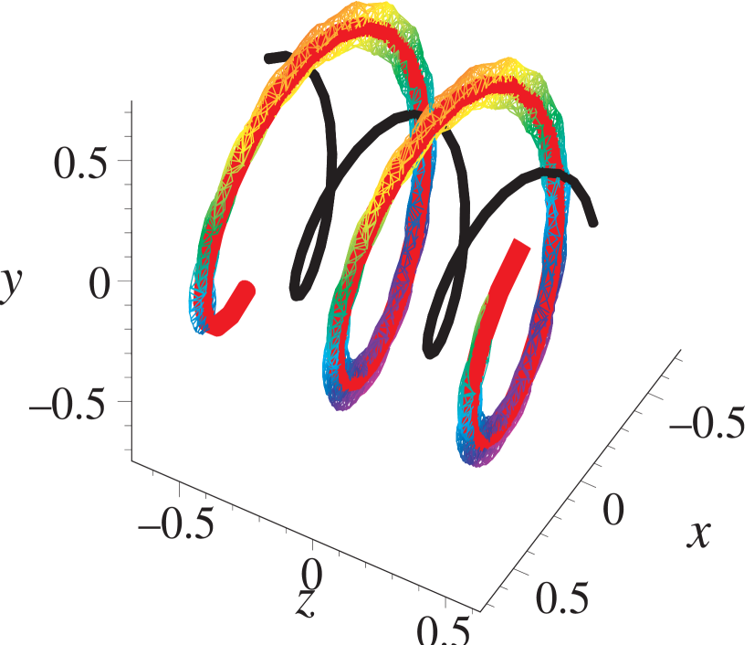
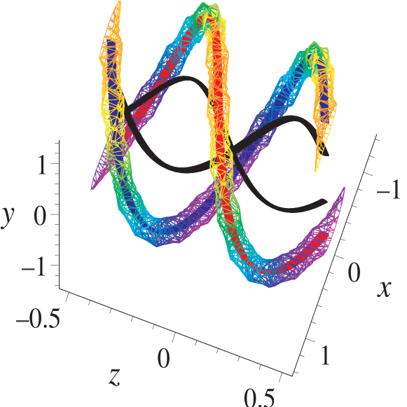
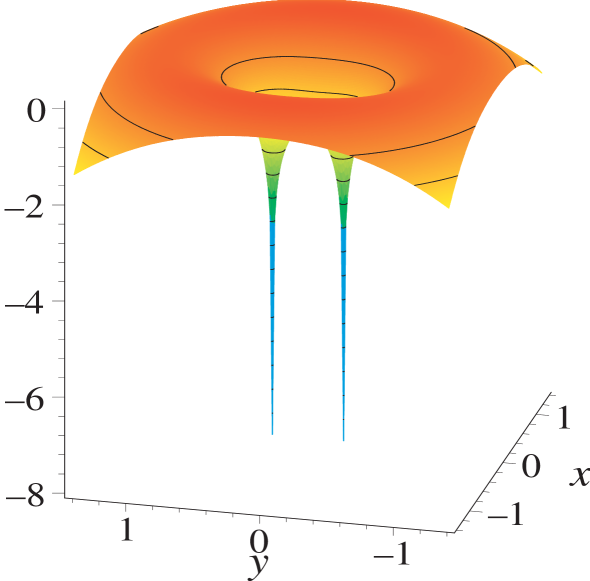
The common pancake stack scenario can be viewed as the special case of a degenerate helix with orbital angular momentum difference and associated pitch length . Alternatively to linking up nearest neighbours, the cut-open pancakes can be connected to their second nearest neighbour with pitch length leaving the nearest neighbour to form part of a second helix on the opposite side of the beam axis, compare Fig. 1 (a) bottom and Fig. 2.
In general the helices’ pitch lengths (orbital angular momentum quantization implies that is an integer [1]) are determined by the difference in orbital angular momentum of the used laser beams and obey . A negative helix length describes inverted handedness. Different superpositions can yield a larger number of intertwined helices and concentric shells of helices, compare Fig. 2. Per nodal shell, there tend to exist a number of separate bright helices with dark helically wound regions between them, see references [2, 3] and text following eq. (1) below. Details depend on the mode structures and relative weights of the employed superpositions, see sections 2 and 4.

The helices’ widths can be controlled through the width of the laser beams’ waists . Their lengths are practically limited by the laser beams’ divergence. If the beams’ cross-sections are elliptically deformed, so are the helices. Suitable laser beam modes that carry orbital angular momentum, such as Laguerre-Gauss–modes [1], are readily available [2, 3, 4, 5, 18] and the required superpositions are straightforward to implement [19]. The relative phases of the interfering beams can be shifted such that the intensity-helices revolve around their main axis (including very rapid rotations through frequency detuning between the two opposing beams [20, 18]).
For specificity, we will consider the paraxial Laguerre-Gauss modes [1, 21] (formed from ‘generalized Laguerre polynomials’ rather than, say, orbital angular momentum carrying Bessel-beams [12])
| (1) | |||||
Here is the laser’s wavelength and its wave number; and are the transverse coordinates, and parameterizes the beam axis. Kronecker’s -function takes care of the correct normalization. The azimuthal angle is connected to the transverse coordinates via the relation : is the integer orbital angular momentum index with the associated orbital angular momentum [1, 2]. The discrete radial index counts the number of nodal rings in the radial direction . The beam radii are given by with the beam waist radius where is the Rayleigh-length which also parameterizes the Gouy-phase shifts and the wavefront radii [1, 21].
In order to form bright (or dark) light helices we have to create constructive (or destructive) interference along the entire phase front. For this it suffices to interfere two radially matching pure Laguerre-Gauss laser modes, with suitably chosen amplitudes and , travelling in opposite directions, namely, to form a superposition
| (2) |
where we used for the angular frequency of the light and the paraxial solutions
| (3) |
We assume that the laser is uniformly polarized and the wave front curvatures can be neglected. Thus the electric field is a scalar field multiplied with the polarization vector [22]. From this superposition we can extract the spatially fast-oscillating term which yields the interference term . When a full turn () along the intensity helix is tracked the ensuing spatial shift yields the pitch length in the -direction
| (4) |
This confirms the intuitive description in terms of a screw dislocation given above. Note that the interference between two beams travelling in the same direction yields interference fringes [4] but not helical intensity spirals on the wavelength scale; instead it forms intensity rods which are modulated by Gouy’s phase thus forming rods with a twist [23, 8], very similar to those displayed in Fig. 1 of reference [24].
Intuitively, this should not be too surprising since in a forward-only configuration light following a helical path would travel superluminally. The effects discussed here are not a consequence of Gouy’s phase, unlike the helical intensity distributions considered in references [8] and [25] or the nodal lines investigated in reference [19], all giving rise to ‘half-oscillations’ [7] on the scale of the beam’s Rayleigh length.
The effects discussed here necessarily require interference of two counterpropagating partial waves; this implies that the medium needs to be sufficiently transparent. Also note that reflection by a mirror inverts the helicity of a mode and therefore beams carrying orbital angular momentum, say within a laser cavity, form intensity helices (but not single standalone helices since in the reflection case).
3 Some features of single dark helix beams
In this section some features of the single-helix superposition
| (5) |
of an ordinary Gaussian beam with a counterpropagating Laguerre-Gauss mode with one unit of orbital angular momentum are elucidated.
The single-helix superposition forms a single bright and a single dark helix, the Gaussian beam’s relative weight fixes the dark helix’ radius since the field’s zero in the focal plane occurs at . The stronger the field of the added Gaussian beam the more the zero of the Laguerre-Gaussian mode gets displaced from the beam axis, compare Figs. 2 and 4. For small values of the coefficient the dark helices are slim and steep, yet, unlike bright helices they remain distinguishable, see Fig. 4.
In general, determination of the precise form of helices along the beam axis requires solving an implicit problem. For beams formed from superpositions of the form (2) (of which of eq. (5) is a special case) the following mapping allows for a quick determination of the approximate location of the helices.
| (6) | ||||
| (7) |
This is to be read as a complex-plane representation of a mapping of a helix’ focal plane location to its location along the beam axis.
Next we determine the field gradients for a dark helix formed from a single-helix beam at the intensity zero in the focal plane
| (8) | ||||
| (9) | ||||
| (10) |
here, the complex phases represent the gradients’ phase differences within the optical cycle. The gradients can be used to derive the exact pitch angle the helix forms with the focal plane
| (11) |
In this derivation the first step arises from the observation that since the helix passes through its tangent vector has the form . Since the helix is dark it moreover fulfils the condition which implies eq. (11) above. For large values of and this expression conforms with the ‘naive’ expectation .
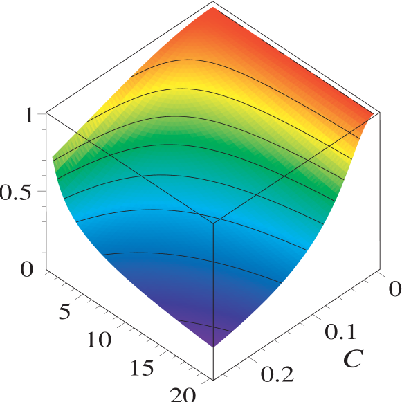
With the abbreviation , we can write down the normalized focal tangent vector and complete the associated Frenet trihedron by forming the third vector .
A dark helix can be used as the core of a blue-detuned [26], helical atom waveguide [14]. Whereas points in the direction of free movement, and form the principal axes of the local transverse trapping potential
| (12) | ||||
| (13) |
This can be used to determine the transverse potential’s trapping frequencies and their anisotropy ratio [14], which is plotted in Fig. 3.
4 Dark helices are more sharply contoured than bright helices
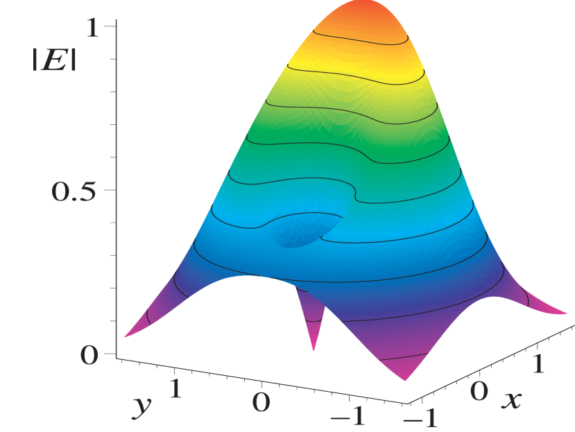
Unlike bright features dark features can provide superresolution [27]. This allows us to create structures with spatial extensions below the diffraction limit. To see how the optical resolution limit constrains bright helices much more than dark ones, recall that bright helices are centered on the maximum position of the local electric field. According to Fourier’s theorems monochromatic light fields in free space have to be smooth and differentiable, they cannot have spikes. Therefore, the field’s magnitude, when moving by a small displacement away from the core of the helix, can at best drop quadratically with , namely, with as the maximal local curvature we have
| (14) |
Around a zero at location the field instead typically rises linearly (unless one tracks the helix core), this variation is bounded by the largest local gradient
| (15) |
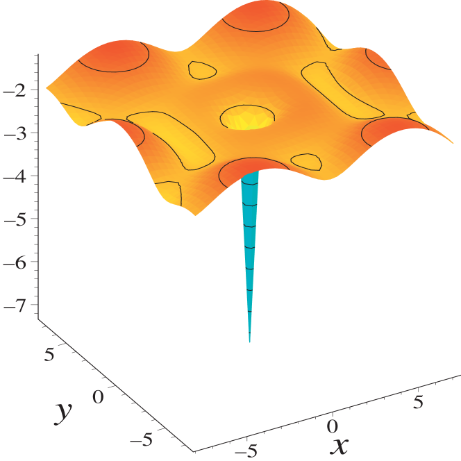
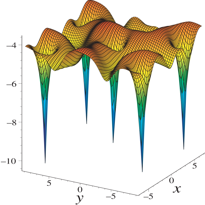
This difference in the scaling of the variation of the local field magnitude allows for sharper definition of dark helices compared with bright ones; this is represented graphically in the field magnitude plot of panel (c) of Fig. 1, in the comparison in Fig. 4, and in the ‘spikiness’ of the dark helices’ intensity profiles in Fig. 5 (b) and (c). Note that the location of the bright helices in these two plots are harder to make out than those of the dark ones. One might be tempted to argue that a logarithmic plot ‘unfairly’ pronounces the presence of dark helices over bright ones, but photoresists, for example, tend to have logarithmic response functions [28] so the use of Figs. 4 (b), and 5 (b) and (c) is quite suitable when trying to gauge outcomes in a photo-lithographic application.

5 Lattices of dark helices
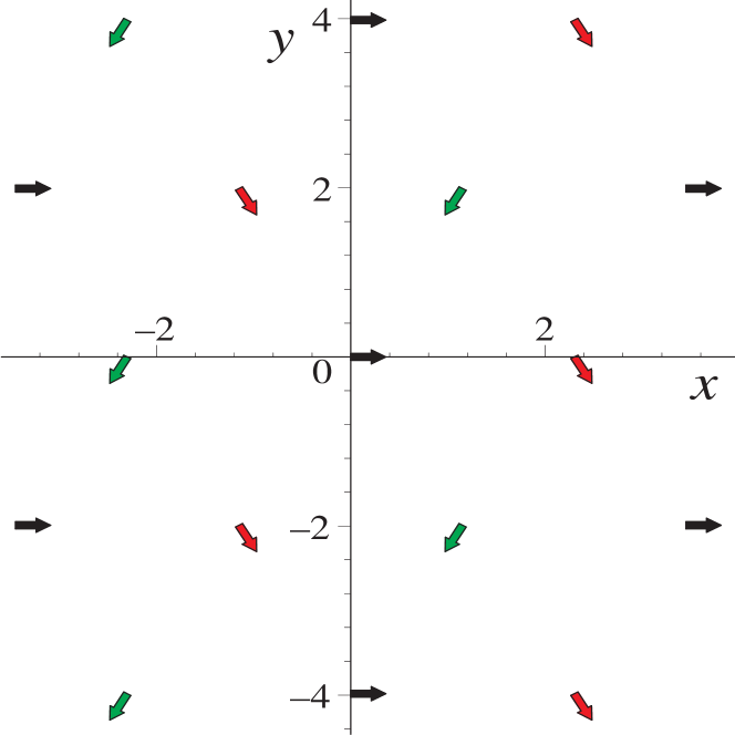
It is possible to embed dark helical beams into a background of roughly uniform illumination. To this end a hexagonal lattice is used because it has high symmetry and can be very tightly packed. Ordinarily, regions of completely destructive interference of such tightly packed beams would be unavoidable. In order to make certain that no dark areas other than the desired dark helices are created, we partition the lattice into three triangular sub-lattices with different polarization directions, see colour-coding of Fig. 5 (a). In our examples, the hexagonal lattice is either filled with ordinary Gaussian -beams, Fig. 5 (b), or with single-helix beams , see Fig. 5 (c); one of which is displayed in Fig. 5 (d).
In case 5 (b), the lattice beam at the origin (black arrow) is removed, a very weak -polarized beam is superimposed to remove spill-over from the nearest neighbours and a single-helix beam inserted at the origin. This construction demonstrates that a single dark helix can be embedded into a bright uniform background. Alternatively, the entire lattice is formed from helical beams with equal strength, see Fig. 5 (c); where, on account of the slightly wider lattice spacing, no spill-over compensation is applied.
The logarithmic intensity plots 5 (b) and (c) confirm that the background intensity is quite uniform (varies less than an order of magnitude) and yet allows for embedded dark spirals with excellent intensity contrast: the helix cores are at least four orders of magnitude darker than the background.
6 Applications, conclusions and outlook
The generation of bright and dark intensity helices from paraxial laser beams was studied. Such intensity helices of light may turn out to be applied in nanolithography of bulk media [29] to create sharply contoured helical imprints in potentially massively parallel fashion.
In section 4 the variation of the electric field magnitude in the immediate vicinity of intensity helices was characterized. This variation scales linearly for dark and quadratically for bright helices.
The very much sharper intensity contrasts this scaling implies for dark helices may turn out to be of considerable practical importance. The logarithmic intensity plots of Fig. 5 (b) and (c) show that we can create sharp spikes of the intensity distribution of dark helices whereas this is impossible for bright helices. This observation is relevant for lithographic applications because photoresists tend to show logarithmic responses to the magnitude of the irradiating field [28].
In order to demonstrate the versatility of the approach presented here it was shown that single dark helices can be sparsely embedded in a uniform bright background but also tightly packed into a dense hexagonal grid embedded in a uniform bright background.
The intensity helices’ defined handedness might, for example, help with the production of chiral optical meta-materials [30, 31], possibly using longer wavelengths such as from THz-radiation [32].
Filtering of handed molecules, through a membrane with photo-lithographically etched helical holes or via handedness-sensitive trapping in solution, might become possible.
For the manipulation of ultra-cold gas clouds via the optical dipole force, dark (blue-detuned) and bright (red-detuned [14]) helical beams may turn out to be useful [26].
The fact that helices can be made to intertwine, see section 2, opens up the possibility of studying intertwined transport. In the presence of gravity or other uniform force fields a helix that is tilted away from vertical by more than its pitch angle can potentially serve as a microscopic Archimedean-screw transporter [16] or a helical ratchet-potential. Transport along helices is expected to show localization behaviour [33, 34] and other interesting quantum-transport phenomena [35].
Acknowledgment
I would like to thank Paul Kaye for proof-reading of this manuscript.