A gradient-augmented level set method with an optimally local, coherent advection scheme
Abstract.
The level set approach represents surfaces implicitly, and advects them by evolving a level set function, which is numerically defined on an Eulerian grid. Here we present an approach that augments the level set function values by gradient information, and evolves both quantities in a fully coupled fashion. This maintains the coherence between function values and derivatives, while exploiting the extra information carried by the derivatives. The method is of comparable quality to WENO schemes, but with optimally local stencils (performing updates in time by using information from only a single adjacent grid cell). In addition, structures smaller than the grid size can be located and tracked, and the extra derivative information can be employed to obtain simple and accurate approximations to the curvature. We analyze the accuracy and the stability of the new scheme, and perform benchmark tests.
Key words and phrases:
level set method, subgrid resolution, CIR-method, cubic, curvature2000 Mathematics Subject Classification:
65M25; 35L651. Introduction
Level set methods represent a surface as the zero contour of a level set function [14], which can be numerically defined on a regular Eulerian grid. The advection of the surface translates then into an appropriate advection of the level set function. Derivative quantities, such as normal vectors and curvature, can be computed from the level set function without explicitly representing the surface. Commonly used level set approaches encounter problems or inconveniences in the following aspects: the representation of small structures, the approximation of derivative quantities (such as curvature), and the large size of the stencils required by high order finite difference schemes.
We investigate the extent to which these problems can be remedied, if the level set function is augmented by gradient information. In this case, the surface can be represented by an appropriate interpolation that incorporates the additional information. In this paper, we consider a bi-/tri-cubic Hermite interpolation to define the surface in each cell. This yields a certain level of “subgrid” resolution, i.e. structures smaller than the grid resolution can be represented. In addition, the Hermite bi-/tri-cubic interpolant provides a simple and accurate approximation to the normals and the curvature anywhere in the computational domain. In the context of level set methods, the use of a bicubic interpolation to construct second order approximations to interfaces was proposed by Chopp [3], but without any tracking of gradient information.
The idea of using gradient information to improve the accuracy of numerical methods for hyperbolic conservation laws was introduced by van Leer [23, 24, 25, 26, 27]. In particular, his MUSCL (“Monotonic Upstream-centered Scheme for Conservation Laws”) scheme and the PPM (“Piecewise Parabolic Method”) by Colella and Woodward [4] use gradient information. While in those methods, gradient values are reconstructed from function values, the CIP method of Takewaki, Nishiguchi, and Yabe [21, 22] stores gradients as an independent quantity to solve hyperbolic conservation laws. In the context of level set methods, Raessi, Mostaghimi, and Bussmann present an approach that advects normal vectors independent of, but in an analogous fashion to, the level set function values [15].
In this paper, we present an approach that advects function values and gradients as independent quantities, but in a fully coupled fashion. The approach is based on a generalization of the CIR method [5], and uses the Hermite cubic interpolant mentioned above in a natural way. Characteristic curves are tracked backwards, and function values and gradients are obtained from the interpolation. The resulting advection scheme is globally third order accurate, with stencils that can be chosen no wider than a single cell.
In Sect. 2, we provide a brief overview of the classical level set method, introduce the idea of gradient-augmented approaches, and present a Hermite cubic interpolation that will be the basis for the new method. Three fundamental problems with classical level set methods are outlined in Sect. 3, with focus on how the incorporation of gradients is beneficial. The precise numerical scheme is given in Sect. 4. Its accuracy and stability are analyzed theoretically in Sect. 5, for a simple case. In Sect. 6, we numerically investigate the accuracy of the new approach, and test its performance on various benchmark tests. Finally, in Sect. 7, we outline various questions to be investigated in future work.
2. Level Set Approaches Without and With Gradients
2.1. Classical Level Set Method
Many applications, such as the simulation of two-phase flows in require the representation and advection of a manifold of codimension 1, which in the following we call a surface. Level set methods [14] represent the surface as the zero contour of a level set function . In the domain enclosed by the surface, one has , while outside . Geometric quantities, such as normal vectors and curvature, can be obtained from the level set function: , and . In order to move the surface with a velocity field , the level set function is advected according to the partial differential equation
| (1) |
The level set function can be defined on a regular grid. High order ENO [17] or WENO [10] schemes are commonly used to approximate the advection equation (1).
Gradients and curvatures can be approximated by finite differences. For an accurate and stable approximation, it is beneficial if is a signed distance function
| (2) |
Even if is a distance function initially, it typically ceases to be so due to deformations induced by the velocity field. One remedy to this problem is to recover (2) by solving the reinitialization equation
| (3) |
where is the level set function at time , in pseudo-time [20], or by solving the stationary Eikonal equation (2) using a fast marching method [16]. Another approach is to solve (1) with a modified velocity field, so that (2) is preserved. This modified field is constructed by extending the original velocity field away from the surface [1].
The actual surface is obtained from the level set function using contouring algorithms [11]. These approaches are typically based on a bi-/tri-linear interpolation inside a grid cell. The linear interpolant along cell edges locates intersections of the surface with the grid edges. These intersection points are subsequently connected to form surface patches in each cell. Ambiguous connection cases are decided based on the full bi-/tri-linear interpolant inside the cell. In many applications, it is sufficient to know the location of the surface on the grid edges, for instance in the ghost fluid method [7].
2.2. Gradient-Augmented Level Set Method
We consider a generalized level set approach. The level set function is augmented by gradient information , which is defined on the same grid as . The surface is defined using both independent quantities and . This approach has various advantages in the context of level set methods. Raessi et al. show that under some circumstances, curvature can be computed more accurately if gradients are accessible [15]. In addition, as we show in the following, with gradients, subgrid structures can be represented, and a high order advection scheme with optimally local stencils can be formulated.
Evolving the implicitly defined surface with a velocity field translates to equation (1) for , and equation
| (4) |
for . Equation (4) is obtained by applying the gradient operator to (1). A straightforward approach is to approximate each equation (1) and (4) using a high order finite difference scheme. Raessi et al. apply this approach [15], introducing only a weak coupling through an extension velocity field [1]. While such decoupled (or weakly coupled) approaches can improve the classical level set approach, the full potential of a coupled approach is not used. In contrast, here we present an approach that evolves the level set function and its gradients in a coherent and fully coupled fashion. The precise methodology is presented in Sect. 4.
2.3. Cell-Based Hermite Interpolant
In the gradient-augmented level set method, every grid point carries a function value and a gradient vector. Thus, in space dimensions, every grid cell has pieces of information on each of the cell corner points. As we show, this allows the definition of a cell-based Hermite interpolant, i.e. a function that is inside each cell, and that matches the function values and gradients at all cell corner points. In this paper, we consider a -cubic Hermite interpolant, i.e. a cubic in 1D, a bi-cubic in 2D, a tri-cubic in 3D, etc. It is a natural generalization of the bi-/tri-linear interpolation used in classical level set approaches. The interpolant is simple to construct, using a tensor product approach.
In the following, we use the classical multi-index notation. For vectors and , one defines , and , and , where . For convenience, we formulate some results for cubes, for which denotes the edge length . However, the results apply to rectangular cells of arbitrary edge lengths as well. In this case, the estimates are valid with respect to the scaling parameter .
Definition 1.
A -cubic polynomial is a polynomial in , of degree in each of the variables. Hence, it has an expression of the form
involving parameters .
Definition 2.
A -rectangle (or simply “cell”) is a set , where . If , we speak of a -cube (of size ), denoted by . The -cube is called unit -cube.
Let the vertices in a cell be indexed by a vector , i.e. the vertex of index is at position . In particular, for , we have .
Definition 3.
Let be a -rectangle, and let be a sufficiently smooth function defined on an open set in that includes . The data for on is the set of scalars given by
where both .
Lemma 1.
Two -cubic polynomials with the same data on some -rectangle, must be equal.
Proof.
WLOG assume that the -rectangle is the unit -cube . Let be the difference between the two polynomials—with zero data on . We show now that .
-
(1)
If , is a cubic polynomial in one variable, with double zeros at . Hence .
-
(2)
If , the result yields . Hence, the same argument as in yields: .
-
(3)
If , the result yields . As before, it follows that from the result that .
From the above, it should now be obvious how to complete the proof using induction on . ∎
Theorem 2.
For any arbitrary data set on some -rectangle, there exists exactly one -cubic polynomial which corresponds to the data.
Proof.
Lemma 1 shows that there exists at most one such polynomial. Here we construct one. WLOG assume that the -rectangle is the unit -cube . For each vertex of , indexed by , and each derivative , one can construct Lagrange basis polynomials , i.e. -cubic polynomials that satisfy
Here , where is Kronecker’s delta. Hence, each of the basis polynomials equals 1 on exactly one vertex and for exactly one type of derivative, and equals 0 for any other vertex or derivative.
The basis polynomials can be constructed as tensor products of the form
where each of the is a -cubic polynomial
| (5) |
where and .
A -cubic that corresponds to the data, is then defined by a linear combination of the basis functions
| (6) |
∎
We now investigate how well the -cubic (6) approximates a smooth function, when interpolating it on the vertices of a cell. We are interested in its accuracy, as the cell size approaches zero. While the following analysis also holds for -rectangles, for simplicity (and WLOG), we provide the expressions for -cubes only.
Definition 4.
Consider a (sufficiently smooth) scalar function , defined in an open neighborhood of the origin in . Let be small enough so that the -cube is included in . The -cubic Hermite interpolant to in is the -cubic polynomial , such that and have the same data on .
Using the notation of Def. 3, and equation (6), it is easy to see that the -cubic Hermite interpolant in Def. 4 can be written in the form
| (7) |
This expression is straightforward to differentiate analytically: derivatives of the -cubic basis functions (5), and powers of , appear.
Example 1 (1D Hermite cubic interpolant).
On a 1D cell of size , with grid values denoted by , and derivatives by , the Hermite cubic interpolant is defined by
| (8) |
and its derivative is
| (9) |
where we use the relative coordinate .
Remark 1.
The 1D Hermite cubic (8) is the unique minimizer of the functional under the constraints that the function values and derivatives are matched at and . This is a standard problem in calculus of variations. The cubic (8) is a minimizer, since it solves the corresponding Euler-Lagrange equation . It is the unique minimizer, since is convex, and the domain for the minimization problem is also convex. Thus, the 1D Hermite cubic minimizes the norm of the second derivative.
Lemma 3.
Theorem 4.
Let and be as in Def. 4. Then, for any point in , we have
| (10) |
where the coefficients in the error terms can be bounded by some constant multiple of the norm in .
Proof.
Lemma 3 and Thm. 4 imply that the -cubic interpolant is fourth order accurate, if any required derivative is known with accuracy on the cell vertices. Since in a gradient-augmented method, we only assume that the function values () and the gradients () are given, we need to construct any required cross derivatives () with accuracy , from the given data. Interestingly, this means that one can set to zero all the derivatives of order higher than 3, without affecting the interpolant’s accuracy. Unfortunately, this convenience does not come into play for dimensions .
The cross derivatives required by (7) can be constructed to the appropriate order from the function values and the derivatives at the grid points. Two possible approaches are:
-
(A)
Central differencing. Second order cross derivatives can be approximated by central differences of neighboring points, such as (here written for on a cell of size , all proportional to )
By construction, these approximations are second order accurate. The third order cross derivative can be approximated by
This approach defines one unique value for each required cross derivative at each grid point. Hence, the thus defined -cubic interpolant is across cell edges. A technical disadvantage is that the optimal locality is to a certain extent lost: The interpolation in a cell uses information from adjacent cells corner points.
-
(B)
Cell-based approach. In 2D, a second order accurate approximation to the second order cross derivatives at the vertices of a cell can be obtained from the gradient values at the vertices in the same cell, using finite differences and interpolation/extrapolation:
-
(1)
The central differences , , , approximate at the cell edge centers.
-
(2)
Weighted averages of these values yield approximations to at the cell vertices. The weights follow from bilinear interpolation, and are for the two nearby edge centers, and for the two opposing edge centers.
To obtain the cross derivatives in 3D, the formulas above are applied in a facet of the 3D cell.
A first order accurate approximation to the third cross derivative is given by
This approach is purely cell-based, and the interpolation can be implemented as a single black-box routine. A technical disadvantage of this approach is that one and the same grid point is assigned different cross derivative values, depending on which cell it is a vertex of. Since the approximations are second order accurate, the various cross derivatives at a grid point differ by . Consequently, the resulting -cubic interpolant is continuous, but the gradient jumps across cell edges, with discontinuities of size .
-
(1)
In practice, both approaches perform well. Note that above approximations are just one possible way to approximate the cross derivatives. The final method proves rather robust with respect to the actual approximation chosen. In fact, even if an error is done in the cross derivatives (e.g. by setting them equal to zero), the method remains convergent, though with a lower order of accuracy.
3. Benefits of Incorporating Gradient Information
While the classical level set method, outlined in Sect. 2.1, is a powerful tool in representing and advecting surfaces, it suffers from some problems and inconveniences. In this paper, we address three fundamental aspects, and show how a gradient-augmented approach, as outlined in Sect. 2.2, can ameliorate them:
-
•
Small structures are lost once below the grid resolution. Gradients yield a certain level of subgrid resolution (Sect. 3.1).
-
•
An accurate approximation of the curvature involves difficulties. With gradients, surface normals and curvature can be easily obtained from the -cubic Hermite interpolation (Sect. 3.2).
- •
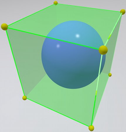
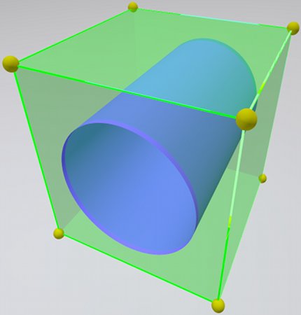
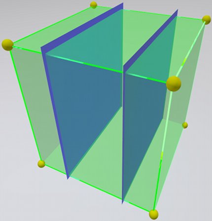
3.1. Representation of Structures of Subgrid Size
Structures that are at least a few cells wide are represented well by the classical level set method. However, smaller structures are only represented if they contain grid points. This leads to the inconsistency that one and the same small structure can be present (if a grid point happens to fall into it) or be missing (if it happens to fall in between grid points). Furthermore, even if initially present, small structures may vanish over the course of a computation due to approximation errors in the numerical scheme, such as numerical diffusion or dispersion. Small drops, jets or films (see Fig. 1) may be lost during a computation, resulting in a “loss of volume”. Other difficulties are the numerical coalescence of nearby structures, or a numerical pinch-off in a thinning process. In practice, the loss of small structures can be prevented using adaptive mesh refinement (AMR) techniques [18, 12], which add a significant level of complexity, especially when high order approximations need to be preserved across multiple levels of refinement. The problem of volume loss can be addressed by enforcing conservation of volume, as proposed by Sussman and Fatemi [19]. Such methods guarantee conservation of volume (up to a small approximation error), but may yield incorrect topologies. An alternative approach is to augment the level set function by Lagrangian particles, as proposed by Enright, Fedkiw, Ferziger, and Mitchell [6]. This latter method resolves the difficulties described above in a satisfactory manner, but at the expense of simplicity.
Fig. 2 shows a signed distance level set function (solid line) of a 1D “bubble” between two grid points. Classical level set methods use a linear interpolation (dashed line). Hence, no structure is identified, since the level set function has equal sign on the two grid points. Of course, the same structure would be identified if a grid point fell within it, but it would be lost when advected into the situation shown in Fig. 2. Also, if one knows that is a signed distance function, the surface can be identified, as shown by Chopp [3]. Unfortunately, this approach incurs difficulties in higher space dimensions, where ambiguities arise. In addition, the assumption of having a precise signed distance function is too limiting in many cases.
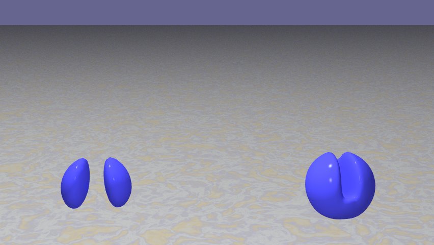
A gradient-augmented level set approach allows the representation of a full structure, i.e. two surfaces, between two neighboring grid points. Fig. 2 shows a cubic interpolant (dash-dotted line) along a cell edge, constructed from the correct function values and gradients. In fact, a subgrid structure is detected. Similarly, with bi-/tri-cubics, subgrid structures in 2D and 3D can be approximately represented. Each subgrid structure shown in Fig. 1 is defined by a tri-cubic, as follows. For a cube of size , we consider the function values on the vertices . The drop (sphere) is then obtained by providing gradients . The jet (cylinder) is obtained by . And the film (two planes) is obtained by .
At the same time, the example in Fig. 2 indicates a major drawback of -cubic approaches: Level set functions are typically non-smooth (e.g. signed distance functions). Hermite -cubics are smooth, hence the approximation is not very accurate near kinks. As a result, even with -cubic approaches, smaller structures may vanish eventually, though significantly later than with classical level set methods. A potential remedy can be to use higher order, or nonlinear interpolations, which we shall investigate in future work.

Theoretically, the gradient-augmented level set approach allows the representation of (at least some) isolated structures of arbitrarily small size. Hence, the use of gradient information is more than a mere increase of resolution. Of course, in practice there are limitations to the size of the small structures that can be represented reliably. In addition, only isolated subgrid structures can be represented. The structure shown in Fig. 2 is indistinguishable from two small structures in the cell, whose outer boundaries are at the same positions as the boundaries of the single structure.
3.2. Approximation of Derivative Quantities
In many applications (e.g. in two-phase flow simulations with surface tension), normal vectors and curvatures are required. In terms of the first and second derivatives of the level set function , the expressions are (here in 2D)
| (11) | ||||
| (12) |
In classical level set methods, the required derivatives , , , , are typically obtained from by central differences. Assuming that the level set function is known with fourth order accuracy on the grid points, second order accurate approximations to normals and curvature on the grid points are obtained from the expressions (11) and (12).
Away from grid points (such as it is required by the ghost fluid method), second order accurate approximations can be obtained by using weighted averages. Several problems with computing curvature from level set (and volume of fluid) functions, in particular in connection with reinitialization (3), have been presented by Raessi et al. [15]. In addition, even if a suitably high order advection scheme is used, under various circumstances the level set function values can cease to be fourth order accurate. For instance, when a WENO stencil crosses a discontinuity in the gradient (e.g. signed distance level set functions (2) possess discontinuous derivatives), the accuracy of the approximation can drop [10].
Gradient-augmented level set methods offer new possibilities in the approximation of derivative quantities. For instance, the -cubic Hermite interpolation considered here gives rise to a particularly simple way to obtain normals and curvatures at arbitrary points. Inside each cell, all first and second derivatives can be obtained analytically by differentiating the interpolant (7). Normal vectors and curvature are then simply obtained by (11), respectively (12). Due to Thm. 4, first derivatives are third order accurate, and so is the obtained . Further, second derivatives are second order accurate, and so is the obtained . The numerical results shown in Sect. 6.1.3 verify this. Hence, using the Hermite -cubic, derivative quantities (of up to second order) can be obtained everywhere with at least second order accuracy, by a simple recipe with optimally local stencils, i.e. they use information only from a single cell.
3.3. Coherent Advection with Optimally Local Stencils
In order to both accurately advect structures, and calculate derivative quantities, high order schemes have to be used. In classical approaches, the stencils for high order schemes reach over multiple cells. This results in a cumbersome implementation on adaptive grids and near boundaries.
In Sect. 4, we present a semi-Lagrangian approach that solves the advection problem with third order accuracy. The characteristic form of the equations (1) and (4) is used to update the function values and gradients at the grid points. In each time step, the characteristics are traced backwards from the grid points, and function values and gradients on the characteristic, at the prior time step, are extracted from the Hermite interpolant, as defined in Sect. 2.3. A key advantage of this approach is that at each grid point, the data is updated using only information from a single adjacent cell. Hence, the gradient-augmented approach delivers a high order advection with optimally local stencils. It seems evident that the optimal locality should allow a simple treatment when combined with adaptive mesh refinement and near boundaries. The detailed investigation of this matter is left for future work.
4. Numerical Methodology of the Generalized CIR Scheme
We consider the linear advection equation (1) with . The evolution of the level set function and its gradient, given by (1) and (4) can be rewritten as
| (13) |
For functions defined everywhere, the evolution for is completely determined by . However, for functions known only on grid points, the gradients carry additional information that is not encoded in . For the moment, we assume the velocity field , and the velocity deformation matrix
to be exactly accessible everywhere. The system (13) consists of an advection part (left hand side), and a source term for . Its characteristic form is
| (14) |
This system of ODE describes the evolution of and along the characteristic curves defined by . We solve these equations by a generalization of the CIR method by Courant, Isaacson, and Rees [5]: the characteristics (14) are traced backwards from the grid points, and the required data is obtained by the interpolation. Note that, while the CIR method is, in general, non-conservative for nonlinear conservation laws, its use is justified here, since equations (1) and (4) are linear.
Let , denote the data at time , and , denote the data at time . We find the characteristic curves that pass through grid points at time , and solve (14) along these characteristic curves. One time step of the scheme from to reads as follows:
-
(1)
For each grid point , solve the characteristic equation
(15) backwards from to , to find the point . The characteristic curve that passes through at time , reaches at time .
-
(2)
Assign and , both evaluated analytically from the Hermite interpolation (7) in the cell that falls into.
- (3)
In principle, there is no requirement for the backward characteristic curves to remain in a single cell, as long as the integration scheme for (15) is accurate enough to prevent the approximate backwards characteristic curves from intersecting (which may cause oscillations). However, in practice, it is often convenient, and not too restrictive, to choose , where is the maximum magnitude of , and is the grid size. This guarantees that characteristic curves from different grid points do not intersect, and that characteristic curves do not cross multiple cells.
As proved in Thm. 4, the interpolation approximates with fourth order accuracy and with third order accuracy. Therefore, in order to achieve the maximum possible order of accuracy, the backwards characteristics equation (15) needs to be solved with fourth order accuracy in each time step.111This then yields a globally third order in time algorithm, see Sect. 5.5. One step of the Shu-Osher RK3 method [17] does the job. Since gradients are generally one order less accurate, their evolution equation (16) needs to be solved with third order accuracy. One step of Heun’s RK2 method (explicit trapezoidal) does the job. However, in Sect. 5 we outline another possibility, which is to systematically inherit the update rule for (16) from the scheme used for (15). We also investigate the accuracy and stability of the gradient-augmented scheme.
In one space dimension, for constant velocity fields, the presented approach is equivalent to the CIP method [21, 22], which also uses a -cubic interpolant. Note that the presented gradient-augmented level set approach is not limited to -cubic interpolants. Within the setting of superconsistency, introduced in Sect. 5.1, the projection step, defined in Sect. 5.2, can be replaced by other forms of projection (see Rem. 2).
The gradient-augmented level set method is not a finite difference method, since differential operators are not approximated. Instead, fundamental properties of the exact solution to the underlying equation are used, and derivatives are evaluated analytically from the interpolation patch. The approach is based on local basis functions, as a finite element method is. However, the update rule is very different than for classical finite element approaches.
The generalized CIR approach is cell-based, thus preserving the benefits of the level set method, such as handling of topology changes, parallelizability, etc. In addition, it is optimally local: The new data values at a grid point use only information from corner points of a single adjacent cell. Compared to WENO schemes, which use information multiple cells away, the CIR method promises an easier treatment of approximations on locally refined meshes and near domain boundaries. In addition, the locality allows smaller structures to get close together without spoiling the accuracy of the approximation.
4.1. Boundary Conditions
When solving the linear advection equation (1) on a domain with outward normals , boundary conditions have to be prescribed wherever the flow enters the domain, i.e. . The accurate treatment of boundary conditions is a common challenge in high order methods. For level set methods, this is important whenever the interface is close to the boundary. In WENO methods, ghost points have to be created using appropriate extrapolations. Since WENO stencils reach over multiple cells, not only do inflow boundaries pose a challenge, but also outflow boundaries, at which the actual equation does not require any boundary conditions.
In contrast, the gradient-augmented CIR method presented above, treats outflow boundaries naturally: no information has to be prescribed, since characteristics come from inside the domain. At inflow boundaries, information for both and has to be prescribed. Below we give two illustrative examples that show how to create the required information from the advection equation (1), for the two most common types of boundary conditions. Other types of boundary conditions can be treated similarly.
Consider a domain boundary that is aligned with cell edges. WLOG assume that this boundary is perpendicular to . Then
-
•
Dirichlet boundary conditions prescribe on the boundary, which is perpendicular to . Therefore, all partial derivatives perpendicular to , i.e. and , as well as , are prescribed as well. The missing derivative on the boundary follows from the equation (1) as
Note that , since .
-
•
Neumann boundary conditions prescribe on the boundary. Thus equation (1) yields a linear advection equation on the boundary
(17) with initial conditions given by the values of on the boundary at . Equation (17) can again be solved using the gradient-augmented CIR scheme. This yields the function values and the derivatives perpendicular to , i.e. and .
5. Analysis of the Gradient-Augmented CIR Method
Consider the numerical scheme presented in Sect. 4, for the linear advection equation (1), with given. Let be the solution to the characteristic equations (14), defined by
| (18) |
The solution operator to the linear advection equation (1) is then
| (19) |
Now consider a numerical approximation to , as arising from a numerical ODE solver, e.g. a Runge-Kutta scheme. Let the corresponding approximate solution operator to (1) be denoted by
| (20) |
5.1. Superconsistency
Equation (19) provides the exactly evolved solution, while equation (20) defines an approximately evolved solution, both at every point in the computational domain. In the actual numerical method, we consider only the (approximate) characteristic curves that go through the grid points at time . However, we can use the solution operator (20) to derive a natural update rule for the gradients. The gradient of the approximately advected function is
| (21) |
which yields the update rule for approximate function values and gradients
| (22) |
Definition 5.
We call a gradient-augmented scheme superconsistent, if it satisfies (22).
Example 2.
Using forward Euler to approximate (18) yields the superconsistent scheme
While this scheme is particularly simple, it is only first order accurate. A globally third order accurate scheme is obtained when using a third order Runge-Kutta scheme, such as in the following example.
Of course, it is not necessary to use a superconsistent scheme to update . In fact, other schemes to approximate (4) might be more accurate and/or more efficient. However, superconsistent schemes have the advantage that the gradients are evolved exactly as if the function values were evolved everywhere, and then the gradients were obtained by differentiating the function. This increases the coherence between function values and derivatives. In addition, superconsistent schemes can be analyzed in function spaces, without actually having to consider an evolution for the gradient.
5.2. Projection
The update rule (22) uses the function values and the gradients at for each grid point . The point is in general not a grid point. Hence, in the gradient-augmented numerical scheme, and are defined by the Hermite interpolation. Each time step of a superconsistent gradient-augmented scheme can be interpreted (in a function space) as an approximate advection step, followed by a projection step
At time , the level set function is represented by the cell-based -cubic interpolant approximation. This function is then advanced in time to by the approximate advection operator . Then a new representation in terms of cell-based -cubic interpolants is obtained by the projection operator , which uses the function and gradient values of the advected function at the grid points.
In this paper, the projection is given by the -cubic Hermite interpolant defined in equation (7), with the proviso that the required cross derivatives that appear in (7) are obtained by one of the (various possible) finite differentiation schemes described in Sect. 2.3.
In general, the operator alone is a much better approximation to than the combined . However, the projection step is required to be able to represent the numerical approximation to , at a given instance in time, by a finite amount of data. For the choice of used in this paper, a function is uniquely defined by the function values and gradient values on the grid points . Hence, in the numerical scheme, the advection operator has to be evaluated only along the characteristic curves that go through the grid points, using only the function values and derivatives there.
Remark 2.
In principle, the presented generalized CIR algorithm works for any projection which depends on a finite amount of information that can be extracted from the function being projected. A superconsistent scheme is defined by selecting an approximate advection scheme and an appropriate projection strategy. The -cubic interpolation projection used here is linear, generalizes nicely to higher space dimensions, and gives rise to a simple algorithm. However, other projections may exist, providing increased subgrid resolution, or other advantages. Obvious candidates include the incorporation of higher order information, such as curvature. We plan to investigate these, and other alternatives, in future work.
5.3. Consistency
We investigate the consistency of the method, by estimating the truncation error after applying a single step of the numerical scheme to the exact solution. Let denote the time step, and the grid size.
Theorem 5 (consistency).
Assume that the exact solution is smooth with bounded derivatives up to fourth order, and that the velocity field is smooth with bounded derivatives up to third order. If a third order method is used to integrate the characteristic equations, then the presented gradient-augmented method with is consistent, with errors that are in the level set function , and in the gradient .
Proof.
One step of third order scheme is fourth order accurate is fourth order accurate
Thus it yields a fourth order accurate approximation to the advected solution
| (23) |
The corresponding error in the gradient is obtained using the triangle inequality, after adding and subtracting the Jacobian of the approximate advection step times the gradient of at the exact characteristic at time . For a better transparency of the formulas, here we omit the arguments for , , , and , which are always evaluated at .
| (24) |
Equation (24) yields the error in the gradient, obtained by a function that is defined everywhere. Due to Def. 5, this is exactly the error on in any superconsistent scheme.
As proved in Thm. 4, the projection of a smooth function incurs a fourth order error in the function values, and a third order error in the gradients
| (25) | ||||
| (26) |
Starting with the exact solution , we denote the approximately advected function
Followed by the projection operator, we obtain one step of the numerical scheme. Adding and subtracting the approximately advected solution, using the triangle inequality, and using the estimates (23) and (25), we obtain the error in function value
Hence, with , one step is fourth order accurate in . Similarly, the estimates (24) and (26) yield that one step of the numerical scheme is third order accurate in . ∎
When taking multiple steps of the scheme, the approximate advection and projection operators are applied iteratively. Taking a step from a function that approximates the true solution with fourth order accuracy in function values and third order accuracy in gradient values, exactly preserves the above accuracies because Thm. 4 applies to the projection. Thus the gradient-augmented CIR method is consistent, with a local truncation error that is fourth order in and third order in .
Remark 3.
Observe that for superconsistent schemes, such as the one given in Example 3, the approximate advection itself preserves gradients with fourth order accuracy, while the projection yields (and requires) only a third order accurate approximation of gradients. Therefore, it can be more efficient to solve the gradient evolution equation (16) with a Runge-Kutta 2 scheme, while not sacrificing accuracy.
Remark 4.
The orders of accuracy derived above are achieved for smooth functions with derivatives up to fourth order. Note that level set functions are frequently signed distance functions (2) and as such not differentiable along certain sets of measure zero. In cells that contain such “ridges” of the level set function, the accuracy of the scheme typically drops to first order. For structures that are multiple grid cells wide, this drop in accuracy does not affect the evolution of the zero contour. In contrast, structures of subgrid size may be evolved only with first order accuracy, which is of course still better than losing them completely. The situation shown in Fig. 2 visualizes this effect. Note further that even near ridges, the presented numerical scheme does not create spurious oscillations in the first derivative. In 1D, this follows since the Hermite cubic projection minimizes the norm of the second derivative (see Rem. 1). Although this simple principle does not transfer directly to 2D or 3D, similar stability properties as in the 1D case are observed (see Sect. 6).
5.4. Stability
Here we investigate the stability of the method, i.e. integration over a fixed time interval , with , does not lead to a blow up of neither nor . Proving stability for the gradient-augmented advection scheme is difficult, since the application of the projection to a smooth function can both increase the function values (because of the effect of the gradients at the grid points), and the gradients (a cubic can have steeper slopes than a given smooth function with the same values and gradients at the grid points). The following theorem shows the stability of the method in the constant coefficient case in one space dimension.
Theorem 6 (stability).
The presented gradient-augmented method, considered in one space dimension and for a constant velocity field, is stable.
Proof.
Consider the 1D advection equation with constant. We choose , and WLOG assume . Since the scheme is gradient-augmented, the state vector contains both function values and derivatives. Let denote the approximate solution, and denote the approximate derivative, both at the grid point and time . One step of the generalized CIR scheme is obtained by applying (8) and (9)
| (27) |
where , while and are the basis functions (5). Note that, since the velocity field is constant, the gradient is also constant along the characteristics. In the special case , the scheme becomes
i.e. it is decoupled and exact, and thus stable. Hence, in the following, we restrict to the case .
Since we are investigating a linear partial differential equation with constant coefficients, we can apply von Neumann stability analysis, and analyze the stability of (27) in Fourier space. We consider the Fourier transform of the equations, and rewrite them in terms of the Fourier coefficients and , which are related to and by
| (28) |
Substituting (28) into (27) yields an update rule for the Fourier coefficients that is given by a growth factor matrix as
where , we have used the notation , , , , and the primes are derivatives with respect to .
As we show below, the scheme is stable because:
-
(a)
For , one eigenvalue of is , while the other one satisfies .
-
(b)
For , and , both eigenvalues of are strictly inside the complex unit circle.
In the case , the matrix has the form
Hence its eigenvalues are and . Clearly, , provided .
In the case , we can consider the matrix
By construction, this new matrix, given by
has the same eigenvalues as , but it is simpler, since it does not depend on the mesh size .


At the current state, a strict formal estimate on the eigenvalues of remains to be done. However, the eigenvalues can be evaluated numerically and plotted. Fig. 3 shows the eigenvalue graphs (as functions of ) of the growth factor matrix for . Note that in each figure the curve consists of both eigenvalues ( solid part, dashed part). The four figures indicate that for , both eigenvalues are always inside the unit circle. This observation hold true for all values of that we have tested. Thus the gradient-augmented -cubic CIR method is stable. ∎
Remark 5.
It is very plausible that the presented stability result carries over to the case of variable coefficients. The reason is that the most usual way in which instabilities arise is in the short wave limit, i.e. oscillations on the scale of the grid resolution . Exactly those waves are covered by the above von Neumann analysis, since any smooth velocity field is locally constant if the chosen resolution is sufficiently small. A general stability proof in higher space dimensions and for variable coefficients is the subject of current research. In all numerical tests presented in Sect. 6, and others, the method is observed to be stable.
Remark 6.
The prior considerations show that the scheme is stable, so that grid scale oscillations are not amplified. In addition, it is interesting to see what happens with the components that are well resolved by the grid, i.e. both and are small. In this case, for fixed, as we can write
This has the eigenvalue , with corresponding eigenvector , and the eigenvalue , which is fully inside the unit circle.
The higher order corrections to give the advection at velocity up to some error (as we know from consistency, see Sect. 5.3). Furthermore, since is inside the unit circle, no matter how we start, the solution will always be driven into a configuration where . This happens for all the “resolved” values of , while the others decay, as shown in the stability considerations.
Hence, the presented method drives the solution in the spectral sense into a configuration in which is the derivative of the . In other words, at least in this case of constant , we have a very strong form of coherence being enforced by the method. Our conjecture is that this property carries over to the general case.
5.5. Convergence
With the -cubic projection (7), the presented numerical scheme is linear. Therefore, due to the Lax equivalence theorem [8], consistency (shown in Sect. 5.3), and stability (investigated in Sect. 5.4)) imply convergence, i.e. the numerical approximation converges to the true solution as , provided an appropriate CFL condition is enforced (i.e. , where the constant depends on the velocity field).
As shown in Sect. 5.3, a fixed number of time steps yield a fourth order accurate approximation to , and the third order accurate approximation to . In order to compute the solution over a fixed time interval , a total of time steps are required. Hence the global error can only be guaranteed to be third order accurate in and second order accurate in . The numerical results in Sect. 6 indicate that this drop by one order is in fact what happens.
6. Numerical Results
In this section we test the accuracy and performance of the gradient-augmented level set method, as presented in the prior sections. We use the superconsistent scheme given in Ex. 3, which is based on the Shu-Osher RK3 method. Note that in all presented examples, the use of Heun’s method to update gradients (see Sect. 4) leads to results that differ by less than .
The local and global accuracy of the generalized CIR method, as theoretically predicted in Sect. 5, as well as the accuracy of the approximation of the curvature from the -cubic interpolant, outlined in Sect. 3.2, are investigated in Sect. 6.1. In addition, the performance of the gradient-augmented level set method is compared with a classical high order level set approach. The results of various benchmark tests are presented in Sect. 6.2.
6.1. Accuracy of the Advection and Curvature Approximations
We numerically investigate the accuracy of the gradient-augmented CIR method advection scheme, as presented in Sect. 4 and analyzed in Sect. 5, as well as the accuracy of curvature when recovered from the -cubic interpolant, as described in Sect. 3.2. The order of convergence of these approximations is based on a Taylor expansion, and thus requires the considered functions to be smooth. In practice, level set functions are often chosen as signed distance functions (2), which possess discontinuous gradients. The rationale is that the signed distance property generally yields more benefits than the jumps in the gradient cause disadvantages. In fact, if the represented structures are sufficiently large, the drop in accuracy of numerical approximations is typically located only near the discontinuous gradients, while near the zero contour, the full accuracy for smooth functions is observed. In order to investigate the order of accuracy of the presented approaches rigorously, here in Sect. 6.1, we consider the evolution and differentiation of infinitely often differentiable functions.
In the following, we measure the error of the numerical scheme. At some time, let the true solution be denoted by , and the numerical approximation at a grid point be denoted by for function values, and for gradients. The numerical error of the gradient-augmented scheme is computed in the -norm, both for function values and for gradients
| (29) |
where .
6.1.1. Local Truncation Error in a Pseudo-1D Advection
In the 2D domain , we consider the advection (1) of the smooth initial conditions
with , , and , under the velocity field
| (30) |
This velocity field represents a 1D flow in a constant direction that is not aligned with the 2D grid. Hence, we call it a “pseudo-1D flow”. The velocity field possesses a nonzero divergence, and a non-constant deformation . It is selected because the advection under (30) possesses a simple analytical solution. At the inflow edges , homogeneous Neumann boundary conditions are prescribed. However, we evaluate the error only on a part of the domain that is not influenced by the boundary conditions. We consider the numerical solution with the gradient-augmented CIR method, presented in Sect. 4.


The test aims at estimating the local truncation error. For a sequence of regular grids, with spacing and time step , we perform a fixed number () of steps with the advection scheme.
6.1.2. Global Truncation Error in a 2D Deformation Field
In this section we present the results obtained for a time-modulated, two-dimensional deformation field. This test is often times referred to as “vortex in a box” flow, following LeVeque [9], and Bell, Colella, and Glaz [2]. On the domain , we consider the velocity field
| (31) |
given by the stream function
This generates a time-dependent incompressible velocity field with a deformation matrix that changes both in space and in time. Thus this flow field provides a realistic test for our method. Since the velocity field is zero at the domain boundaries, no boundary conditions need to be prescribed. Notice that the function is an odd function with respect to , thus the advection under (31) is anti-symmetric around . In particular, , i.e. at time , the flow has brought back the level set function to its initial values. Thus, we can check the error behavior of the numerical method at .
We consider the advection (1) of the smooth initial conditions
with , , and , under the given velocity field, and apply the gradient-augmented level set method.
Here, we use , and . We compute the norm of the difference between the computed solution at and the initial conditions. This provides the global truncation error. In Figs. 7 and 7, the convergence of the error in the -norm for both and is shown. We observe third order accuracy for the function value , and second order accuracy for the gradients , as predicted in Sect. 5.


6.1.3. Accuracy of Curvature
We numerically investigate the accuracy of the curvature approximation, when recovering it by differentiating the -cubic interpolant. On the domain , we consider the function
This function possesses enough non-zero derivatives (and cross derivatives) to provide a non-trivial test. Furthermore, it has no curvature singularities inside the considered domain.
For a given sequence of grids with various grid spacing , we evaluate both and on the grid points. As described in Sect. 3.2, an approximation to the curvature is obtained from this data, using equation (12), everywhere inside the domain. Here, the function values and all required derivatives are evaluated analytically from the -cubic interpolation (which involves the reconstruction of the cross derivatives from , as presented in Sect. 2.3). We obtain an estimate of the accuracy of the curvature calculation over the whole domain (not just at grid points), by computing the -error on a fixed grid with a much finer grid spacing.

6.2. Performance of the Gradient-Augmented Level Set Method
In this section, we compare the performance of the gradient-augmented level set method with that of a classical level set approach. For all test cases, we represent the initial surface by a signed distance function (2). For the classical level set method, the advection equation (1) is solved using a fifth order WENO scheme [10] for the spacial approximation, and the Shu-Osher scheme (a three stage, third order accurate, strongly stability preserving Runge-Kutta method) [17] for the time step. In addition, in each time step, the reinitialization equation (3) is solved to preserve the signed distance property (2) approximately. We empirically find that for the presented test cases, the classical level approach yields best results, when after each advection step of size , two reinitialization steps, each of size are performed. The gradient-augmented level set approach is applied as described in Sect. 4. Here, no reinitialization is applied. Hence, for the 2D and 3D deformation field tests, the velocity field yields significant deformations of the level set function away from a signed distance function.
6.2.1. Zalesak’s Circle
We consider the rigid body rotation of Zalesak’s circle [28] in a constant vorticity velocity field. On the domain , let the initial data describe a slotted circle, centered at with a radius of , a slot width of , and a slot length of . The constant vorticity velocity field is given by
The disk completes one revolution in a time interval . At the inflow edges , homogeneous Neumann boundary conditions are prescribed.
On a grid, we compare the gradient-augmented CIR scheme with the classical WENO advection scheme with reinitialization. The time step is , hence one revolution equals 628 time steps. Fig. 10 shows the evolution of the solution in time. The top figure shows the initial conditions, and the velocity field. The middle figure shows the obtained surface after one revolution, and the bottom figure shows the results after four revolutions. One can observe that the gradient-augmented level set method recovers the shape significantly more accurately than the classical WENO scheme. In particular, after four revolutions, with the classical approach the notch in the circle has vanished. In contrast, with gradient, it has shrunk, yet it is still present.


6.2.2. 2D Deformation Field
We consider the 2D velocity field described in Sect. 6.1.2, with . On a grid, we compare the gradient-augmented CIR scheme with the classical WENO advection scheme with reinitialization. The time step is .
Fig. 10 shows the evolution of the solution in time. The top figure shows the initial conditions, and the velocity field. The middle figure shows the obtained surface at , which is the time of maximal deformation of the zero contour. Observe that the true solution has the surface swirled around one-and-a-half times, and the structure’s thickness gets close (or even below) the grid size. From the analysis in Sect. 3.1 we expect the gradient-augmented level set method to perform better at representing the thin structure. The results verify our expectation: the classical WENO scheme loses a full revolution on the receding tail of the structure. In addition, the surface breaks up into multiple components. In contrast, the gradient-augmented level set approach recovers one connected structure, which captures the true shape very well at the trailing front. Of course, even with gradients, there are limits to the subgrid resolution, and here, still a quarter revolution of the tail is missing. Nevertheless, the results are striking, considering that the grid is relatively coarse. The bottom figure in Fig. 10 shows the results at . At this time, the flow has brought the structure back to its initial configuration. The structure evolved with the WENO scheme has lost a remarkable amount of mass. In contrast, the mass loss obtained with the gradient-augmented scheme is significantly smaller.
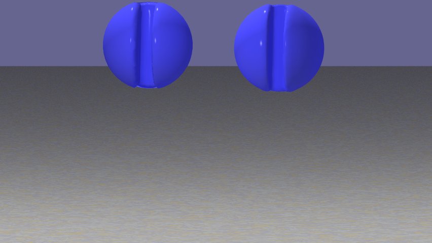
6.2.3. Zalesak’s Sphere
On the domain , a three dimensional slotted sphere of radius , initially centered at , with a slot width of and slot depth of is is rotated under the velocity field
The test is performed on a grid. The time step is . At the inflow edges , homogeneous Neumann boundary conditions are prescribed.
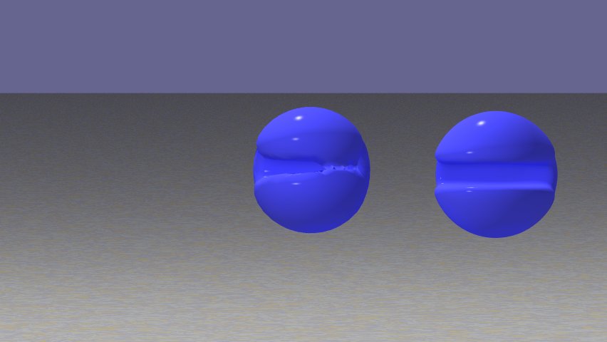
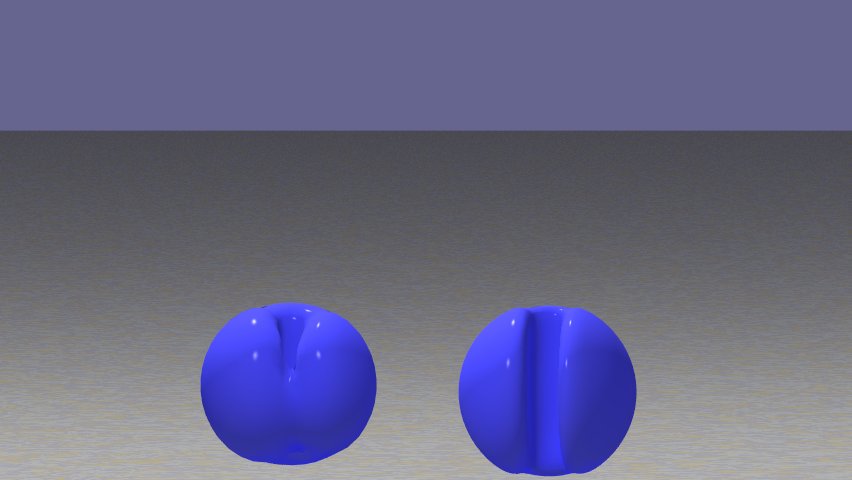
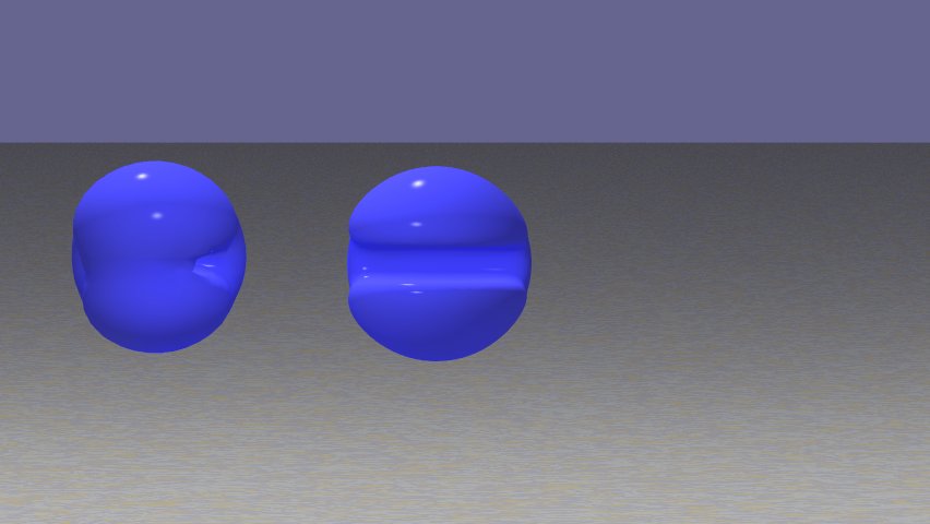
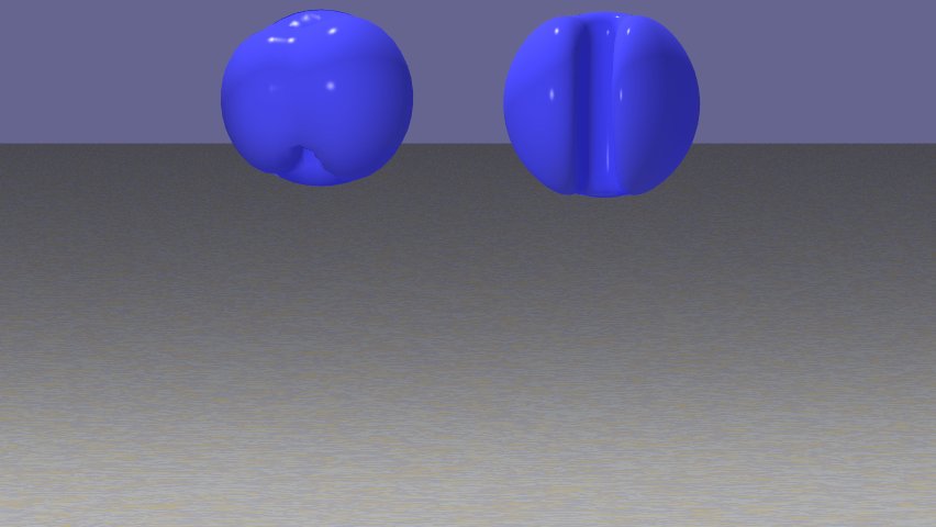
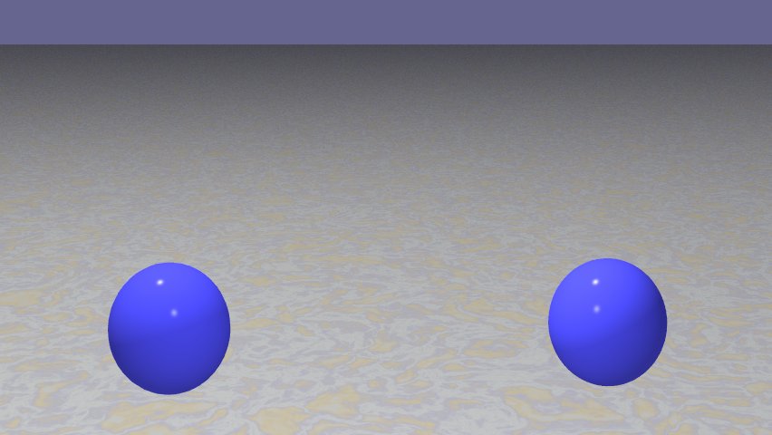
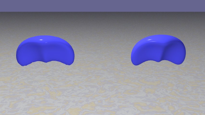
In Fig. 12, the Zalesak’s sphere for a sequence of snapshots during one full revolution is shown, using the gradient-augmented level set method (on the right), and the classical level set approach (on the left). We observe that the gradient-augmented approach preserves the correct shape of the surface better than the classical level set method does. In particular, it is able to maintain the notch on the Zalesak’s sphere, in contrast to the standard approach which merges both sides while significantly gaining mass.
6.2.4. 3D Deformation Field
LeVeque proposed a three dimensional incompressible flow field [9] which combines a deformation in the - plane with one in the - plane. The velocity is given by
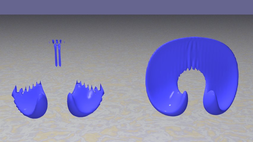
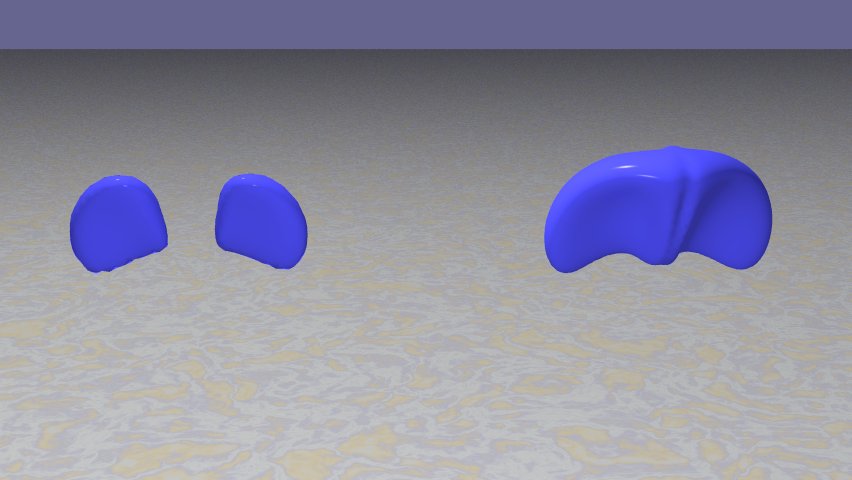
The field is modulated in time using . Here, we consider . The tests is performed on a grid. A sphere of radius that is initially centered at , is advected up to , i.e. it is deformed by the flow, and then brought back to its initial configuration. As before, we compare the gradient-augmented scheme with WENO, both with .
In Fig. 12, a sequence of snapshots is shown, using the gradient-augmented level set method (on the right), and the classical level set approach (on the left). We observe the CIR method’s ability to conserve mass and maintain the topology of the sphere more accurately than the standard approach. In the middle frame, one can observe that the classical level set method suffers a significant loss of mass around the time of maximal deformation , at which the surface is very thin. Evidently, the ability of the gradient-augmented level set method to represent structures of subgrid size is particularly beneficial here.
Note that the jagged edges seen in the middle frame in Fig. 12 are due to the representation of a surface that is thinner than the grid resolution. While these grid effects are present in both numerical schemes, the level set functions themselves do not show any spurious oscillations.
6.2.5. Computational Effort
Both in 2D and 3D, the gradient-augmented level set method carries about the same computational cost as the classical level set method. More specifically, we compare the CPU times for the computation of the 2D deformation field, considered in Sect. 6.2.2, on a grid, using a single core desktop computer. The classical level set approach takes 13 seconds with reinitialization, and 10 seconds without (in which case the quality of the results is significantly reduced). In comparison, the gradient-augmented approach takes 9 seconds when the superconsistent Shu-Osher RK3 method is used, and 8 seconds when gradients are updated using Heun’s method. These ratios carry approximately over to other grid resolutions and other tests.
Gradient-augmented CIR method
 grid
grid
 grid
grid
 grid
grid
 grid
grid
WENO
 grid
grid
 grid
grid
 grid
grid
 grid
grid
WENO with reinitialization
 grid
grid
 grid
grid
 grid
grid
 grid
grid
| resolution | ||||
|---|---|---|---|---|
| GA-CIR | -6.4% | -2.9% | -2.0% | -1.3% |
| WENO | -63.1% | -14.1% | -4.3% | -2.0% |
| WENO reinit | -66.3% | -9.0% | -2.9% | -1.3% |
Gradient-augmented CIR method
 grid
grid
 grid
grid
 grid
grid
 grid
grid
WENO
 grid
grid
 grid
grid
 grid
grid
 grid
grid
WENO with reinitialization
 grid
grid
 grid
grid
 grid
grid
 grid
grid
| resolution | ||||
|---|---|---|---|---|
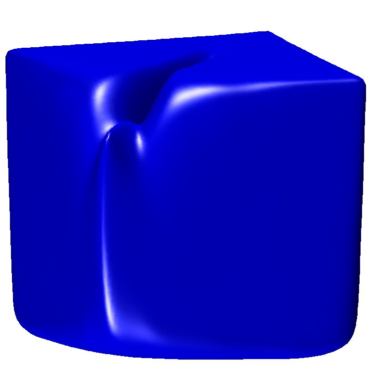
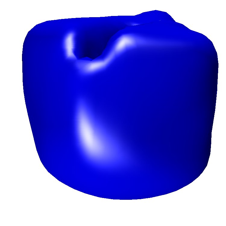
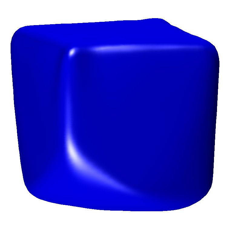
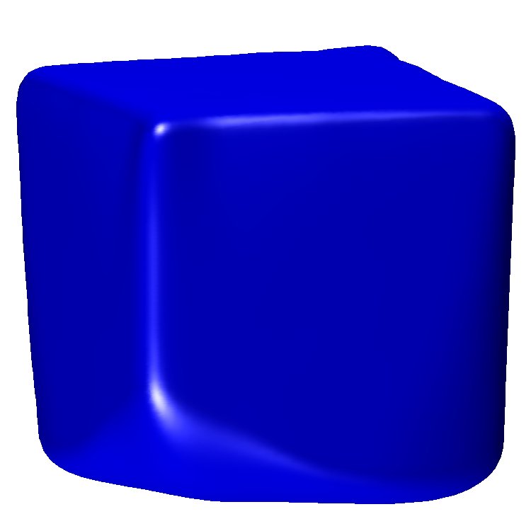
| GA-CIR | -5.4% | -3.3% | -1.6% | -0.9% |
| WENO | -54.5% | -15.8% | -9.6% | -6.5% |
| WENO reinit | -35.4% | -11.2% | -7.1% | -5.0% |
6.2.6. Volume Loss
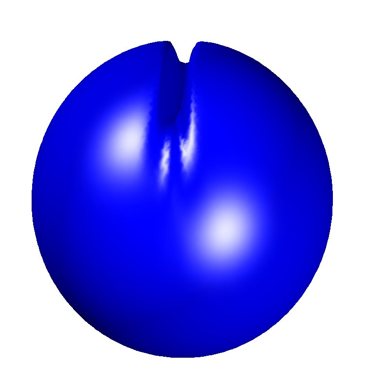
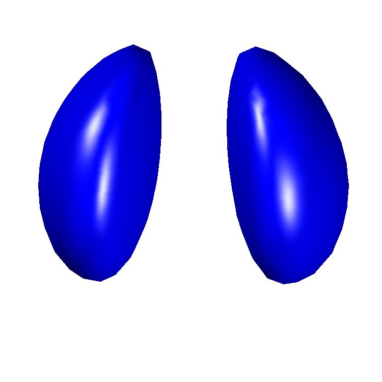
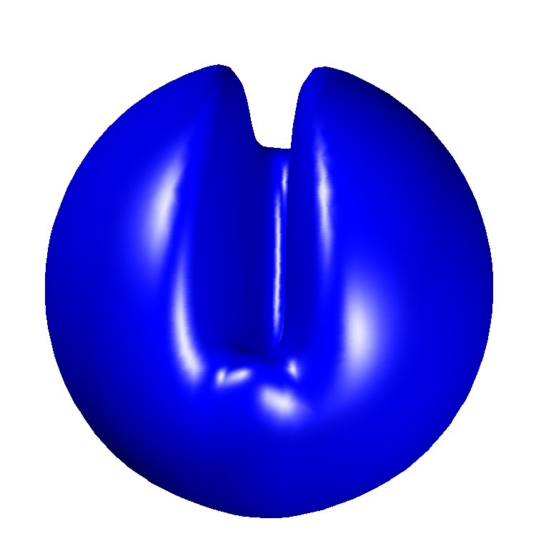
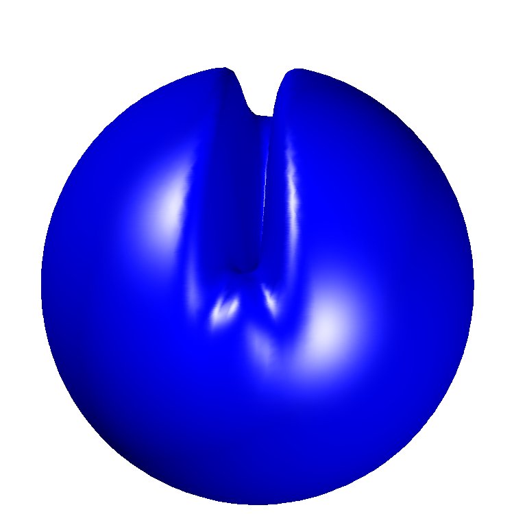
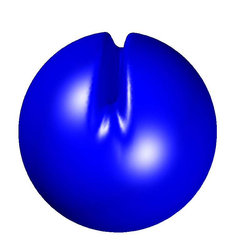
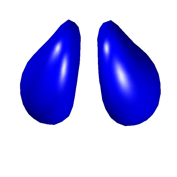
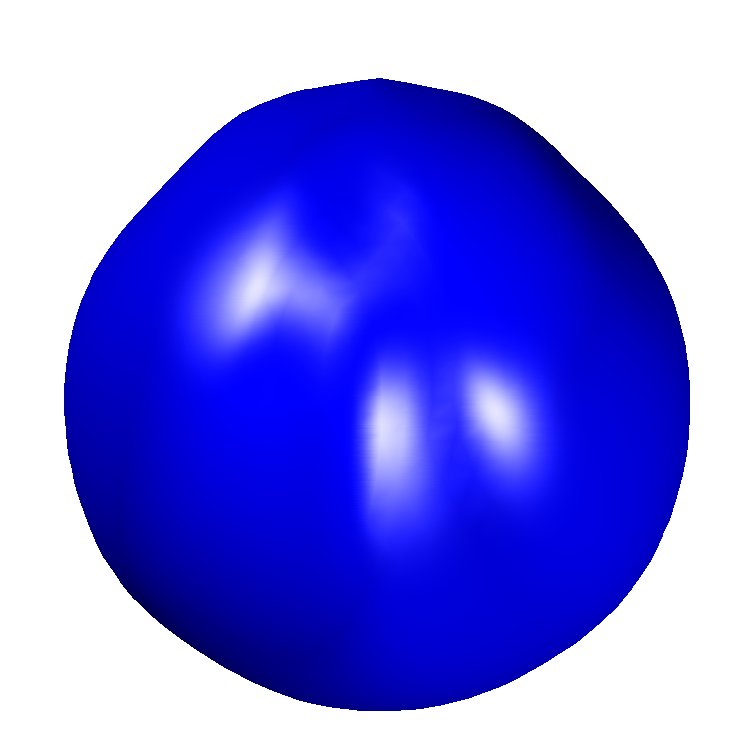
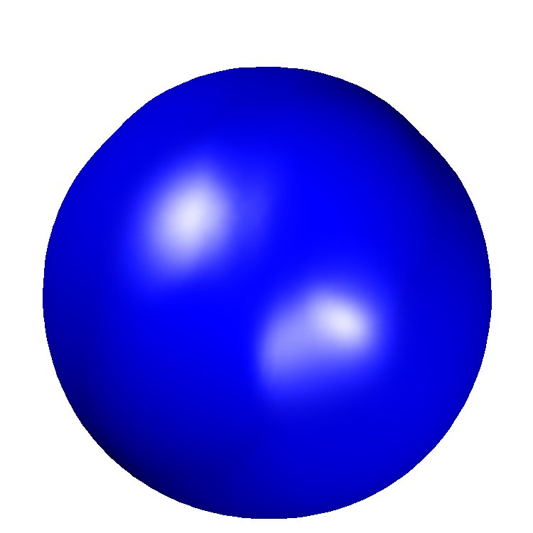
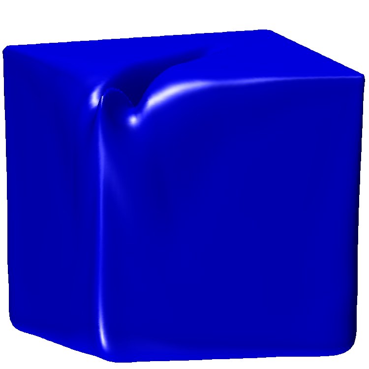
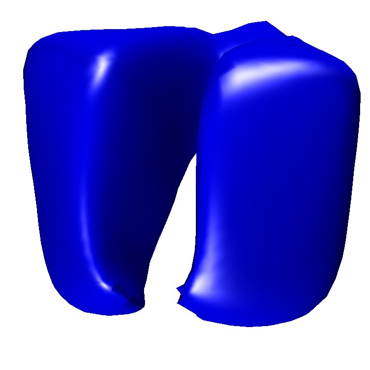
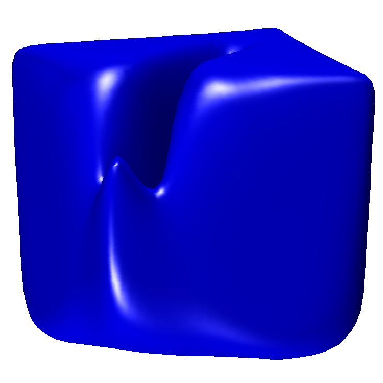
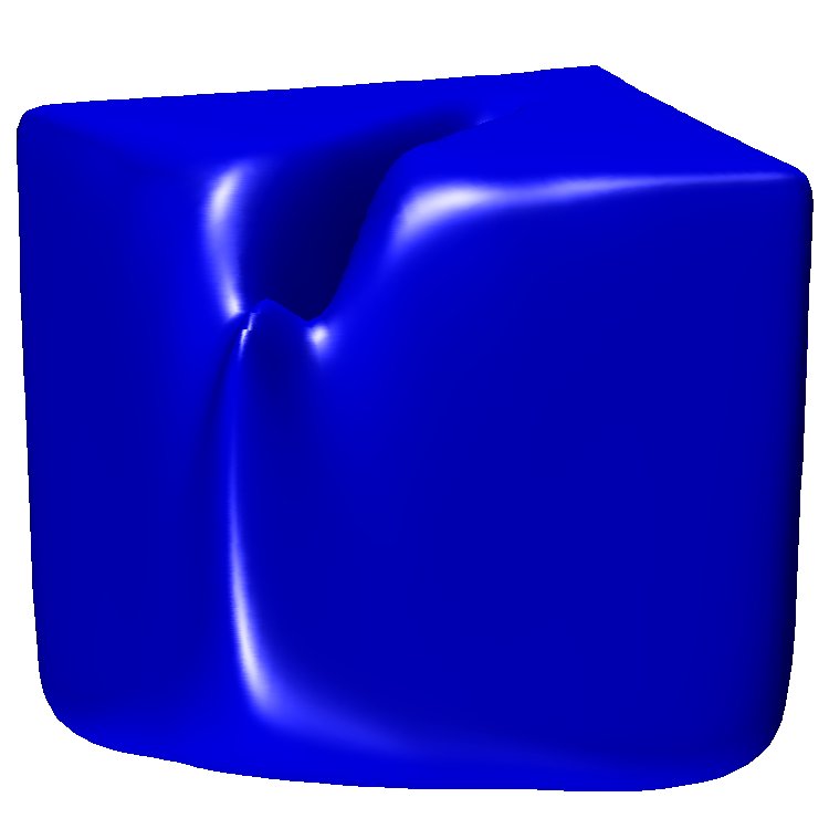
For the 3D deformation field defined in Sect. 6.2.4, we investigate the loss of volume of two closed surfaces (a sphere and a cube), and its dependence on the grid resolution. We compare the gradient-augmented CIR method with the classical WENO scheme, once without, and once with reinitialization. The four considered grid resolutions are , , , and . As the middle picture in Fig. 12 shows, the surface becomes thinner than the grid resolution on a grid.
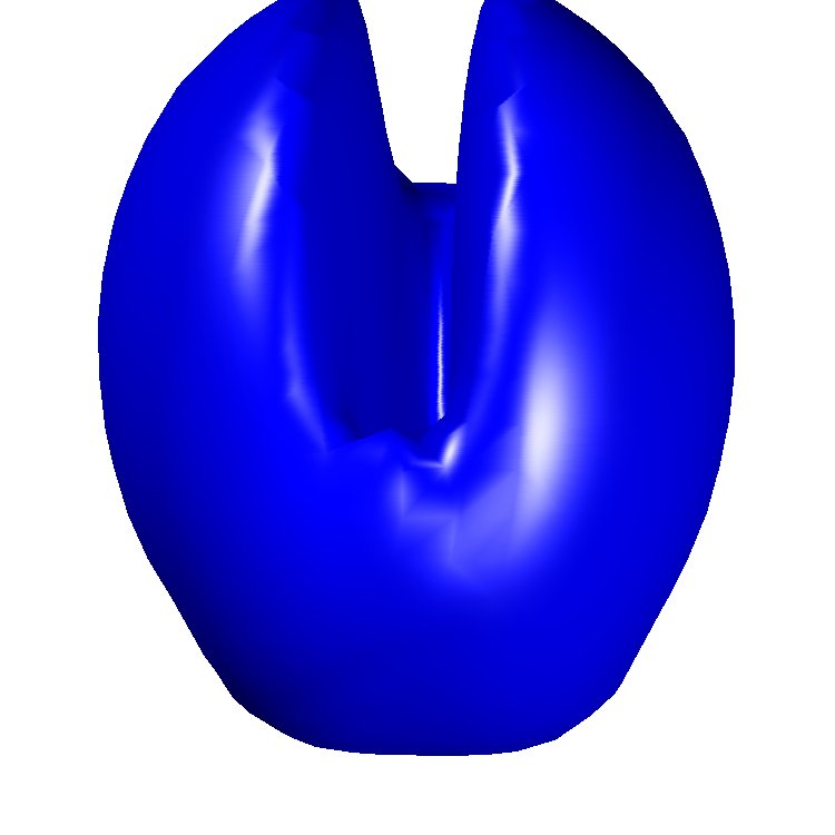
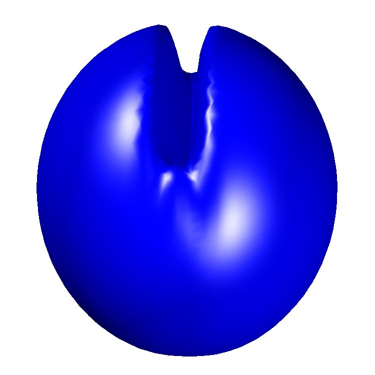
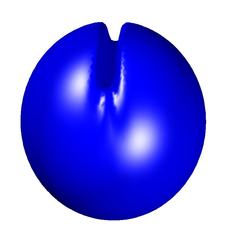
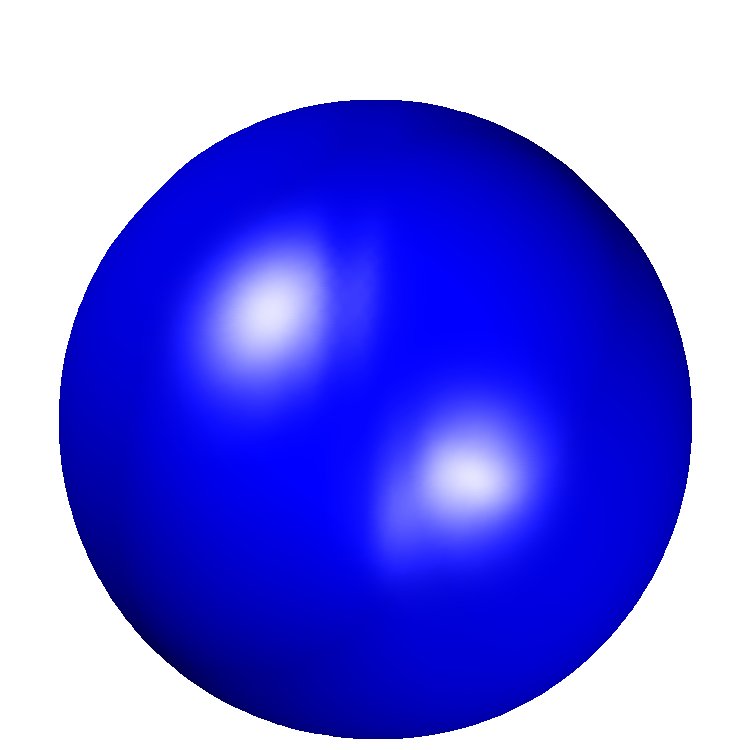
Fig. 13 shows the final state () of a sphere of radius , centered at , under the evolution by the velocity field given in Sect. 6.2.4. In all cases, the final shape has lost some volume. The specific relative volume loss is shown in Table 1. One can observe that the gradient-augmented scheme performs significantly better than the classical schemes if the grid resolution is on the order of the size of the smallest structures. This indicates that gradient-augmented schemes can be expected to particularly improve the resolution of small structures in realistic flow simulations, for which features on various length scales have to be resolved. The results shown in Fig. 13 also clearly show the convergence of all three schemes to a perfect sphere, as the grid resolution is increased.
Another interesting observation can be made about reinitialization. The comparison of WENO without reinitialization and WENO with reinitialization, shown in Fig. 13, indicates that reinitialization generally improves the quality of the obtained results. Small structures are represented in a more robust fashion, and consequently the loss of volume is reduced. In addition, the shape of the final surface appears closer to a true sphere. In particular, reinitialization flattens out the numerical notch that is present in the top two rows in Fig. 13.
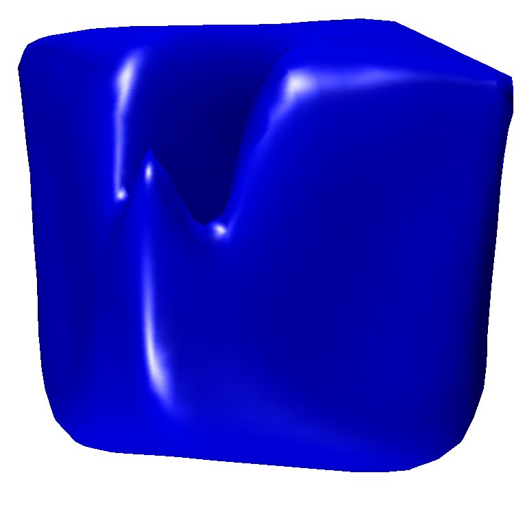
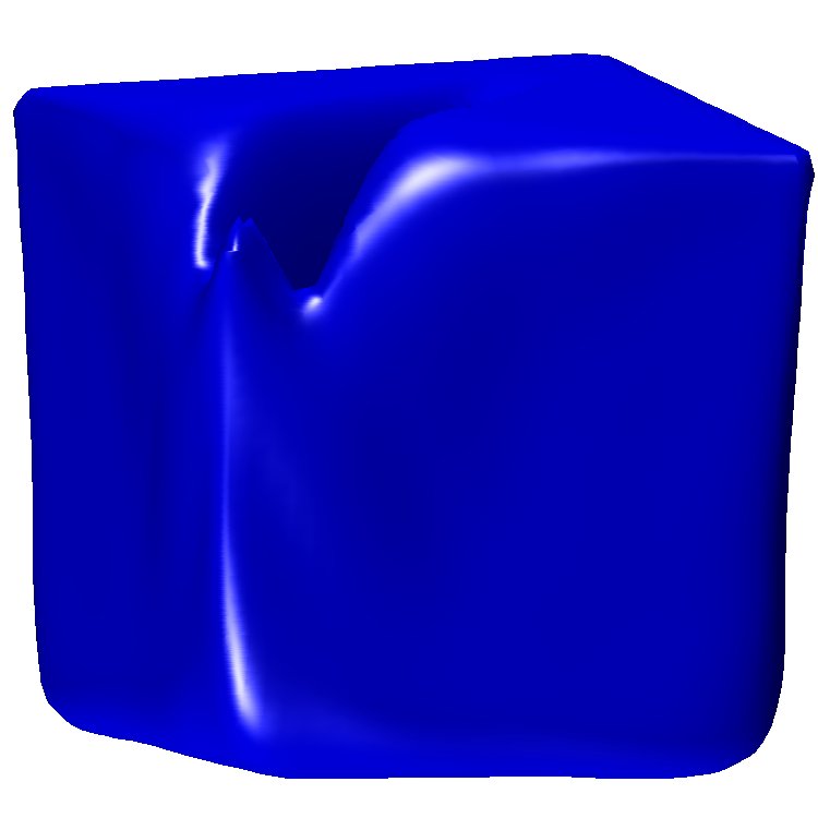
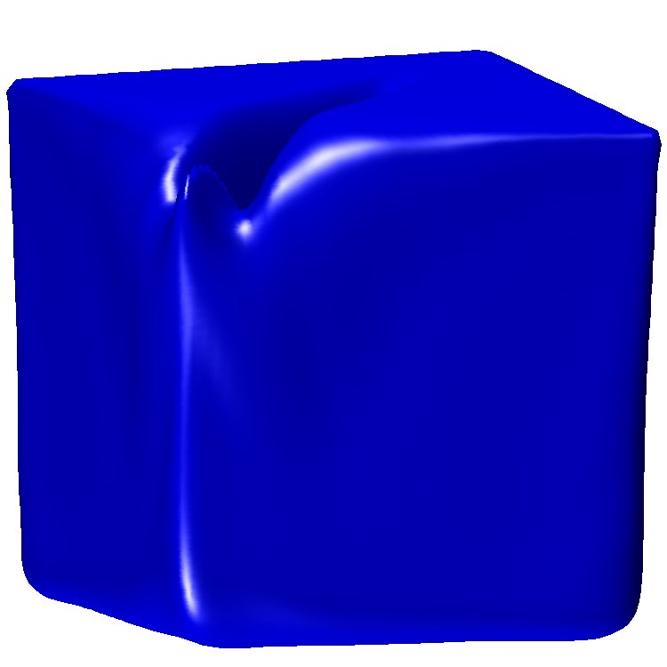
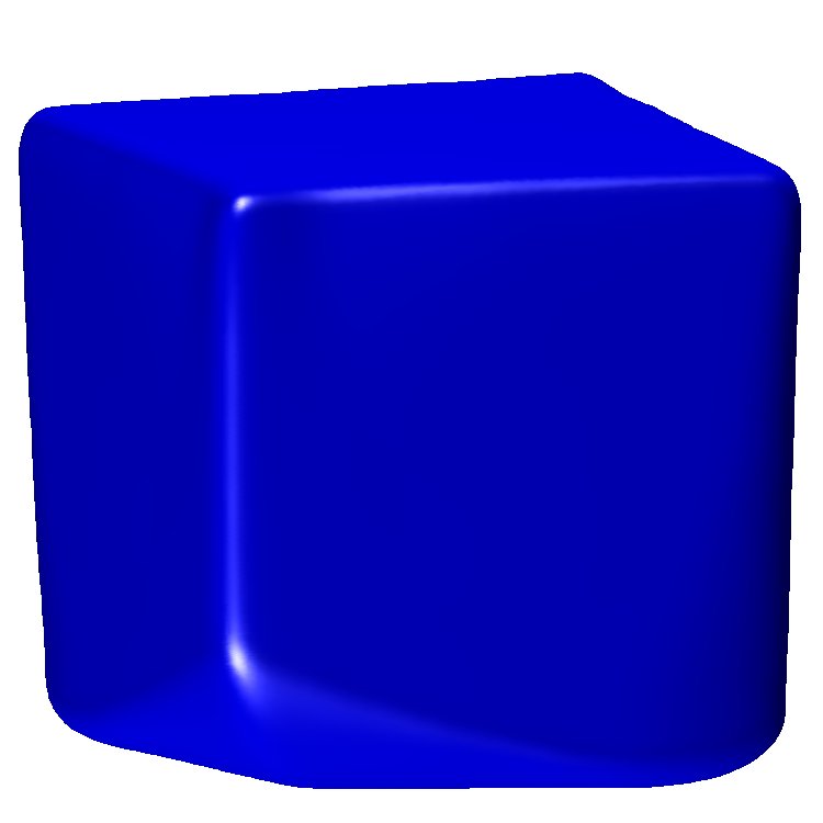
However, reinitialization has a tendency to make surfaces round, and thus it performs particularly well for surfaces that are similar to spheres. This can be clearly seen in the results shown in Fig. 14. For the same 3D deformation field, now a cube of size , centered at , is evolved. Observe that reinitialization smears out the numerical notch (which is good), but also rounds the bottom face of the cube (which is bad). This effect is also visible in the loss of volume, given in Table 2. Observe that for the considered cube, a significant volume loss occurs for WENO, both with and without reinitialization. In contrast, the volume loss with the gradient-augmented scheme is much smaller. In addition, the results in Fig. 14 again show that in relation to classical schemes, the gradient-augmented scheme performs particularly well for low grid resolutions.
7. Conclusions and Outlook
The results presented in this paper show that common problems with level set methods can be ameliorated when incorporating gradients as an independent quantity into the computation. The presented gradient-augmented level set method is based on a Hermite interpolation, which is used as a fundamental ingredient for the reconstruction of the surface, the approximation of surface normals and curvature, and the advection under a given velocity field. In this paper, we consider a -cubic Hermite interpolant, that in each grid cell is defined solely by data on the cell vertices. We have shown that this -cubic interpolant gives rise to a certain level of subgrid resolution, to a second order accurate approximation of curvature, and to a globally third order accurate advection scheme. Curvature is obtained at arbitrary positions by analytically differentiating the -cubic interpolant. The advection scheme is based on a generalization of the CIR method. Characteristic curves are traced backwards from grid points, and function values and derivatives of the level set function are obtained from the -cubic interpolant, respectively its derivatives. Therefore, the resulting approximations and schemes are optimally local, i.e. information at a given (grid) point is updated by using data from only a single cell. This promises a simpler treatment of adaptive mesh refinement and boundary conditions.
In the theoretical investigation of gradient-augmented schemes, the concept of superconsistency has been introduced, which admits the interpretation of a gradient-augmented method as an evolution rule in a function space, in which analytical coherence between function values and gradients is preserved. In each time step a projection rule is applied, that is based on an interpolation. In this paper, the specific case of a -cubic Hermite interpolation is studied. Employing the introduced concepts, the accuracy and stability of the generalized CIR method have been investigated theoretically and verified in numerical experiments. In addition, the performance of the gradient-augmented level set approach has been compared to a classical high-order level set method, both in 2D and 3D benchmark tests. While of similar computational cost, the gradient-augmented approach generally yields more accurate results. In particular, small structures are preserved much better than with the classical level set method. The ability to represent structures of subgrid size turns out to be of great benefit.
While the presented approach looks promising and performs well in numerical tests, various aspects remain to be investigated. The proof of stability presented in this paper covers only a special case, and a general proof of stability is one key objective of our current research. Another question of theoretical importance is the issue of reinitialization. All numerical tests with the generalized level set method considered in this paper have been done without reinitialization. While the knowledge of gradients itself generally gives rise to a more accurate recovery of the surface, an additional reinitialization may improve the quality of the method even further.
A fundamental question of interest in the technical realm is the combination of the gradient-augmented level set approach with adaptive mesh refinement. Here, the optimal locality of the advection scheme may prove advantageous, and preserve automatically the high-order accuracy through various levels of grid refinement. Also, the combination with Lagrangian particles, such as done in [6] for the classical level set method, is of interest. Another important aspect to be investigated is the case of the velocity field, and its gradient, not being accessible everywhere. Most prominently, this is the case in multi-phase fluid flow simulations, in which the evolution of the level set function is coupled to an evolution for the fluid velocities. In future research, we plan to investigate the incorporation of the presented gradient-augmented level set method into a ghost fluid method [7]. One of various challenges with this approach is the new possibility of up to three intersections of the reconstructed surface with each cell edge.
The -cubic interpolant considered in this paper yields an accurate method, but as discussed in Sect. 3.1, it may be too smooth to capture small structures when these are represented by a signed distance function. Hence, it is an important question to investigate whether other types of interpolation can improve the ability to capture subgrid structures. A related question is whether it is beneficial to additionally augment the method by higher derivatives. For instance, having direct access to the Hessian of the level set function may give rise to an even better representation of small structures, and an even more accurate approximation of curvature. Another question is whether the gradient-augmented approach can be generalized to, and yields good methods for, other types of evolution equations. Simple generalization of the linear advection equation are the level set reinitialization equation, or the G-equation in combustion modeling [13]. More complex examples are problems involving diffusion, up to the actual equations of fluid flow. A consistently coupled gradient-augmented scheme for both the two-phase Navier-Stokes equations and the level set equation for the interface could not only allow the representation of subgrid structures, but also yield a certain level of subgrid resolution in the actual fluid flow simulation.
Acknowledgments
The authors would like to acknowledge the support by the National Science Foundation. This research was supported by grant DMS–0813648. Rodolfo Ruben Rosales would like to acknowledge partial support by the Universidad Carlos III de Madrid, Spain.
References
- [1] D. Adalsteinsson and J. A. Sethian. The fast construction of extension velocities in level set methods. J. Comput. Phys., 148:2–22, 1999.
- [2] J. Bell, P. Colella, and H. Glaz. A second-order projection method for the incompressible Navier-Stokes equations. J. Comput. Phys., 85:257–283, 1989.
- [3] D. L. Chopp. Some improvements of the fast marching method. SIAM J. Sci. Comput., 23(1):230–244, 2001.
- [4] P. Colella and P. R. Woodward. The piecewise parabolic method (PPM) for gas-dynamical simulations. J. Comput. Phys., 54:174–201, 1984.
- [5] R. Courant, E. Isaacson, and M. Rees. On the solution of nonlinear hyperbolic differential equations by finite differences. Comm. Pure Appl. Math., 5:243–255, 1952.
- [6] D. Enright, R. Fedkiw, J. Ferziger, and I. Mitchell. A hybrid particle level set method for improved interface capturing. J. Comput. Phys., 183:83–116, 2002.
- [7] R. Fedkiw and X.-D. Liu. The ghost fluid method for viscous flows. In M. Hafez and J. Chattot, editors, Innovative Methods for Numerical Solutions of Partial Differential Equations, pages 111–143, New Jersey, 2002. World Scientific Publishing.
- [8] P.D. Lax and R.D. Richtmyer. Survey of the stability of linear finite difference equations. Commun. Pure Appl. Math., 9:267–293, 1956.
- [9] R. LeVeque. High-resolution conservative algorithms for advection in incompressible flow. SIAM J. Numer. Anal., 33:627–665, 1996.
- [10] X.-D. Liu, S. Osher, and T. Chan. Weighted essentially non-oscillatory schemes. J. Comput. Phys., 115:200–212, 1994.
- [11] W. E. Lorensen and H. E. Cline. Marching cubes: A high resolution 3D surface construction algorithm. Computer Graphics, 21(4):163–169, 1987.
- [12] C.-H. Min and F. Gibou. A second order accurate level set method on non-graded adaptive cartesian grids. J. Comput. Phys., 225(1):300–321, 2007.
- [13] M. Oberlack, H. Wenzel, and N. Peters. On symmetries and averaging of the G-equation for premixed combustion. Combust. Theory Model., 5:363–383, 2001.
- [14] S. Osher and J. A. Sethian. Fronts propagating with curvature–dependent speed: Algorithms based on Hamilton–Jacobi formulations. J. Comput. Phys., 79:12–49, 1988.
- [15] M. Raessi, J. Mostaghimi, and M. Bussmann. Advecting normal vectors: A new method for calculating interface normals and curvatures when modeling two-phase flows. J. Comput. Phys., 226(1):774–797, 2007.
- [16] J. A. Sethian. A fast marching level set method for monotonically advancing fronts. Proc. Nat. Acad. Sci., 93(4):1591–1595, 1996.
- [17] C.-W. Shu and S. Osher. Efficient implementation of essentially non-oscillatory shock-capturing schemes. J. Comput. Phys., 77:439–471, 1988.
- [18] J. Strain. Tree methods for moving interfaces. J. Comput. Phys., 151(2):616–648, 1999.
- [19] M. Sussman and E. Fatemi. An efficient, interface preserving level set redistancing algorithm and its application to interfacial incompressible fluid flow. SIAM J. Sci. Comput., 20(4):1165–1191, 1999.
- [20] M. Sussman, P. Smereka, and S. Osher. A level set approach for computing solutions to incompressible two-phase flow. J. Comput. Phys., 114(1):146–159, 1994.
- [21] H. Takewaki, A. Nishiguchi, and T. Yabe. Cubic interpolated pseudoparticle method (CIP) for solving hyperbolic type equations. J. Comput. Phys., 61:261–268, 1985.
- [22] H. Takewaki and T. Yabe. Cubic-interpolated pseudo particle (CIP) method – Application to nonlinear or multi-dimensional problems. J. Comput. Phys., 70:355–372, 1987.
- [23] B. van Leer. Towards the ultimate conservative difference scheme I. The quest of monoticity. Springer Lecture Notes in Physics, 18:163–168, 1973.
- [24] B. van Leer. Towards the ultimate conservative difference scheme II. Monotonicity and conservation combined in a second order scheme. J. Comput. Phys., 14:361–370, 1974.
- [25] B. van Leer. Towards the ultimate conservative difference scheme III. Upstream-centered finite-difference schemes for ideal compressible flow. J. Comput. Phys., 23:263–275, 1977.
- [26] B. van Leer. Towards the ultimate conservative difference scheme IV. A new approach to numerical convection. J. Comput. Phys., 23:276–299, 1977.
- [27] B. van Leer. Towards the ultimate conservative difference scheme V. A second-order sequel to Godunov’s method. J. Comput. Phys., 32:101–136, 1979.
- [28] S. Zalesak. Fully multidimensional flux-corrected transport algorithms for fluids. J. Comput. Phys., 31:335–362, 1979.