Analysis of Strain Fields in Silicon Nanocrystals
Abstract
Strain has a crucial effect on the optical and electronic properties of nanostructures. We calculate the atomistic strain distribution in silicon nanocrystals up to a diameter of 3.2 nm embedded in an amorphous silicon dioxide matrix. A seemingly conflicting picture arises when the strain field is expressed in terms of bond lengths versus volumetric strain. The strain profile in either case shows uniform behavior in the core, however it becomes nonuniform within 2-3 Å distance to the nanocrystal surface: tensile for bond lengths whereas compressive for volumetric strain. We reconsile their coexistence by an atomistic strain analysis.
pacs:
61.46.Hk, 68.35.CtThe low dimensional forms of silicon embedded in silica have strong potential as an optical material.nanosi Such heterogeneous structures inherently introduce the strain as a degree of freedom for optimizing their opto-electronic properties. It was realized earlier that strain can be utilized to improve the carrier mobility in bulk silicon based structures.manasevit This trend has been rapidly transcribed to lower dimesional structures, starting with two-dimensional silicon structures.people Recently for silicon nanowires, there have been a number of attempts to tailor their optical properties through manipulating strain.lyons ; hong Futhermore, recent studies have revealed that the strain can become the major factor restricting the crystallization of the nanolayers.zachariasPRB ; hernandez It depends on several factors, most important of which are the lattice mismatch between the constituents, size of the NCs, and the growth conditions, such as the details of the growth procedure.zach99 In summary, for improving the optical and electronic properties of nanocrystals (NCs), the strain engineering has become an effective tool to be exploited.thean ; peng ; smith A critical challenge in this regard is to analyze the strain state of the Si NCs embedded in silica.
The close relations between strain and optical or electronic properties in Si NCs have very recently become the center of attention.peng ; hadji07 ; ossicini There still remains much to be done in order to understand strain in nanostructures at the atomistic level. As pioneered by Tsu et al. Raman spectroscopy can be an effective experimental tool for determining the strain state of the Si NCs.tsu Specifically, recent Raman studies reported that the Si NCs may be under a thermal residual strain and this can be reduced by overall annealing at high temperatureszach99 or by local laser annealing.arguirov Due to small density difference between Si NC and the surrounding a-SiO2, a limited information can be gathered about its structure using transmission electron microscopy (TEM) or even high resolution TEM techniques.coffin Especially, molecular dynamics simulations with realistic interaction potentials present an opportunity, by providing more detailed critical information then the best imaging techniques currently available and clarify the analysis of experimental results. Along this direction, previously dundar we focused on Si-Si bond length distribution and reported that Si-Si bond lengths are stretched upto 3 just below the surface of Si NCs embedded in amorphous SiO2 which has also been very recently confirmed.ippolito
In this Letter, we analyze the volumetric and bond length strain distributions in Si NCs, in particular demonstrate that both compressive volumetric strain and tensile bond length strain coexist within the same Si NC. We accomplish this by performing trajectory analysis on model samples (with ca. 5000 atoms) simulated via molecular dynamics using a reliable and accurate as well as reactive force field.adri The simulation details are similar to our previous work,dundar except the way we construct the Si NC in glass matrix. Instead of deleting all glass atoms within a predetermined radius, we remove the glass atoms after rigorously defining the surface of the nanocrystal through the Delaunay triangulation method.geompack In this way, we have constructed NCs embedded in glass matrix with diameters ranging from 2.2 nm to 3.2 nm without introducing built-in strain to the system. In this diameter range we observe similar trends in strain, volumetric strain, and bond length distribution etc., therefore, we present only the figures of the system for a typical NC of radius 2.6 nm.
In the language of geometry, strain is defined through an affine transformation that maps the undeformed state to deformed state, which is called deformation gradient. Several methods to derive discrete form of deformation gradient from atomic positions are reported.gullett ; pryor ; curtin In the method proposed by Pryor et al., the atomistic strain tensor is derived from local transformation matrix that transforms nearest neighbors of a certain atom from its undeformed state to the deformed one. From the MD simulations, using positions of NC atoms, we first extract each atom’s displacement vector from its undeformed site which is determined by positioning an ideal tetrahedron to the local environment. Using these displacement vectors, we construct deformation matrix and derive the atomistic strain tensor from this local deformation tensor.pryor The first invariant of strain tensor corresponds to the hydrostatic strain.elasticity As an alternative measure to hydrostatic strain, we calculate volumetric strain by considering volume change of a tetrahedron from its undeformed counterpart. A third measure as we have used in our previous report,dundar is the bond length strains.
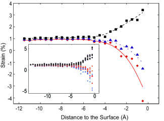
To verify our results we have calculated strain distribution in NC region for all mentioned measures. We have plotted all three of them in Fig. 1. The results of volumetric strain are very close to hydrostatic strain which is the trace of strain tensor calculated with aferomentioned technique.pryor In these results, we observe a net compressive behavior of strain just under the surface and a uniform tensile strain of about 1 at the core of NC. Si-Si bonds are stretched by about 1 in the core region in agreement with the hydrostatic and volumetric strains, however, just under the surface, Si-Si bonds are stretched up to 3 where hydrostatic and volumetric strain results indicate compressive strain state. The bond-stretch in Si-Si bonds due to oxidation has been shown earlier by us using molecular dynamics simulationsdundar which was also confirmed by other approaches.ippolito
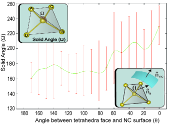
Occurrence of compressive volumetric strain and stretched bond lengths in the same outer region may initially seem contradicting. However, stretching of bonds does not imply that the system is under tensile hydrostatic strain as well. Consider a tetrahedron formed by a Si atom and its four Si neighbors (A, B, C, D) as shown in upper inset of Fig. 2. In the ideal case, the solid angle () subtended by each triangular face of this tetrahedron should be equal to . Under a uniform deformation, bond lengths will also be stretched, while the solid angles remain unchanged. However, under a nonuniform deformation, the change in three solid angles causes a decrease in the volume of the tetrahedron while increasing or preserving the bond lengths. Hence, a combination of stretched bond lengths with deformed solid angles may end up with an overall reduction of the volume of the tetrahedron. This explains the coexistance of compressive volumetric strain and stretched bond lengths at the region just below the surface of NCs.
To better visualize the nature of the deformation of the Si NCs, we consider the orientational variation of the solid angles of the tetrahedral planes. As illustrated in the lower inset of Fig. 2, the two important directions are the unit normal () of the tetrahedron face subtending the solid angle under consideration, and the local outward surface normal () of the NC. It is clearly seen from Fig. 2 that solid angles subtended by tetrahedra faces oriented outward to the NC surface are increased up to , whereas those facing inward to the NC core are decreased down to . This dependence is a clear evidence of how oxidation affects strain distribution close to the interface.
To further quantify the atomistic strain in the highly critical region within 3 Å distance to the interface, we classify the average bond length and hydrostatic strain behaviors into three categories. Figure 3 displays the percentage as well as the bonding details of each category.
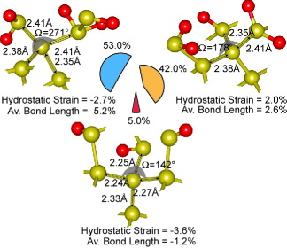
In top-left, we illustrate most common type with a share of 53.0 which is responsible for the opposite behavior in Fig. 1 where average bond lengths of center Si atoms to its four nearest neighbors are stretched but net atomistic strain at this atom is compressive. In this case solid angles facing toward the oxide region is increased to due to oxygen bonds of Si neighbors. Although these oxygen bonds stretched Si-Si bonds to Å, net strain on center Si atom is -2.7. In the top-right part of the Fig. 3 we illustrate second most often case with a percentage of 42.0, where average bond lengths and atomistic strain show similar behavior; bond lengths are stretched and net hydrostatic strain is tensile. In this case oxidation somewhat uniformly deforms the bonds so that solid angles are still around which is the value for the unstrained case. Finally, as shown at bottom of Fig. 3, a very small percentage of atoms (5.0) in the region beneath the surface have shortened bond lengths and compressive atomistic strain.
In summary, we study the strain state of Si NCs in silica matrix with diameters in 2 to 3.2 nm. The structure is assumed to be free from any thermal built-in strains. The core region of the NC is observed to be under a uniform 1% tensile strain, where both bond length and volumetric strain measures are in agreement. However, towards the NC interface, while the Si-Si bonds become more stretched, the hydrostatic strain changes in the compressive direction. In the interpretation of the indirect strain measurements eg. from spectroscopy, this dual character needs to be taken into consideration. We explain these two behaviors using the solid angle deformation of the tetrahedral-bonded Si atoms, and demonstrate that it is ultimately caused by the oxygen atoms at the interface. An equally important finding is that the overall strain profile within the Si NCs is quite nonuniform. As very recently emphasized, within the context of centrosymmetric materials, like silicon, such strain gradients locally break the inversion symmetry and may lead to profound physical consequences.majdoub
This work has been supported by the Turkish Scientific and Technical Council TÜBİTAK with the Project No. 106T048 and by the European FP6 Project SEMINANO with the Contract No. NMP4 CT2004 505285. The visit of Tahir Çağın to Bilkent University was facilitated by the TÜBİTAK BİDEB-2221 program. TC also acknowledges the support of NSF-IGERT.
References
- (1) V. Kumar (Editor), Nano Silicon, (Elsevier, London, 2007).
- (2) H. M. Manasevit, I. S. Gergis, and A. B. Jones, Appl. Phys. Lett. 41, 464 (1982).
- (3) R. People, J. C. Bean, D. V. Lang, A. M. Sergent, H. L. Stormer, K. W. Wecht, R. T. Lynch, and K. Baldwin, Appl. Phys. Lett. 45, 1231 (1984).
- (4) D. M. Lyons, K. M. Ryan, M. A. Morris, and J. D. Holmes, Nano Lett. 2, 811 (2002).
- (5) K.-H. Hong, J. Kim, S.-H. Lee, and J. K. Shin, Nano Lett. 8, 1335 (2008).
- (6) M. Zacharias and P. Streitenberger, Phys. Rev. B. 62, 8391 (2000).
- (7) S. Hernandez, A. Martinez, P. Parinello, Y. Lebour, B. Garrido, E. Jordana, and J. M. Fedeli, J. Appl. Phys. 104 044304 (2008).
- (8) M. Zacharias, J. Bläsing, P. Veit, L. Tsybeskov, K. Hirschman, and. P. M. Fauchet, Appl. Phys. Lett. 74, 2614 (1999).
- (9) A. Thean and J. P. Leburton, Appl. Phys. Lett. 79, 1030 (2001).
- (10) X. H. Peng, S. Ganti, A. Alizadeh, P. Sharma, S. K. Kumar, and S. K. Nayak, Phys. Rev. B 74, 035339 (2006).
- (11) A. M. Smith, A. M. Mohs, and S. Nie, Nature Nanotechnol. 4 56 (2009).
- (12) G. Hadjisavvas and P.C. Kelires, Physica E 38, 99 (2007).
- (13) R. Guerra, I. Marri, R. Magri, L. Martin-Samos, O. Pulci, E. Degoli, and S. Ossicini, Superlattices and Microstructures (2008), doi:10.1016/j.spmi.2008.10.020.
- (14) R. Tsu, H. Shen, and M. Dutta, Appl. Phys. Lett. 60, 112 (1992).
- (15) T. Arguirov, T. Mchedlidze, M. Kittler, R. Rolver, B. Berghoff, M. Frost and B. Spangenberg, Appl. Phys. Lett. 89, 053111 (2006).
- (16) H. Coffin, C. Bonafos, S. Schamm, N. Cherkashin, G. B. Assayag, A. Claverie, M. Respaud, P. Dimitrakis and P. Normand, J. Appl. Phys. 99, 044302 (2006)
- (17) D. E. Yılmaz, C. Bulutay, and T. Çağın, Phys. Rev. B. 77, 155306 (2008).
- (18) M. Ippolito, S. Meloni, and L. Colombo, Appl. Phys. Lett. 93, 153109 (2008).
- (19) A. C. T. van Duin, A. Strachan, S. Stewman, Q. Zhang, X. Xu, and W. A. Goddard,III, J. Phys. Chem. A 107, 3803 (2003).
- (20) B. Joe, Adv. in Eng. Soft., 13, 325 (1991).
- (21) P. M. Gullett, M. F. Horstemeyer, M. I. Baskes, and H. Fang, Modelling Simul. Mater. Sci. Eng. 16, 015001 (2008).
- (22) W. A. Curtin and R. E. Miller, Modelling Simul. Mater. Sci. Eng. 11, R33 (2003).
- (23) C. Pryor, J. Kim, L. W. Wang, A. J. Williamson and A. Zunger, J. Appl. Phys. 83, 2548 (1998).
- (24) P. C. Chou and N. J. Pagano, Elasticity-Tensor, Dyadic and Engineering Approaches, (Dover, Princeton, 1967).
- (25) M. S. Majdoub, P. Sharma, and T. Cagin, Phys. Rev. B. 77, 125424 (2007).