Electron Self-injection in Multidimensional Relativistic Plasma Wakefields
Abstract
We present an analytical model for electron self-injection in nonlinear, multidimensional plasma wave excited by short laser pulse in the bubble regime or by short electron beam in the blowout regime. In this regimes, which are typical for electron acceleration in the last experiments, the laser radiation pressure or the electron beam charge pushes out background plasma electrons forming a plasma cavity - bubble - with a huge ion charge. The plasma electrons can be trapped in the bubble and accelerated by the plasma wakefields up to very high energies. The model predicts the condition for electron trapping and the trapping cross section in terms of the bubble radius and the bubble velocity. The obtained results are in a good agreement with results of 3D PIC simulations.
pacs:
52.38.Kd,52.65.Rr,52.27.NyPlasma-based charged particle acceleration is now a fast developing area of science. It has attracted much attention due to the recent experimental breakthrough in generation of quasimonoenergetic, dense and short bunches of relativistic electrons with up to GeV energies in the laser-driven acceleration Mangles2004 ; Geddes2004 ; Faure2004 ; Leemans2006 and due to the energy doubling of a GeV electron beam Blumenfeld2007 . The high-gradient acceleration is provided by very strong electromagnetic fields in a plasma wake excited by short laser pulse or electron beam. The plasma electrons are radially expelled by ponderomotive force of the laser pulse or by Lorentz force from the space charge of the electron beam that leads to formation of the plasma cavity - bubble with unshielded ions inside. This is the bubble Pukhov2002 or blowout Rosenzweig1991 regime of laser-plasma and beam-plasma interaction. It is important that a small part of the background plasma electrons can be trapped in the bubble providing the electron self-injection. The bubble velocity is close to the speed of light and the trapped relativistic electrons can be continuously accelerated in the plasma fields up to a very high energy.
The electron self-injection is the key phenomenon of the last laser-plasma acceleration experiments Mangles2004 ; Geddes2004 ; Faure2004 ; Leemans2006 . It is a crucial factor for the quality of the accelerated electron beam. Many applications ranging from x-ray free electron lasers to electron-positron colliders require high quality electron beams with a very low emittance and energy spread. The one-dimensional model based on the Hamiltonian formalism has been developed to study electron trapping in relativistic plasma wave Esarey1995 ; Schroeder2006 . Several optical and plasma techniques have been proposed to enhance the electron self-injection in plasma wakefield like the collision of two counter-propagating laser pulses Esarey1997 ; Faure2006 , density transitions Bulanov1998 ; Suk2001 ; Esirkepov2006 etc. In the ultrahigh intensity regime the radial force from the driver and from the plasma fields strongly affect electron motion and the electron dynamics become complex and multidimensional. The trajectory of the trapped electrons starts at the bubble front, bends around the cavity and becomes caught at the trailing edge of the bubble. Evidently, such trajectories cannot be described in the framework of a one-dimensional model.
Despite the great interest in plasma-based electron acceleration there is little theory of self-injection. In Ref. Lu20062 ; Lu2006 ; Tzoufras2008 a multidimensional model of a relativistic plasma wake including beam loading is proposed, however the electron self-injection was not considered. The electron self-injection has been mainly studied numerically Zhidkov2004 ; Kostyukov2004 ; Lu2007 . It was found in Ref. Lu2007 that a sufficiently large bubble, , can trap plasma electrons. Here is the bubble radius normalized to , is the (non-relativistic) plasma frequency for the background electron density , and , are the charge and mass of the electron, respectively. A different condition for electron self-injection has been proposed in Ref. Kostyukov2004 : , where is the bubble gamma-factor. Unfortunately, principal limitations of a numerical approach make the accuracy and the validity range of the obtained conditions unclear and do not provide an insight in the self-injection physics. However, the numerical approach has its natural limitations in accuracy and validity conditions of the obtained results and does not provide insight in the self-injection physics.
In this paper, we present an analytical model for self-injection and check it by direct measurements of model parameters in 3D particle-in-cell (PIC) simulations. For simplicity we assume that the bubble has a spherical shape with large radius that is typical for relativistic laser pulses. The numerical simulations Kostyukov2004 and theoretical analysis Lu2006 demonstrate that the bubble shape is close to the spherical one for relativistically intense laser pulse and when the number of the trapped electrons is not too large. It can be shown Kostyukov2004 ; Lu2006 that the space-time distribution of the electromagnetic field inside the spherical bubble expressed in cylindrical coordinates is , , where , and is the bubble velocity. We use dimensionless units, normalizing the time to , the lengths to , the velocity to , the electromagnetic fields to , and the electron density, , to . The distribution of the electromagnetic field inside the plasma cavity can be also expressed through vector and scalar potential Kostyukov2004 , with gauge , where is the distance to the bubble center.
We assume that the electron trajectory is plane () because of the axial symmetry of the wakefield and the driver. The driver field is neglected because it is weak at the region where trapping occurs (far behind the laser pulse or electron beam). The field of the trapped particles is also neglected since we assume that the number of the trapped particle is not too large. The electron dynamics in the bubble is governed by the Hamiltonian Kostyukov2004 , where is the canonical momentum of the electron and , are coordinates canonically conjugated to . As the Hamiltonian is not the function of time then it is integral of motion . The Hamiltonian equations are:
| (1) | |||||
| (2) |
where is the relativistic factor of the electron, is the electron momentum.
We assume that the electron is located initially at the bubble border , and at . It follows from the initial condition that
| (3) |
where . We solve the electron motion equations numerically. To be more realistic and in accordance with PIC simulations we include an electron sheath around the plasma cavity, which screens the bubble ion field in the surrounding plasma. We model the electromagnetic fields inside the bubble as follows , , where , is the width of the electron sheath. The similar distribution of the wake field with is observed in the 3D PIC simulation Kostyukov2004 ; Lu2007 . The typical trajectory of a trapped electron is shown in Fig. 1 for , and . The sheath does not affect the electron trajectory in the bubble when . We can conclude from the numerical solutions that the electron very soon becomes ultrarelativistic so that . The electron undergoes betatron oscillations about the -axis and slowly moves along this axis (). The condition can be considered as a necessary (but not sufficient) one for electron trapping. The electron leaves the bubble and is lost when . The most critical instants of time when the electron can leave the bubble is when and the electron excursion from the axis reaches its maximum. At this moment we can write , where is assumed, is the gamma-factor of the bubble. The square of the distance of the electron from the bubble center (, ) at is
| (4) |
where we use Eq. (3).

where and , at . In the zeroth order in and Eqs. (5)-(8) do not depend on any parameters and can be numerically solved to find and : , , , …. Using Eq. (4) the condition that electron leaves the bubble () can be written as follows
| (9) |
The electron leaves the bubble if there exists at least one value of when the condition (9) is satisfied. We can take only since . As a result we come to the condition for electron capture in the bubble
| (10) |
which is close to the condition obtained numerically in Ref. Kostyukov2004 .
Now we estimate the effect of the impact parameter on the trapping condition. If then electron first moves through the decelerating bubble field where . As a result the electron gains the negative momentum, , at in contrast to the electron with , which starts motion from position with . The deceleration leads to reduction of the longitudinal momentum at for electron with as compared to the electron with . We estimate this reduction, , as , that is close to the value calculated by the numerical integration of Eqs. (1), (2). To calculate we can use Eq. (3) and assume . As at , then , so that , where . Therefore, and the condition for electron trapping (10) can be rewritten as follows
| (11) | |||
| (12) |
Therefore the trapping cross-section near the trapping threshold takes the form
| (13) |
It follows from Eq. (13) that the trapping cross-section decreases as increases and the trapping stops at the threshold .
The developed model abstracts from some important effects observed in numerical simulations: the bubble shape deformation during laser pulse propagation and the bubble field enhancement at the bubble back due to electron sheet crossing Bulanov1997 ; Lu2007 . It follows from 3D PIC simulations that the bubble back typically moves slowly than the bubble front Kostyukov2004 ; Lu2007 . The bubble back gamma-factor should be used in Eq. (10) as since the electrons are trapped at the bubble back. Another effect is that the bubble field can be stronger at the bubble back than it follows from linear approximation for the bubble field in our model. To estimate the effect of field enhancement on the trapping we introduce the field enhancement factor so that . It follows from the scalability analysis of Eqs. (5)-(8) that the coefficient at RHS of Eq. (10) becomes . The considered effects can significantly affect electron self-injection. For parameters of simulations performed in Ref. Lu2007 the minimal radius of the bubble with self-injection is reduced by a factor of when the bubble field enhancement (, see Fig. 3 in Ref. Lu2007 ) and the bubble back gamma-factor (, see Fig. 1 in Ref. Lu2007 ) are taken into account in Eq. (10). The estimated radius is about times more than observed in the simulations. Further studies are needed to include the above mentioned effects in our model accurately.
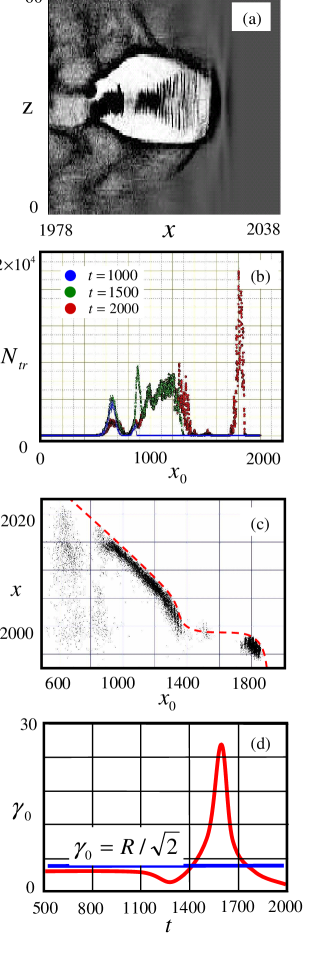
We carry out a numerical simulation of laser-plasma interaction by PIC VLPL3D code. The laser pulse is circularly polarized and has the envelope , where is the pulse duration, is the focused spot size and is the normalized vector potential, which corresponds to the laser intensity , is the laser wavelength. The plasma density is so that the parameters are close to that used in experiments Faure2004 . The typical distribution of the electron density in the bubble regime is shown in Fig. 2(a) when laser pulse has passed the distance in plasma. Because of the large number of trapped electrons the field enhancement effect is suppressed and the bubble shape deviates from the ideal spherical one. We modify the code to track individual particles over the full simulation. To separate trapped electrons, we introduce an energy threshold: we assume that an electron was trapped if its maximum energy exceeds MeV.
The distribution of the number of the electrons trapped in the bubble as a function of their initial position is shown in Fig. 2(b) for three instants of time. Fig. 2(b) demonstrates that the capture process is non-uniform and the number of trapped electrons changes along the laser path. The trapped electrons start motion from position at that corresponds to the electron coordinates , and the bubble center position according to our model. If the bubble propagates with velocity then . For the particle position we have , where is longitudinal component of the electron velocity and . Differentiating this equation with respect to we get , where we use . In our model is a function of and for a highly relativistic electron , we can write a . This derivation does not take into account the bubble shape deformation. However, it follows from our simulations that calculated from largely determines the gamma-factor of the bubble back because the trapped electrons with spent most of time in the bubble back. It is seen from Fig. 2(b)-(d) that the self-injection is strongly correlated with this factor. The number of trapped particles per laser period peaks in the regions and , where is minimal. Vice versa, for when the number of the trapped particles becomes negligible that agrees with predictions of the model.
In Conclusion we present the model for electron self-injection in the relativistic plasma wakefield generated by a short laser pulse or by an electron beam. The density threshold for electron self-injection is predicted by our model that is different from the self-injection condition proposed in Ref. Lu2007 . The evidences of such threshold have been observed in experiments Faure2006 . The model can also explain electron self-injection scheme based on downward plasma density transition Suk2001 . Such transition leads to the bubble elongation because of plasma density decreasing Further studies are neededand sharply reduces the gamma-factor of the bubble back thereby strongly enhancing self-injection. Recently, a strong impact of the wake phase velocity on electron trapping was also observed experimentally Fang2009 that is consistent with our model. However, the accurate measurements of the bubble velocity and the structure of the electromagnetic field in the bubble are needed for careful verification of the obtained results. Much effort is now mounted in theory and in experiments to control the emittance and the energy spread of the accelerated electron bunch. It follows from the obtained result that the self-injection strongly depends on the wake phase velocity that can be controlled, for example, by plasma density profiling Pukhov2008 . Therefore, the obtained results can be used to optimize the plasma-based acceleration.
Acknowledgements.
This work has been supported in parts by Russian Foundation for Basic Research (Grant No 07-02-01239, 07-02-01265, 08-02-01209) and by DFG Transregio TR-18, Germany.References
- (1) S.P.D. Mangles et al., Nature (London) 431, 535 (2004).
- (2) C.G.R. Geddes et al., Nature (London) 431, 538 (2004).
- (3) J. Faure et al., Nature (London) 431, 541 (2004).
- (4) W.P. Leemans et al., Nature Physics 2, 696 (2006).
- (5) I. Blumenfeld et al., Nature 445, 741 (2007).
- (6) A. Pukhov and J. Meyer-ter-Vehn, Appl. Phys. B 74, 355 (2002).
- (7) J.B. Rosenzweig et al., Phys. Rev. A 44, R6189 (1991).
- (8) E. Esarey and M. Pilloff, Phys. Plasmas 2, 1432 (1995).
- (9) C.B. Schroeder et al., Phys. Plasmas 13, 033103 (2006).
- (10) E. Esarey et al., Phys. Rev. Lett. 79, 2682 (1997).
- (11) J. Faure et al., Nature 444, 737 (2006).
- (12) S. Bulanov et al., Phys. Rev. E 58, R5257 (1998).
- (13) T. Esirkepov et al., Phys. Rev. Lett. 96, 014803 (2006).
- (14) H. Suk et al., Phys. Rev. Lett. 86, 1011 (2001).
- (15) W. Lu et al., Phys. Plasmas 13, 056709 (2006).
- (16) M. Tzoufras, et al., Phys. Rev. Lett. 101, 145002 (2008).
- (17) W. Lu et al., Phys. Rev. Lett. 96, 165002 (2006).
- (18) A. Zhidkov et al., Phys. Rev. E 69, 035401(R) (2004).
- (19) W. Lu et al., Phys. Rev. STAB 10, 061301 (2007).
- (20) I. Kostyukov, A. Pukhov and S. Kiselev, Phys. Plasmas 11, 5256 (2004).
- (21) S.V. Bulanov et al., Phys. Rev. Lett. 78, 4205 (1997).
- (22) F. Fang et al., Plasma Phys. Control. Fusion 51, 024003 (2009).
- (23) A. Pukhov and I. Kostyukov, Phys. Rev. E 77, 025401(R) (2008).