“Light Sail” Acceleration Revisited
Abstract
The dynamics of the acceleration of ultrathin foil targets by the radiation pressure of superintense, circularly polarized laser pulses is investigated by analytical modeling and particle-in-cell simulations. By addressing self-induced transparency and charge separation effects, it is shown that for “optimal” values of the foil thickness only a thin layer at the rear side is accelerated by radiation pressure. The simple “Light Sail” model gives a good estimate of the energy per nucleon, but overstimates the conversion efficiency of laser energy into monoenergetic ions.
Radiation Pressure Acceleration (RPA) of ultrathin solid targets by superintense laser pulses has been proposed as a promising way to accelerate large numbers of ions up to “relativistic” energies, i.e. in the GeV/nucleon range Esirkepov et al. (2004); Zhang et al. (2007a); Robinson et al. (2008); Klimo et al. (2008); Yan et al. (2008); Qiao et al. (2009); Gonoskov et al. (2009); Tripathi et al. (2009); Rykovanov et al. (2008). The simplest model of this acceleration regime is that of a “perfect” (i.e. totally reflecting) plane mirror boosted by a light wave at perpendicular incidence Simmons and McInnes (1993), which is also known as the “Light Sail” (LS) model. The LS model predicts the efficiency , defined as the ratio between the mechanical energy of the mirror over the electromagnetic energy of the light wave pulse, to be given by
| (1) |
where is the mirror velocity; hence, RPA becomes more and more efficient () as . Heuristically, Eq.(1) can be explained by the conservation of the number of “photons” of the light wave reflected by the moving mirror in a small time interval: each photon has energy , thus the total energy of the incident and reflected pulses are given by and , where due to the Doppler effect, and the energy transfered to the mirror is given by their difference .
The predictions of the LS model are very appealing for applications, but one may wonder to what extent this picture is appropriate to describe the acceleration of a solid target by a superintense laser pulse. In the present paper, we revisit the LS model with the help of simple modeling and particle-in-cell (PIC) simulations. We address issues outside the model itself, such as the effects of nonlinear reflectivity and charge depletion, and on this basis we explain a few features observed in simulations. Our main result is that the LS model is accurate in predicting the ion energy but overstimates the corresponding conversion efficiency, i.e. the fraction of the laser pulse energy transferred into quasi-monoenergetic ions, due to the fact that only a layer of the foil at its rear side is accelerated by RPA.
Our analysis is confined to a one-dimensional (1D) approach for the sake of simplicity and because multi-dimensional simulations showed that a “quasi-1D” geometry has to be preserved in the acceleration stage (by using flat-top intensity profiles) to avoid early pulse transmission due to the expansion of the foil in the radial direction Liseykina et al. (2008). Circularly polarized pulses are used to reduce electron heating Macchi et al. (2005), an approach followed by several groups for efficient acceleration of thin foils Zhang et al. (2007a); Robinson et al. (2008); Klimo et al. (2008); Yan et al. (2008); Qiao et al. (2009); Liseykina et al. (2008). We do not consider intensities high enough that ions become relativistic within the first laser cycle; this condition may affect the early stage of charge depletion (e.g. by narrowing the temporal scale separation between ions and electrons), and lead to different estimates Esirkepov et al. (2004); Qiao et al. (2009).
The LS model is based on the following equation of motion for the foil
| (2) |
where , , is the light wave intensity, and are the mass density and thickness of the foil, is the reflectivity in the rest frame of the foil, and . For suitable expressions of , the final velocity can be obtained from Eq.(2) as a function of the pulse fluence . For , one obtains
| (3) |
In the last equality we wrote the fluence in dimensionless units as , where is the dimensionless pulse amplitude and is the pulse duration in units of the laser period, and introduced the parameter which characterizes the optical properties of a sub–wavelength plasma foil Vshivkov et al. (1998). In these equations, is the initial electron density, is the cut-off density, and is the laser wavelength. In practical units, and for a circularly polarized laser pulse. Using Eq.(3) it is found that with a , laser pulse and a target of density, per nucleon may be obtained. As the LS model assumes the target to be a perfect mirror (i.e. rigid and totally reflecting), it implies that all the ions are accelerated to the same velocity and the spectrum is perfectly monoenergetic.
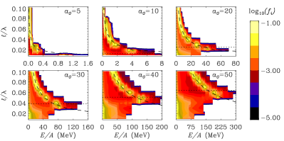
Fig.1 shows a parametric study of the ion spectrum vs. and from PIC simulations. For all runs, , and the pulse has a flat–top envelope with 1 cycle rise and fall times and 8 cycles plateau. For each value of and for less than a threshold value we observe a narrow spectral peak, whose energy increases with decreasing and is in very good agreement with the predictions of the LS model, assuming . A typical lineout of the spectrum is shown in Fig.2 a). For , the peak disappears and a thermal–like spectrum is observed. This is correlated with an almost complete expulsion of the electrons from the foil in the forward direction at the beginning of the interaction, leading to a Coulomb explosion of the ions.
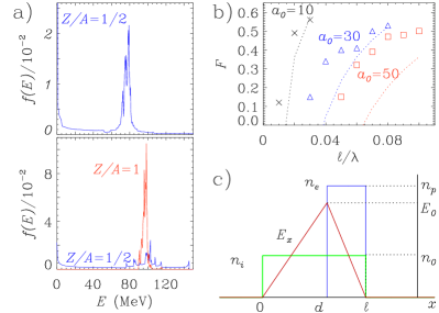
The results of Fig.1 show that the LS model is useful for quantitative predictions of the ion energy, but also suggest several questions of interest both for the basic physics of RPA and its applications. How is determined? Does the reflectivity of the foil and relativistic effects on the latter play a role? As the radiation pressure tends to separate electrons from ions, does the foil remain neutral before and/or after the acceleration stage? Moreover, as shown shown in Fig.2 b), the “monoenergetic” peak contains just a fraction of the total number of ions, and such fraction depends on and . This is different from the assumption of the LS model, which assumes all the ions in the foil to move coherently with the foil, and may sound surprising, since the peak energy is in agreement with the LS formula where the whole mass of the foil, including low-energy ions out of spectral peak, is used. In the following we provide answers to the questions above by discussing effects not included in the simplest LS model, i.e. beyond the description of the foil as a perfect, rigid mirror.
First we discuss effects related to the reflectivity of the plasma foil. For very high intensities, electrons oscillate with relativistic momenta in the laser field, leading to a nonlinear dependence of upon . An explicit expression can be found analytically by using the model of a delta–like “thin foil” Vshivkov et al. (1998), i.e. a plasma slab located at with electron density . The expression obtained for in the rest frame of the foil is very well approximated by
| (4) |
A threshold for self-induced transparency of the foil may thus be defined as when , i.e. in most cases of interest. According to Eq.(4), the total radiation pressure on the target
| (5) |
becomes independent upon for . Thus, the maximum radiation pressure is obtained for , and in this condition typically for solid densities. This suggests that the optimal thickness is determined by the condition , in good agreement with the simulation results in Fig.1 and as also found by other studies Tripathi et al. (2009); Esirkepov et al. (2006).
The nonlinear reflectivity of the thin foil is determined by the transverse motion of electrons (in the foil plane). However, for a thin but “real” target the radiation pressure tends to push electrons also in longitudinal direction, and may remove them from the foil. Let us compare with the electrostatic pressure that would be generated if all electrons would be removed from the foil. The condition
| (6) |
corresponds to the threshold for the removal of all electrons from the foil. However, when Eq.(4) is used for , Eq.(6) reduces to , while for we find that holds. It is thus possible to produce a density distribution where all electrons pile at the rear surface of the foil. In fact, if and , the laser pulse compresses the electron layer while keeping constant since the product does not change during the compression; at the same time almost no electrons are ejected from the rear side because the ponderomotive force vanishes there if , and so does the electrostatic field: the qualitative profiles of the electron density and of the electric field are shown in Fig.2 c). Since for close to the equilibrium between the electrostatic and radiation pressures occurs only when the depth of the region of charge depletion is close to , electrons are compressed in a very thin layer. The depletion depth may be estimated from the equilibrium condition
| (7) |
when , which yields . It is worth to point out that these considerations are appropriate for a circularly polarized laser pulse; for linear polarization, all electrons may be expelled for a transient stage under the action of the force whose peak value per unit surface exceeds due to its oscillating component. Complete expulsion of electrons for has been discussed in Ref.Bulanov et al. (2008).
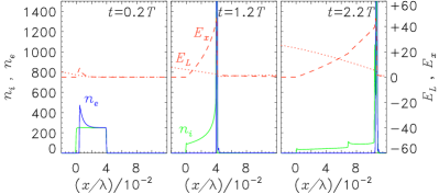
The snaphshots from a PIC simulation shown in Fig.3 for a case with and confirm the scenario outlined above. The electron density reaches values (out of scale in Fig.3) up to tens of the initial density. A very high resolution is used to resolve the density spike properly. For a laser pulse with flat–top envelope the density spiking at the rear side of the foil is particularly evident, but we verified that it occurs also for a “” envelope. Similar features were observed also in Refs.Yan et al. (2008); Tripathi et al. (2009), but not discussed in detail.
The electron compression in a thin layer during the initial “hole boring” stage has important consequences for the later acceleration stage. Let us refer to the approximate field profiles in the initial stage, sketched in Fig.2 c), which were the basis of the model presented in Ref.Macchi et al. (2005). This model suggests that only the ions located initially in the electron compression layer () will be bunched and undergo RPA (via a “cyclic” acceleration as discussed in Refs.Zhang et al. (2007a); Robinson et al. (2008); Klimo et al. (2008)) because for these ions only the electrostatic pressure balances the radiation pressure, while the ions in the electron depletion layer () will be accelerated via Coulomb explosion, i.e. by their own space-charge field. This is exactly what is observed in the PIC simulations, both in the density profiles (see Fig.3 at ) and in the ion spectra. This effect also explains how RPA with circularly polarized pulses may work also in double layer targets Esirkepov et al. (2006), if the thickness of a thin layer on the rear side matches . Fig.2 shows ion spectra for the same simulation of Fig.3 and for a simulation with the same parameters, but where ions in a surface layer of thickness have been replaced by protons. A fraction of heavier ions is also accelerated to the same energy per nucleon as the protons, a typical feature of RPA of a thin plasma foil.
As an additional consequence of the piling up of electrons at the rear surface, the portion of the foil which is boosted by the laser pulse is negatively charged due to the excess of electrons. However, the simulations show that when the laser pulse is over the excess electrons detach from the foil and move in the backward direction, so that the accelerated layer is eventually neutral. This is important to avoid a later Coulomb explosion of the layer and to preserve a monoenergetic spectrum. During the acceleration, the longitudinal field at the surface of the accelerated layer is almost constant implying that the charge there contained is also constant. It is thus possible to estimate the fraction of accelerated ions from the initial equilibrium condition, Eq.(7), as
| (8) |
The agreement with data in Fig.2 b) is qualitative, with large deviations as becomes significantly smaller than one. As explained below, a lower bound on is determined by energy conservation.
A simple argument of force balance also explains why the energy of the spectral peak in Fig.2 is in very good agreement with the predictions of the LS model where the initial value of the foil thickness is used, while only a layer of thickness is accelerated via RPA. Let us refer again to the profiles of Fig.2. The equilibrium condition for electrons implies
| (9) |
The electric field pushes ions in the compression layer , exerting a total pressure
| (10) |
where we used Eq.(9) and assumed . The equation of motion for the ion layer, in the early stage, can be thus written as
| (11) |
which is trivially equivalent to
| (12) |
i.e. to the equation of motion one would write for the whole foil. The argument may be applied also when the layer is in motion leading to the same conclusion. Having the same as the whole foil implies that the energy per nucleon and the efficiency (1) will be also the same, but the total kinetic energy will be lower for the thin layer. The rest of the absorbed energy is stored in the electrostatic field and as kinetic energy of the ions in the region. Let us consider for example the energy stored in the electrostatic field. At the time , the field between the initial and the actual positions of the front surface of the foil is given approximately by , where , corresponding to an electrostatic energy per unit surface
| (13) |
which varies in time as
| (14) |
Dividing (14) by the laser intensity we obtain the “conversion efficiency” into electrostatic energy
| (15) |
If and thus , we would obtain that is unphysical. Thus, the energy stored in the electrostatic field also prevents the accelerated layer thickness to shrink to zero.
In conclusion, we have revisited the “Light Sail” model of Radiation Pressure Acceleration of a thin plasma foil. The nonlinear reflectivity of the foil determines the “optimal” condition , for which the energy in the RPA spectral peak is highest and in good agreement with the LS model formula where the total thickness (or the total mass) of the foil enters as a parameter. However, not all the foil is accelerated, but only a thin layer at the rear side of thickness ; the apparent paradox is solved by observing that, to keep electrons in a mechanical quasi-equilibrium, the electrostatic pressure pushing ions in the accelerated layer is times the radiation pressure on electrons, so that the equation of motion for the thin layer is the same as if the whole foil were accelerated. Finally, we showed that the energy stored in the electrostatic field is comparable to the kinetic energy and must be taken into account. For applications, the most relevant consequences and differences with respect to the simplest LS picture are that the number of “monoenergetic” ions is reduced, so that the actual efficiency may be quite lower than given by Eq.(1), and that also light ions in a thin layer at the rear surface (e.g., hydrogen impurities) may be accelerated by RPA.
Support from CNR via a RSTL project and use of supercomputing facilities at CINECA (Bologna, Italy) sponsored by the CNR/INFM supercomputing initiative are acknowledged.
References
- Esirkepov et al. (2004) T. Esirkepov et al., Phys. Rev. Lett. 92, 175003 (2004).
- Zhang et al. (2007a) X. Zhang et al., Phys. Plasmas 14, 073101 (2007a).
- Robinson et al. (2008) A. P. L. Robinson et al., New J. Phys. 10, 013021 (2008).
- Klimo et al. (2008) O. Klimo, J. Psikal, J. Limpouch, and V. T. Tikhonchuk, Phys. Rev. ST Accel. Beams 11, 031301 (2008).
- Yan et al. (2008) X. Q. Yan et al., Phys. Rev. Lett. 100, 135003 (2008).
- Qiao et al. (2009) B. Qiao, M. Zepf, M. Borghesi, and M. Geissler, Phys. Rev. Lett. 102, 145002 (2009).
- Gonoskov et al. (2009) A. A. Gonoskov et al., Phys. Rev. Lett. 102, 184801 (2009).
- Tripathi et al. (2009) V. K. Tripathi et al., Plasma Phys. Contr. Fusion 51, 024014 (2009).
- Rykovanov et al. (2008) S. G. Rykovanov et al., New J. Phys. 10, 113005 (2008).
- Simmons and McInnes (1993) J. F. L. Simmons and C. R. McInnes, Am. J. Phys. 61, 205 (1993).
- Liseykina et al. (2008) T. V. Liseykina, M. Borghesi, A. Macchi, and S. Tuveri, Plasma Phys. Contr. Fusion 50, 124033 (2008).
- Macchi et al. (2005) A. Macchi, F. Cattani, T. V. Liseykina, and F. Cornolti, Phys. Rev. Lett. 94, 165003 (2005).
- Vshivkov et al. (1998) V. A. Vshivkov, N. M. Naumova, F. Pegoraro, and S. V. Bulanov, Phys. Plasmas 5, 2727 (1998).
- Bulanov et al. (2008) S. S. Bulanov et al., Phys. Rev. E 78, 026412 (2008).
- Esirkepov et al. (2006) T. Esirkepov, M. Yamagiwa, and T. Tajima, Phys. Rev. Lett. 96, 105001 (2006).